Meshing & Deploying connections on Suspension model of a car
AIM:
To do geometrical clean up for the given component, mesh the component with the given quality criteria and deploy appropriate connections on the FE model.
OBJECTIVE:
The main objective of the project is to mesh & deploy connections on a real-time suspension model of a passenger car along with the wheel and tyre.
PROCESS:
- Perform geometry clean up and resolve geometry errors.
- Extract the mid-surface of the component.
- Assign Property ID for the mid-surface and set the Quality criteria for meshing.
- Shell-mesh the mid-surfaces.
- Define volume and solid-mesh the volumes.
- Resolve tetra collapse & other quality issues.
- Deploying appropriate connections.
SOFTWARE USED:
ANSA (Automatic Net generation for Structural Analysis) v19.0.1 64-bit
MODEL:
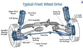
The suspension is a system of parts containing coil spring, shock absorber / damper, ball joint & other linkages. It is the system which connects the wheel & tyre with the chassis & body of the vehicle and allows relative motion between them.
The given CAD model is a suspension model of a passenger car with the wheel, tyre and the disc brake setup.
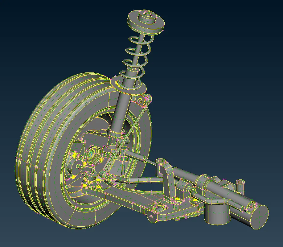
We have components with less thickness and others which have much larger thickness. We will be doing shell meshing (2D meshing) and solid meshing (3D meshing) according to the requirement.
GEOMETRY CHECKS:
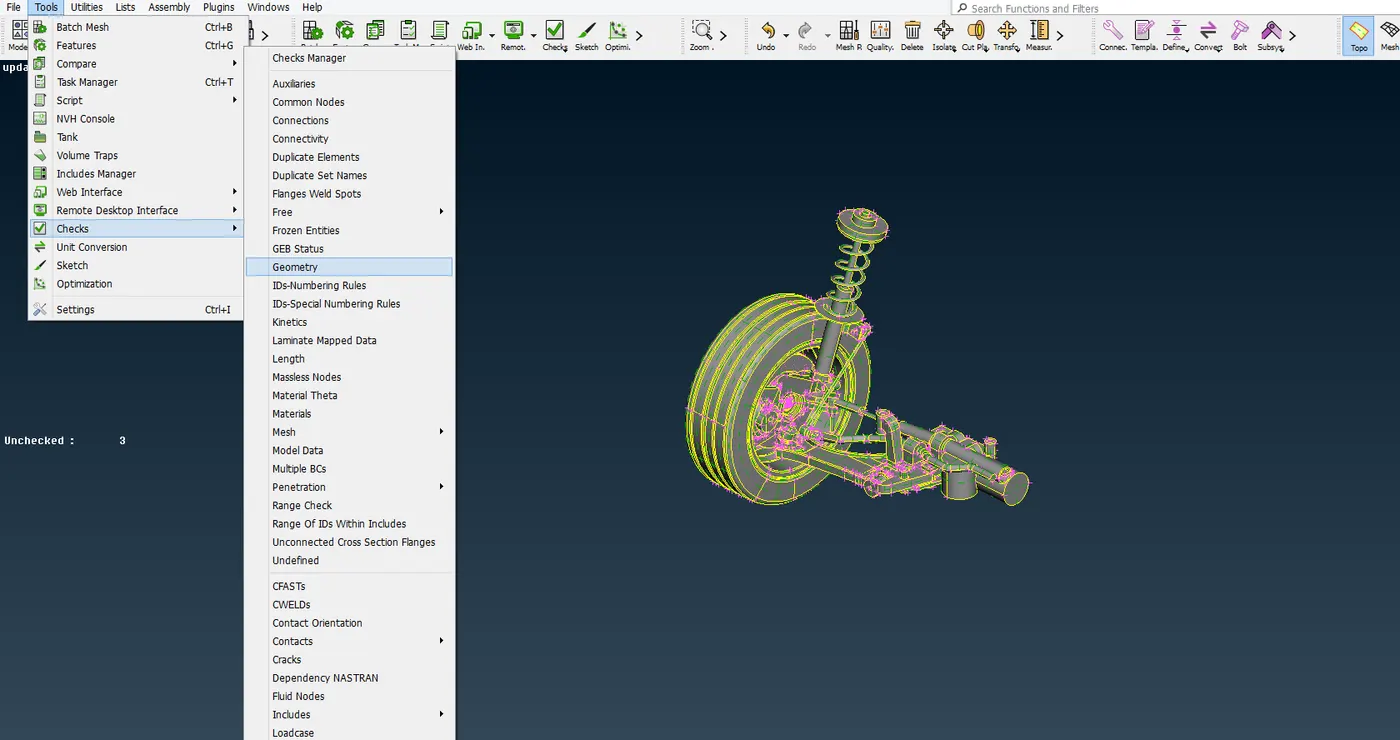
The geometry check is in the TOOLS tab under CHECKS -> GEOMETRY.
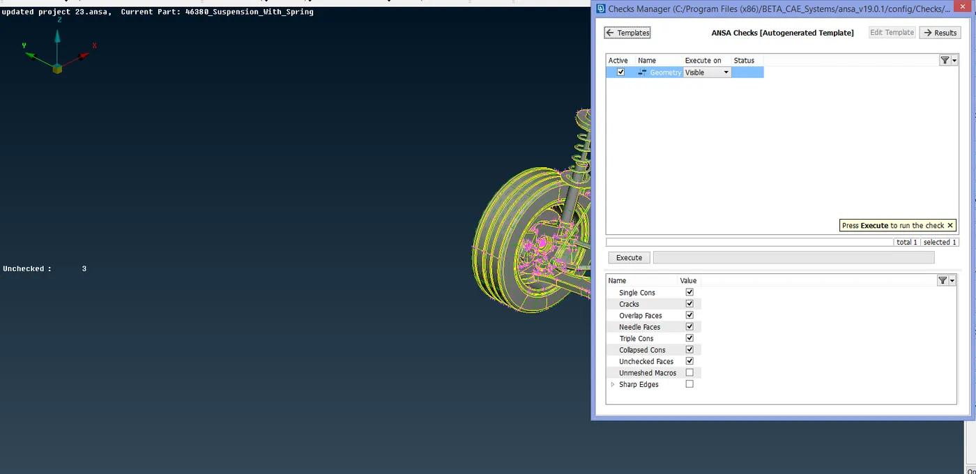
Upon executing, the errors in the model will pop up.
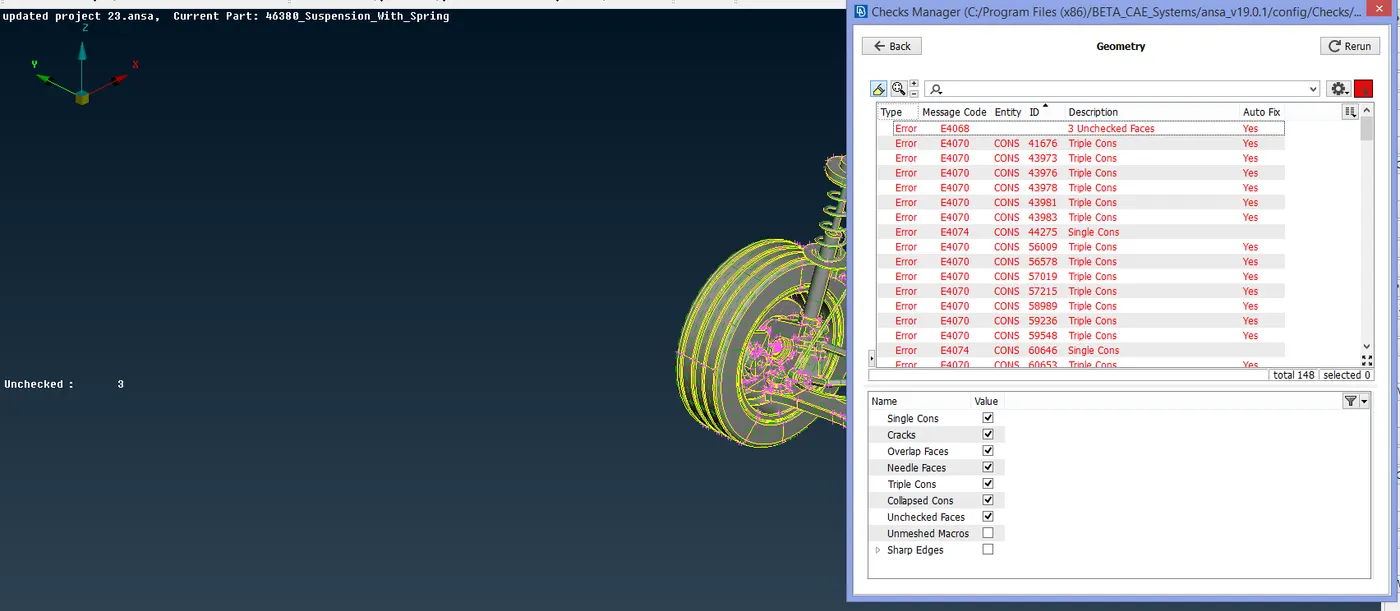
The errors can be fixed manually or can be fixed automatically by ANSA.
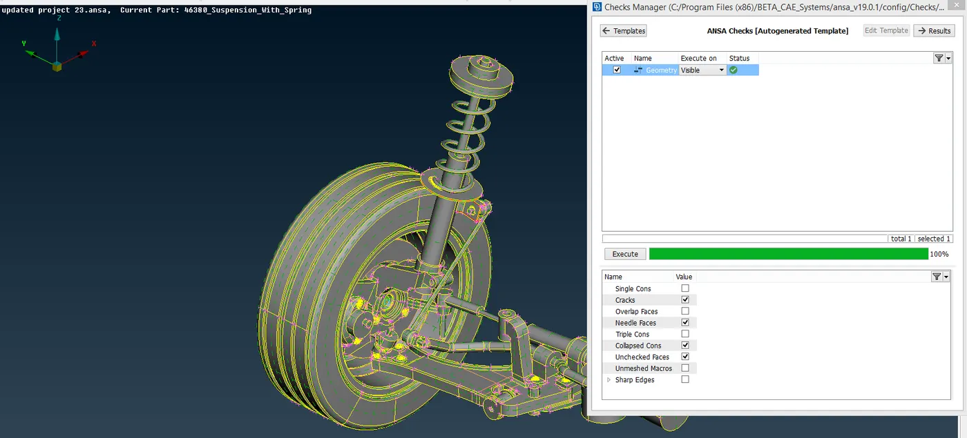
Once the errors are fixed, the geometry checks are run again to ensure no error is left un-resolved.
MIDSURFACE EXTRACTION:
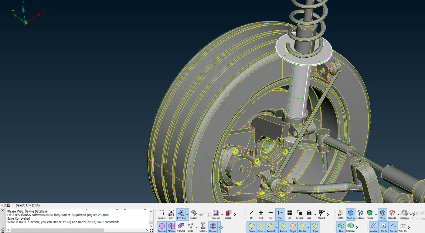
Before the mid-surface for the component is extracted, the thickness of the surfaces is to be measured. The components are separated using the iNOT command with PID Region selection.
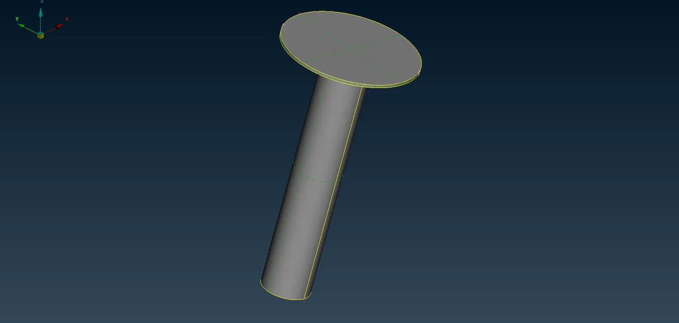
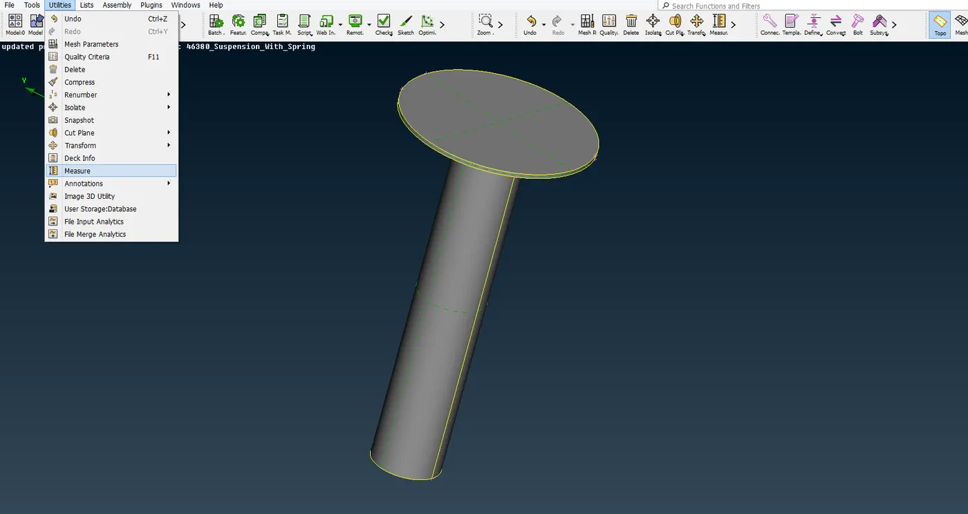
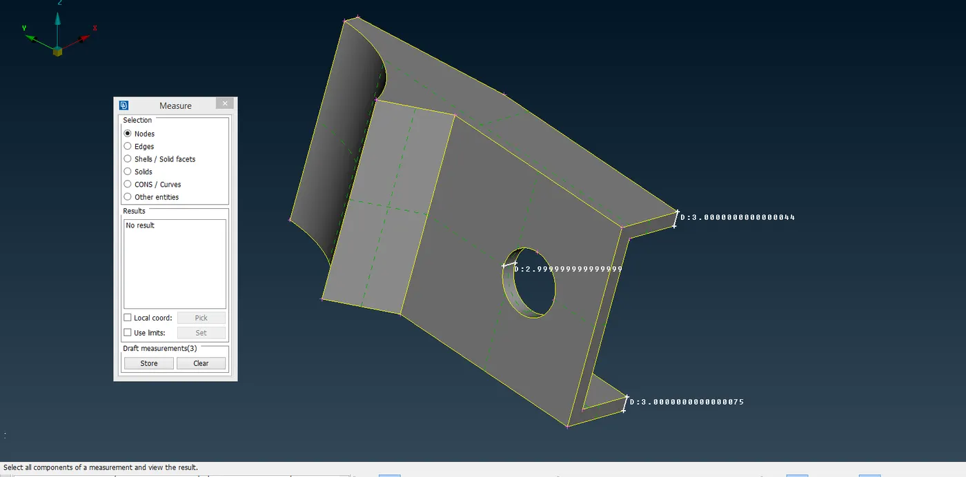
The thickness of the surfaces is measured using the MEASURE command in the UTILITIES tab.
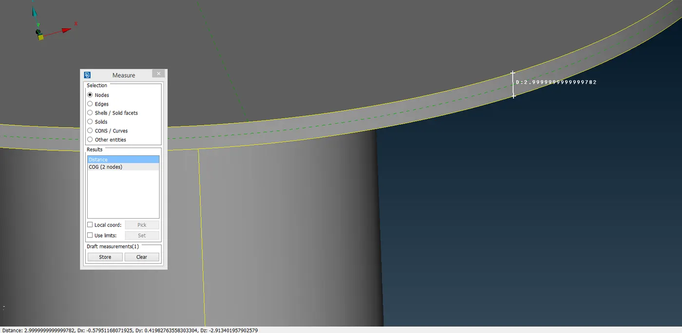
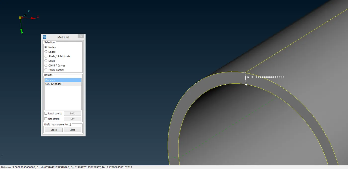
Once the thickness is measured, the surfaces are offset to half of the thickness value using the FACES -> OFFSET command in the TOPO module.
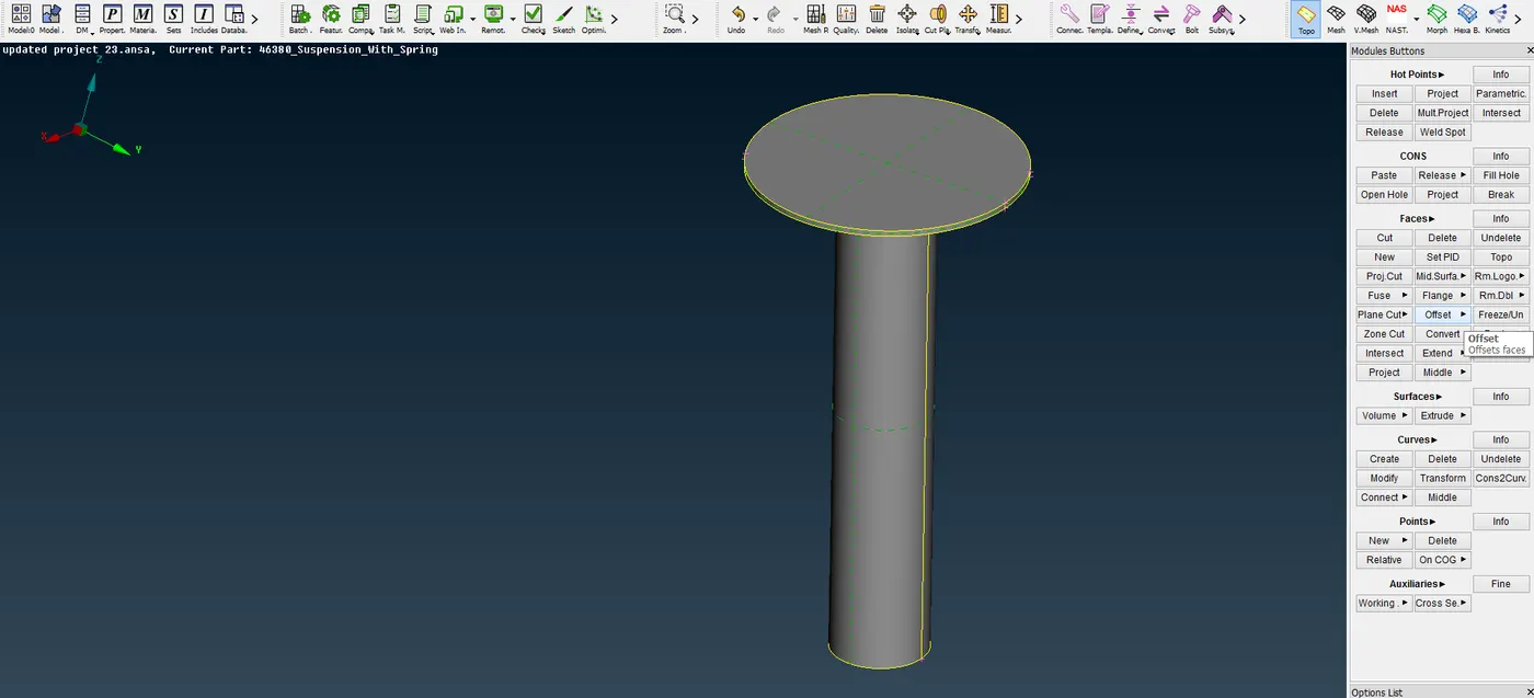
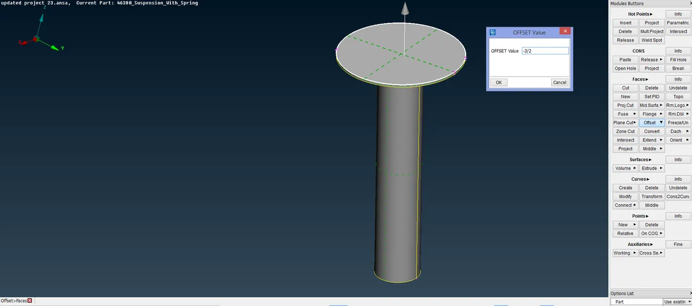
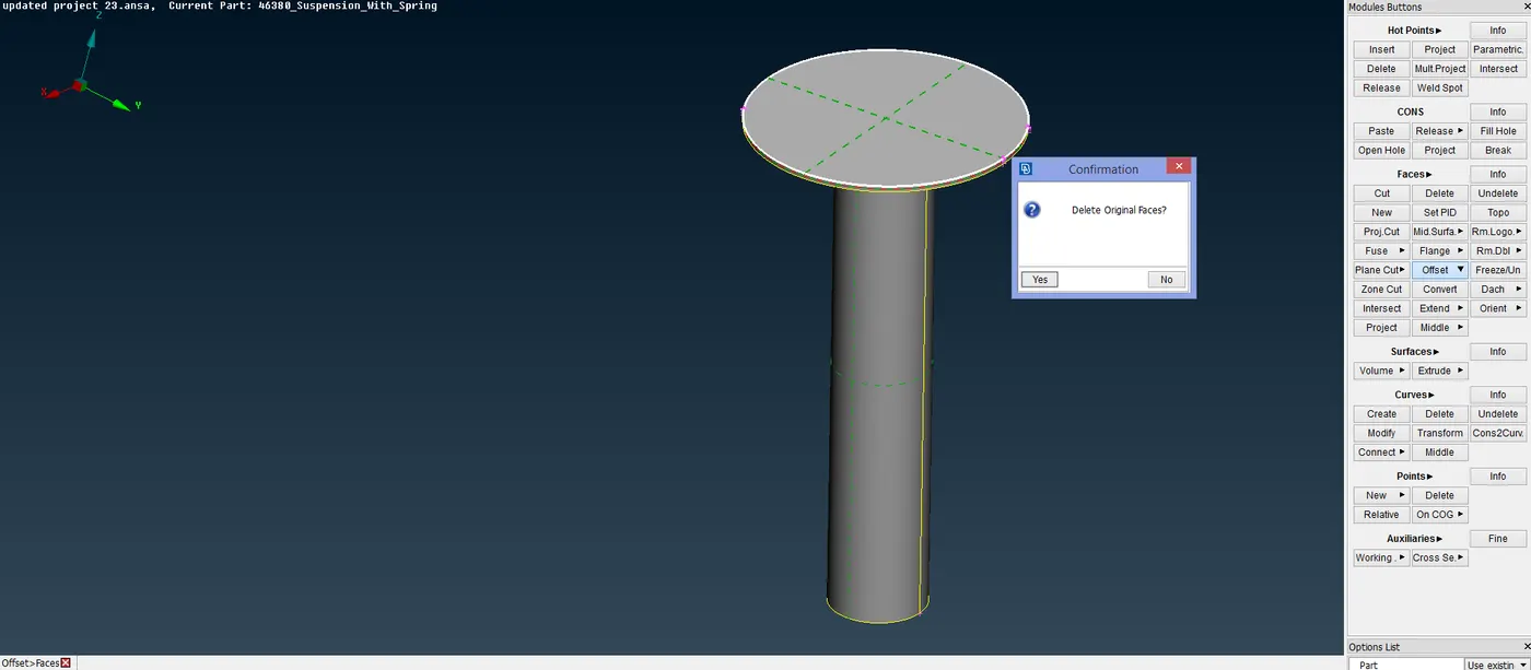
As the thickness is 3mm, the offset distance will be 1.5mm.
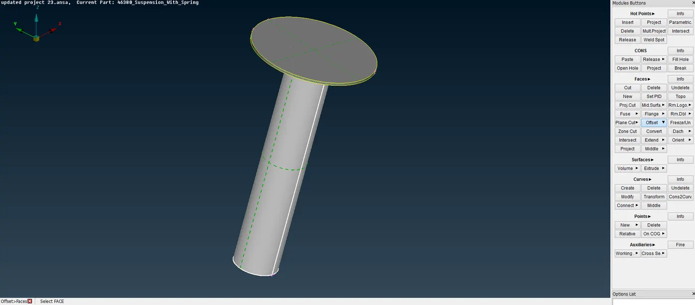
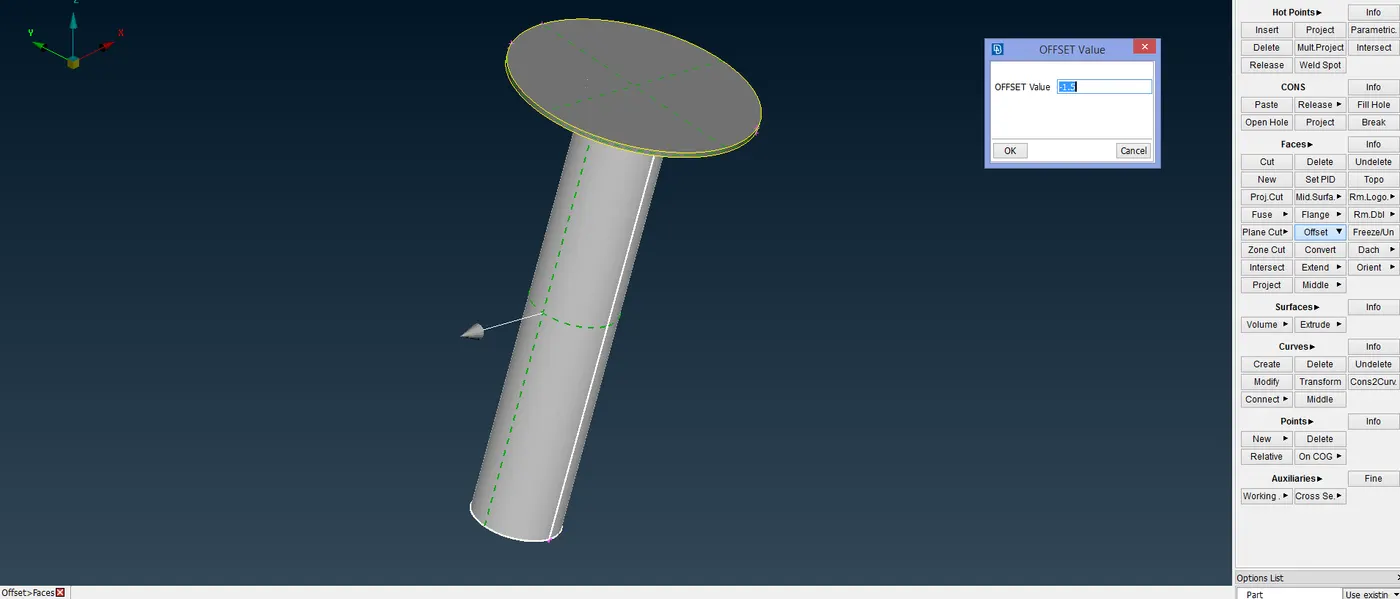
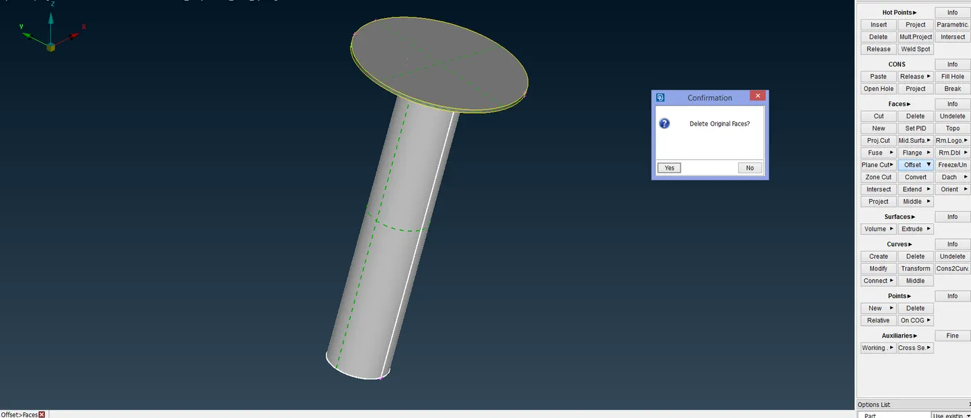
This way the mid-surface is generated for other surfaces also.
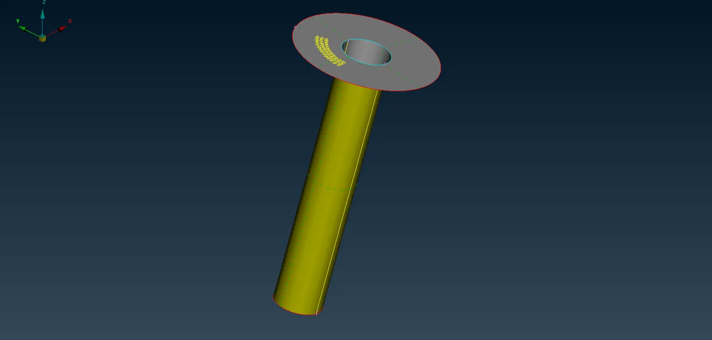
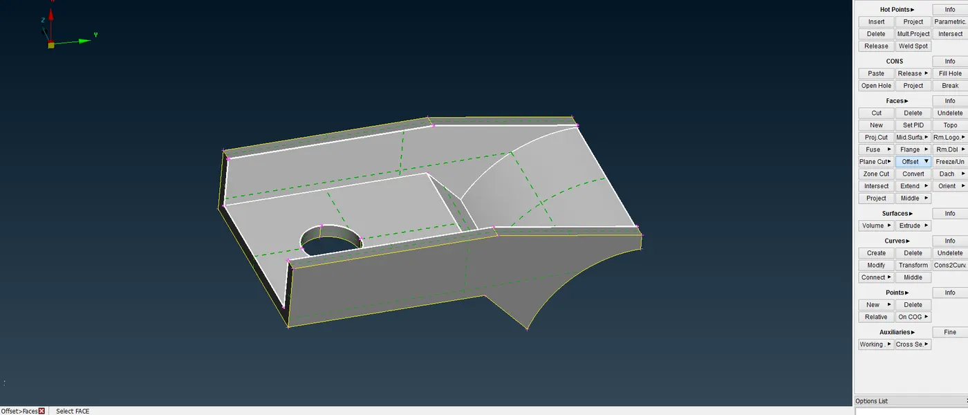
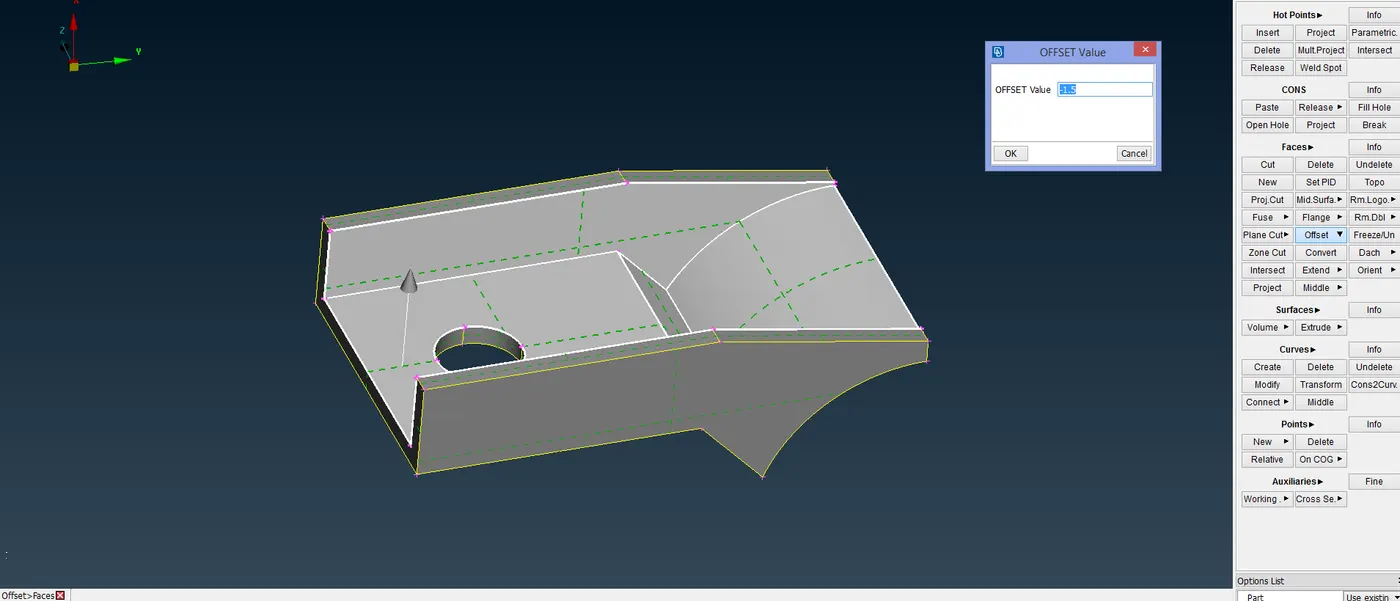
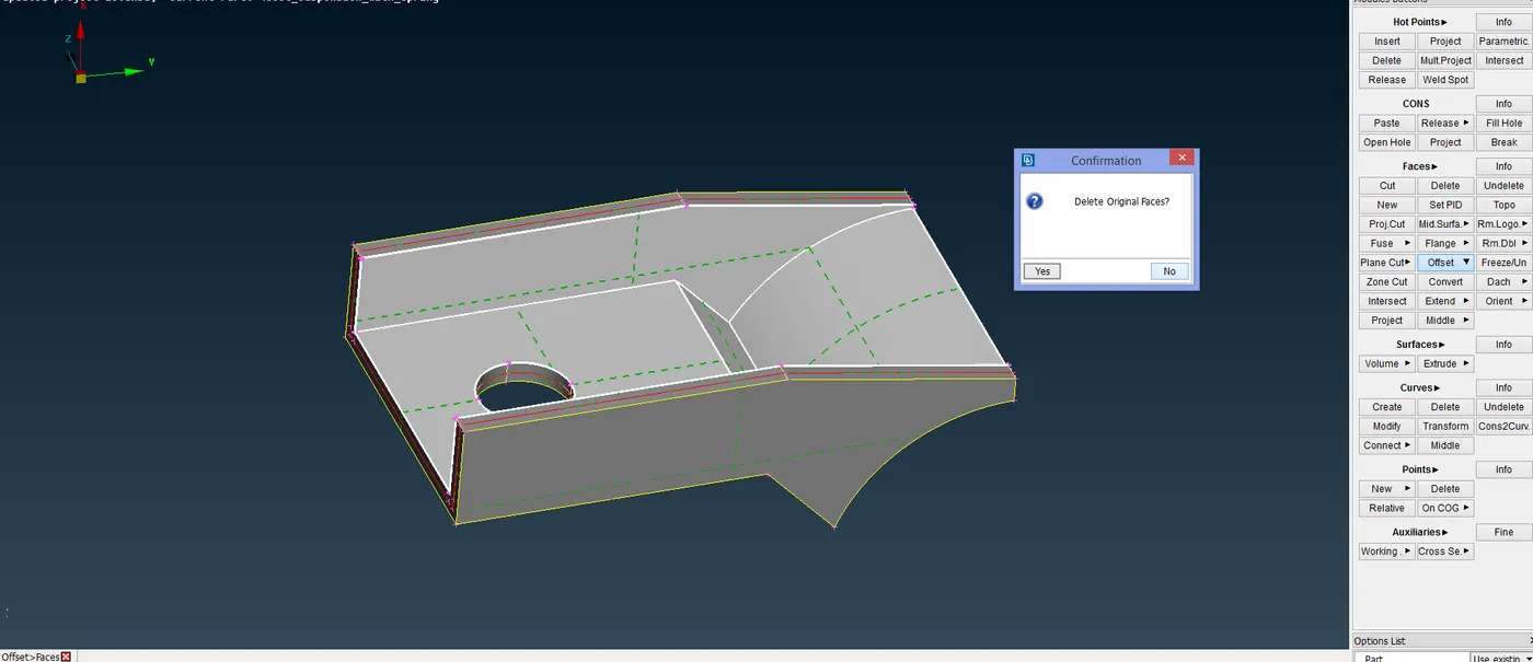
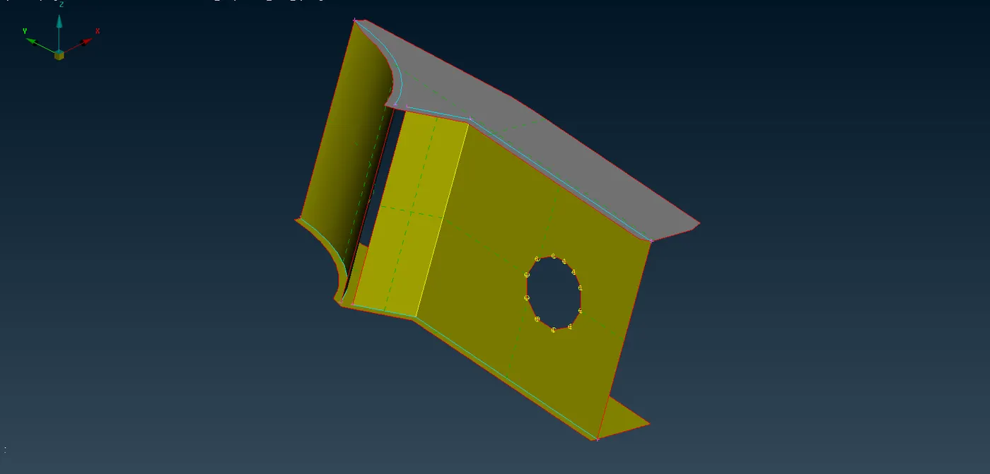
Once the mid-surfaces are extracted, some surfaces need to be extended and joint with other surfaces. This is done using the FACES -> EXTEND command.
ASSIGNING PROPERTY ID & QUALITY CRITERIA:
Property IDs are assigned to the mid-surfaces using the FACES -> SET PID command.
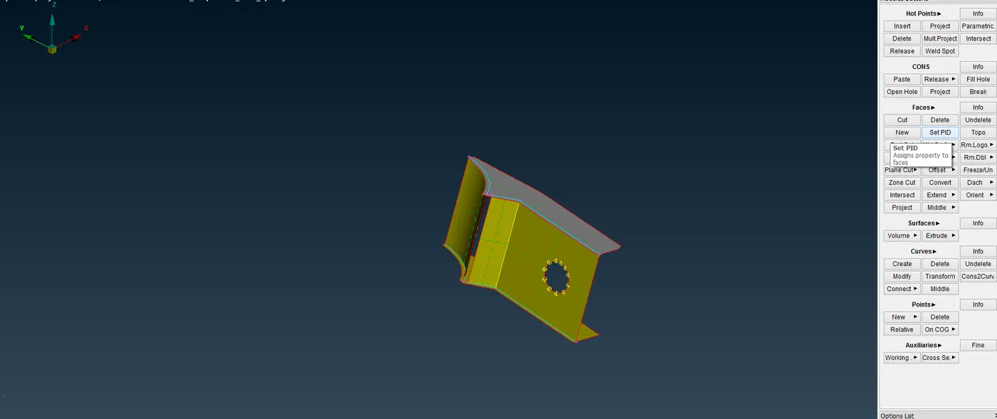
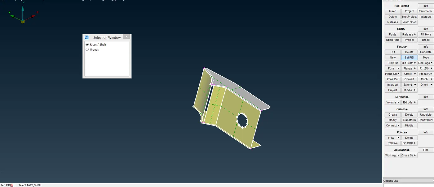
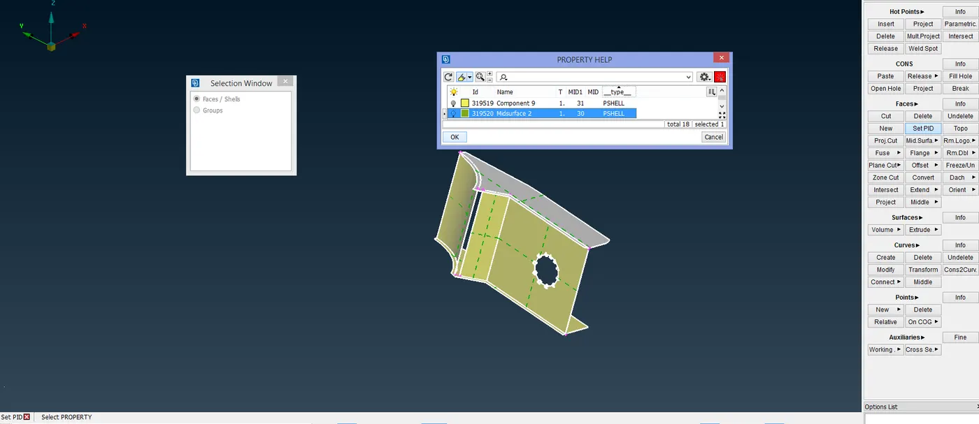
Once the command is selected, the mid-surface is selected with a box selection. Upon accepting the required Property ID is selected and the thickness value for that PID is set. In case PIDs are not available, a new PID can be created and assigned.
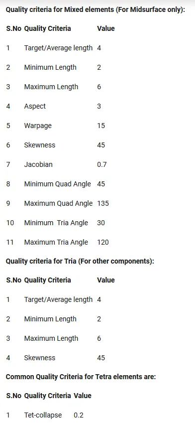
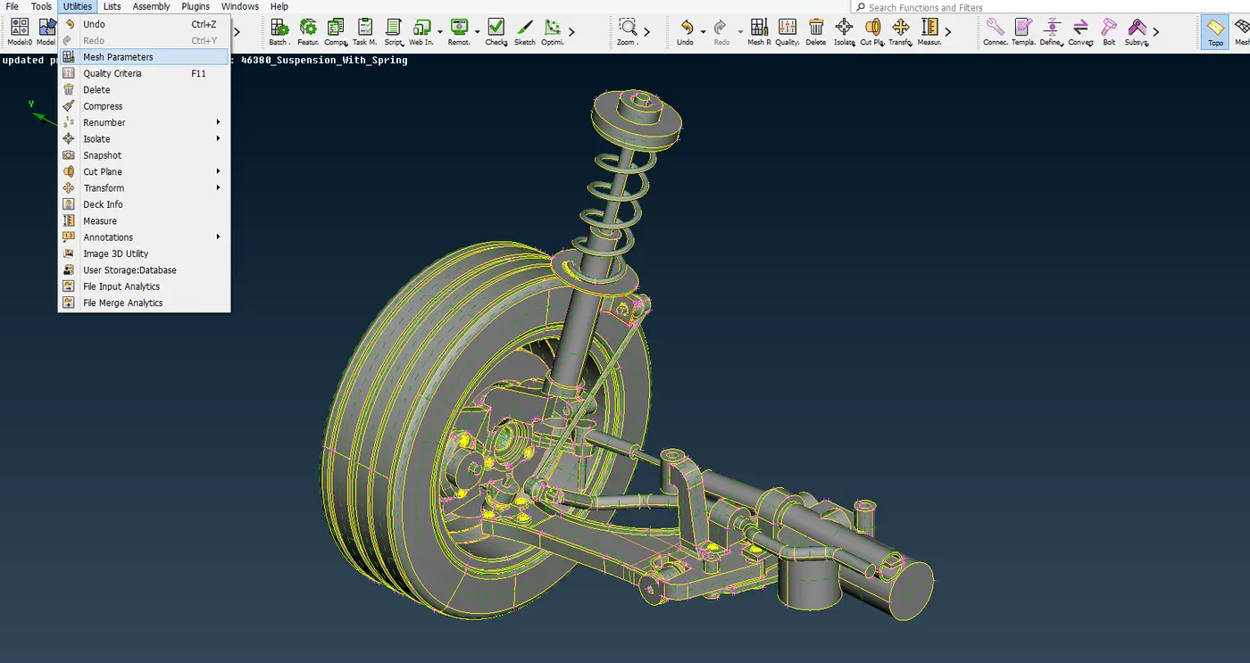
After the PID is set, the Mesh parameters are set. It is under the UTILITIES tab.
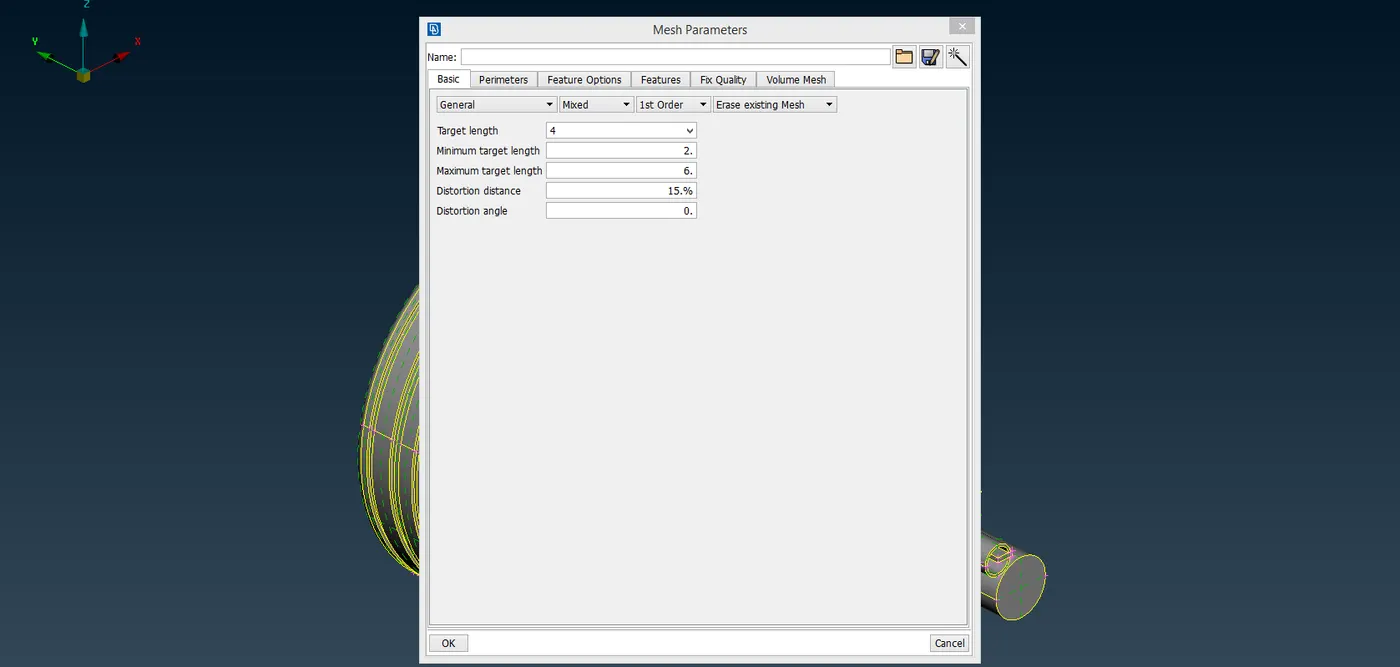
In the BASIC tab, the Minimum & Maximum element length and Target element length are given.
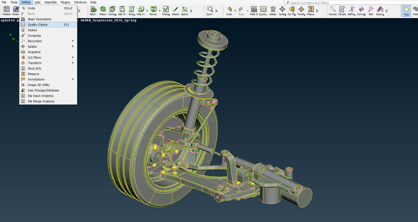
Then the Quality criteria are set. It is also under the UTILITIES tab. The F11 key is a shortcut to the Quality criteria, which can also be used.
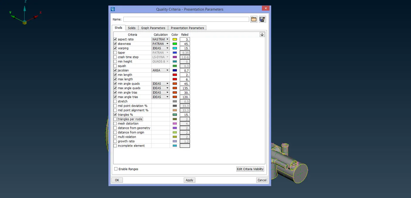
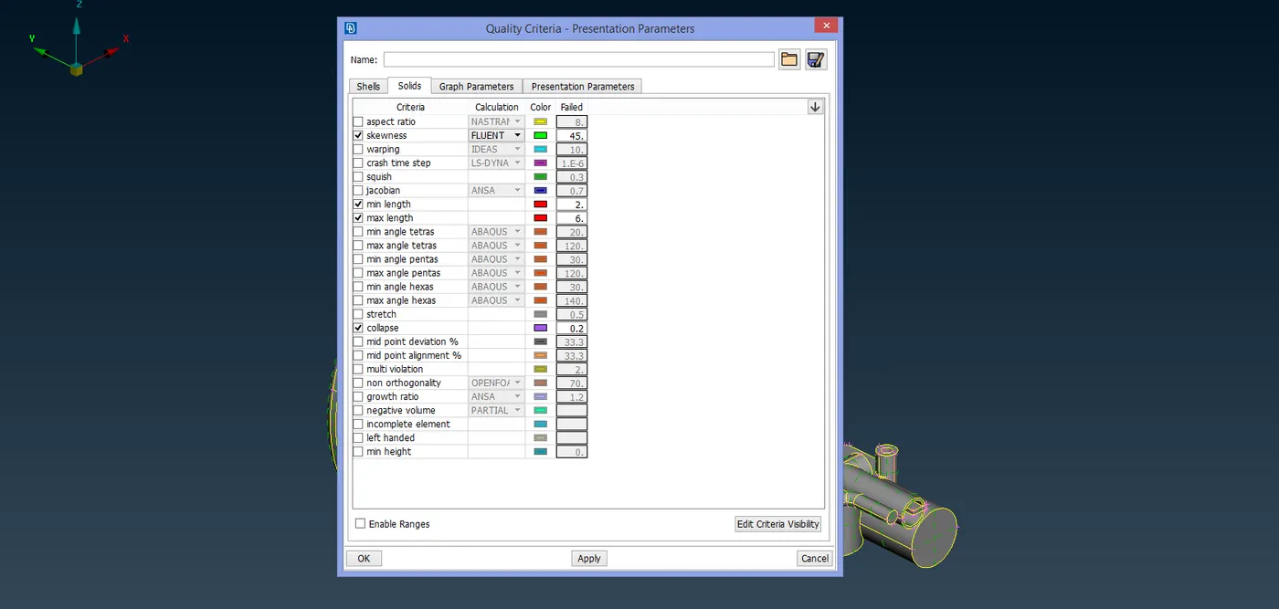
The Quality criteria values for Shell mesh are set in the Shells tab and for Solid mesh they are set in the Solids tab.
SHELL MESHING:
Meshing is done in the MESH module. Before the starting of meshing, the perimeter length is set to the Target element length using the PERIMETERS -> LENGTH command. The algorithms used for meshing are BEST meshing and SPOT meshing.
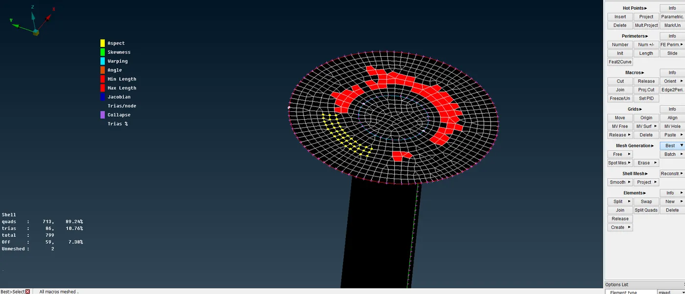
The command is selected and the surface to be meshed is selected. Upon executing the mesh is deployed on the surface.
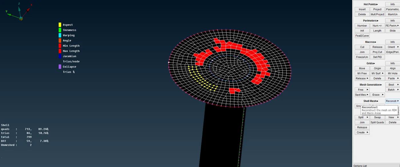
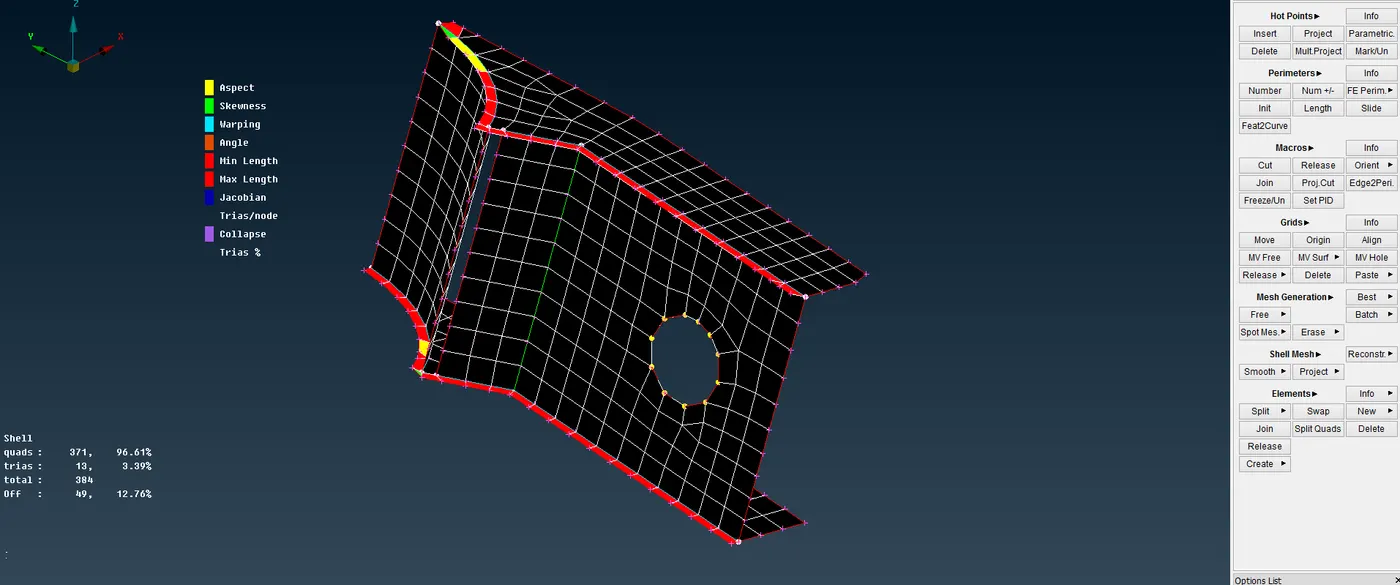
The SHELL MESH -> RECONSTRUCT command is used to re-construct the existing mesh to obtain a better mesh flow.
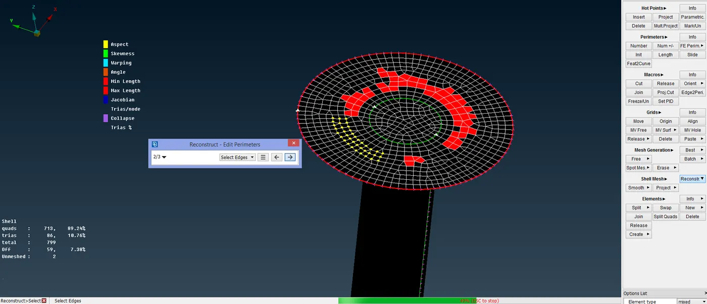
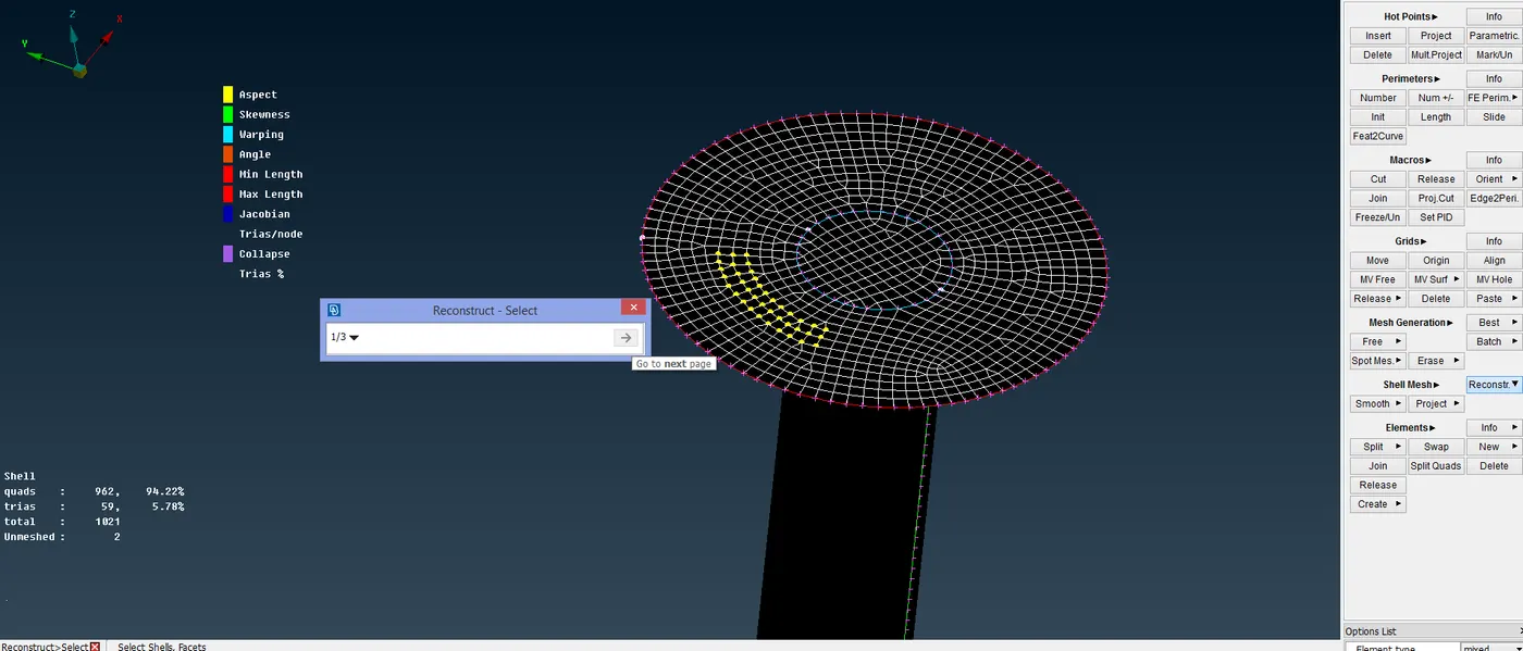
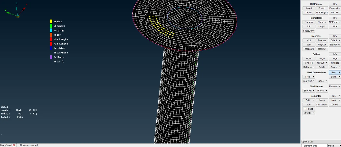
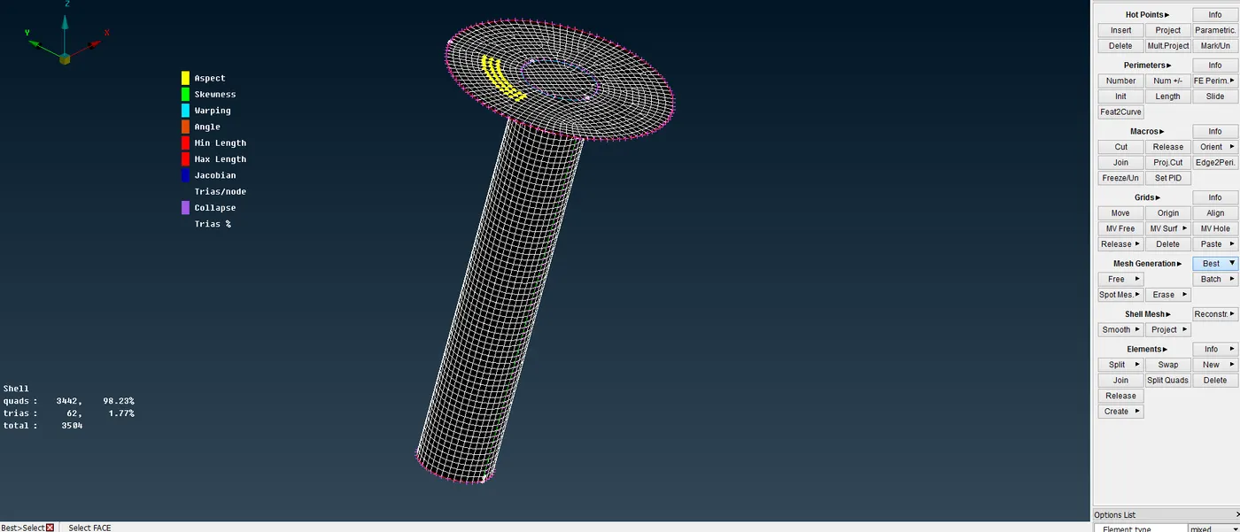
Similarly, the other mid-surface is also meshed.
DEFINING VOLUME & SOLID MESHING:
The components are selected using the iNOT command with feature selection as PID Region.
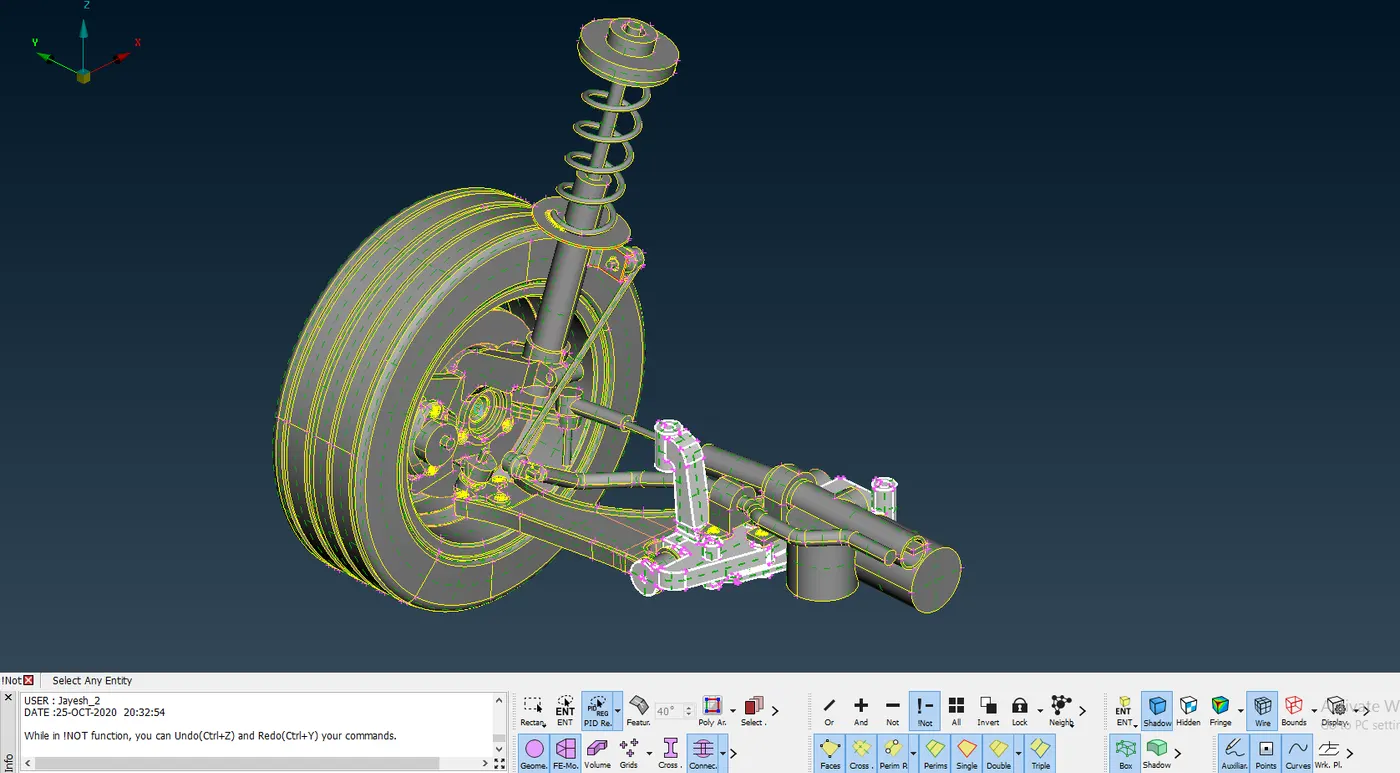
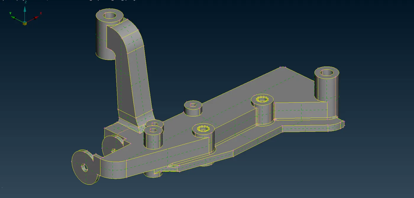
Defining of the volume and solid meshing is done in the Volume Mesh module. The VOLUMES -> DEFINE command is used to define the volume.
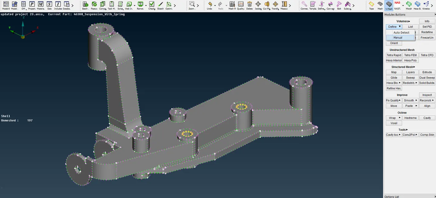
The component is box selected and the accepted. Then the volume is defined.
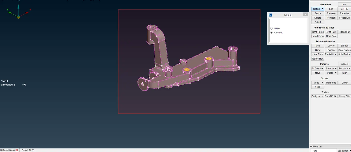
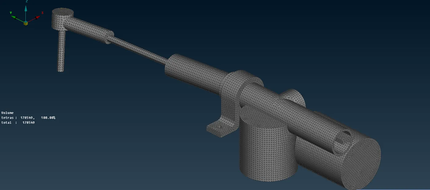
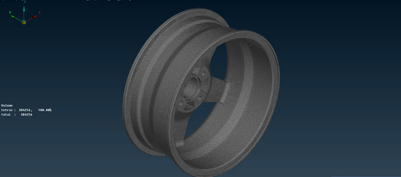
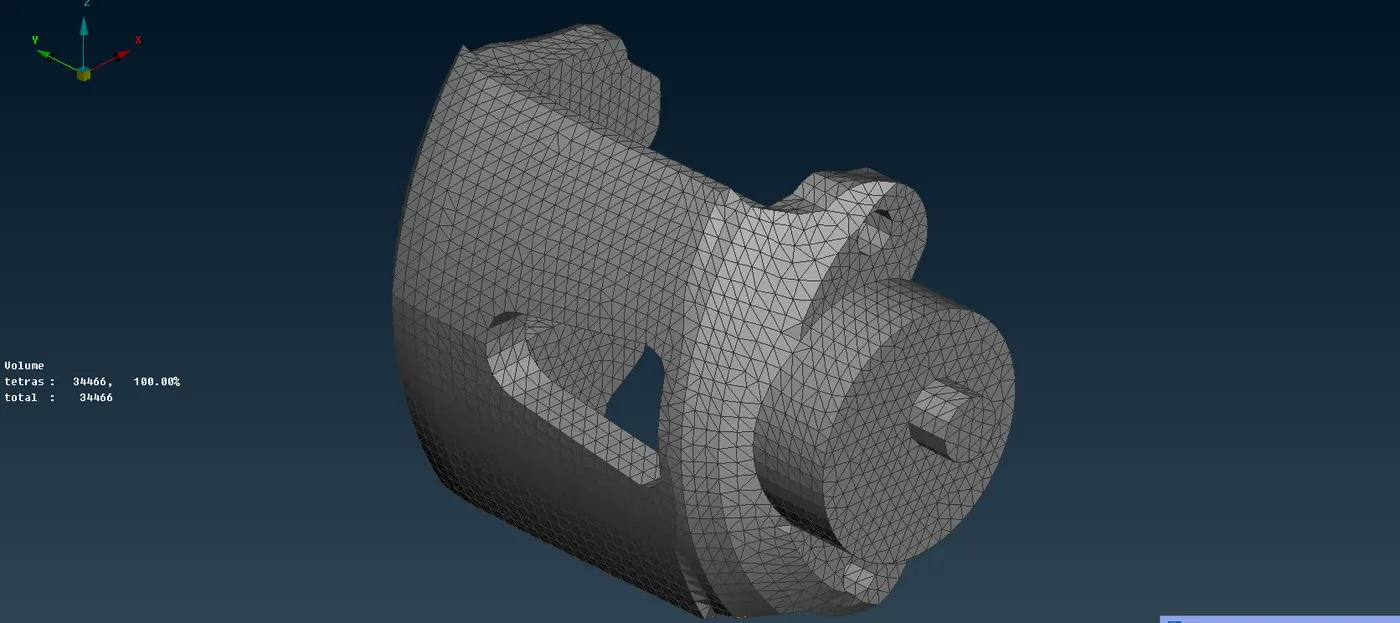
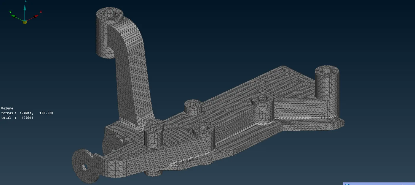
After the volume is defined, the surface meshing is done on the component’s surface with tria & ortho tria elements in the MESH module.
Ortho tria elements help to capture the features such as fillets, curves, etc. better than the tria elements. So these are used in curved and fillet areas in the model. Other flat areas can be meshed using tria elements itself.
It is advisable to use the ortho tria elements only in the curved & fillet regions as the computation time for ortho tria is considerably more than that of a tria element. As a result, meshing the whole model with ortho tria elements would make the computational time for the whole model very high which may sometimes lead to the crashing of ANSA application. In order to prevent this we will use ortho trias for meshing only the fillet & curved surfaces.
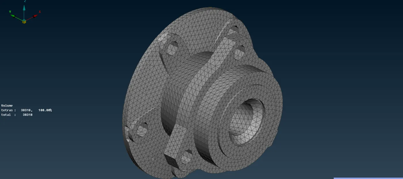
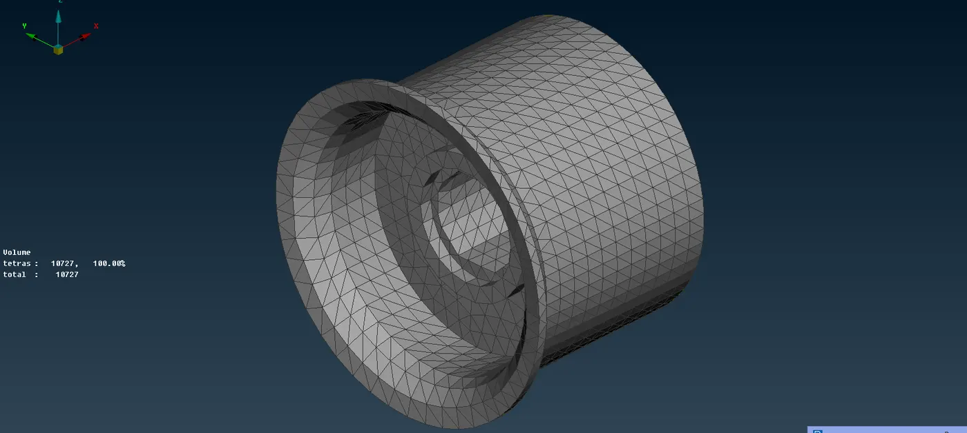
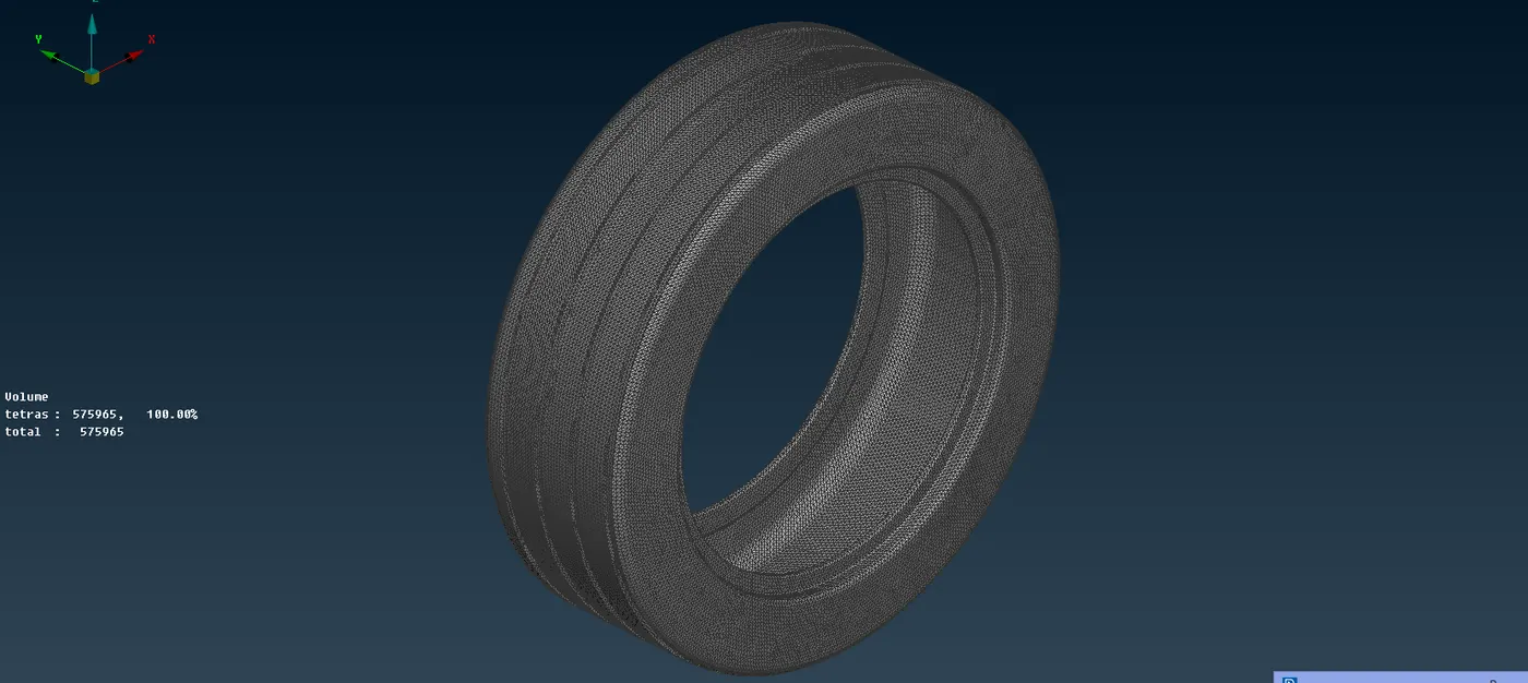
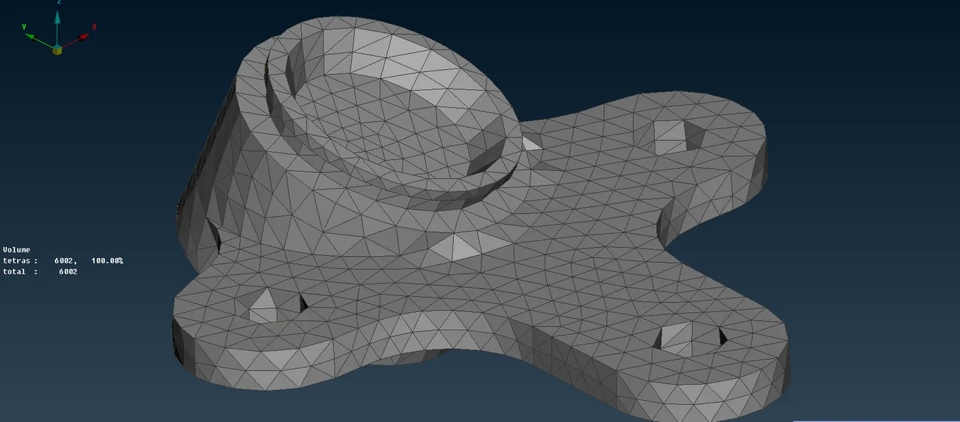
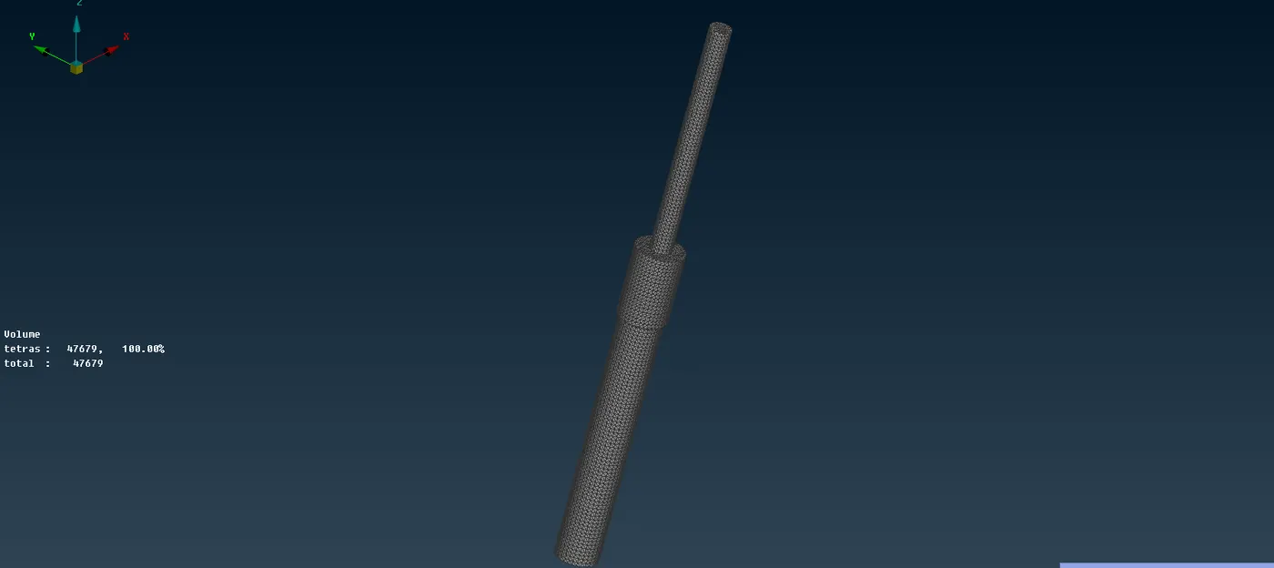
Once the surface meshing is done, the Volume meshing must be done. In the Volume mesh module, under VOLUMES -> LIST, the volume is selected and meshed.
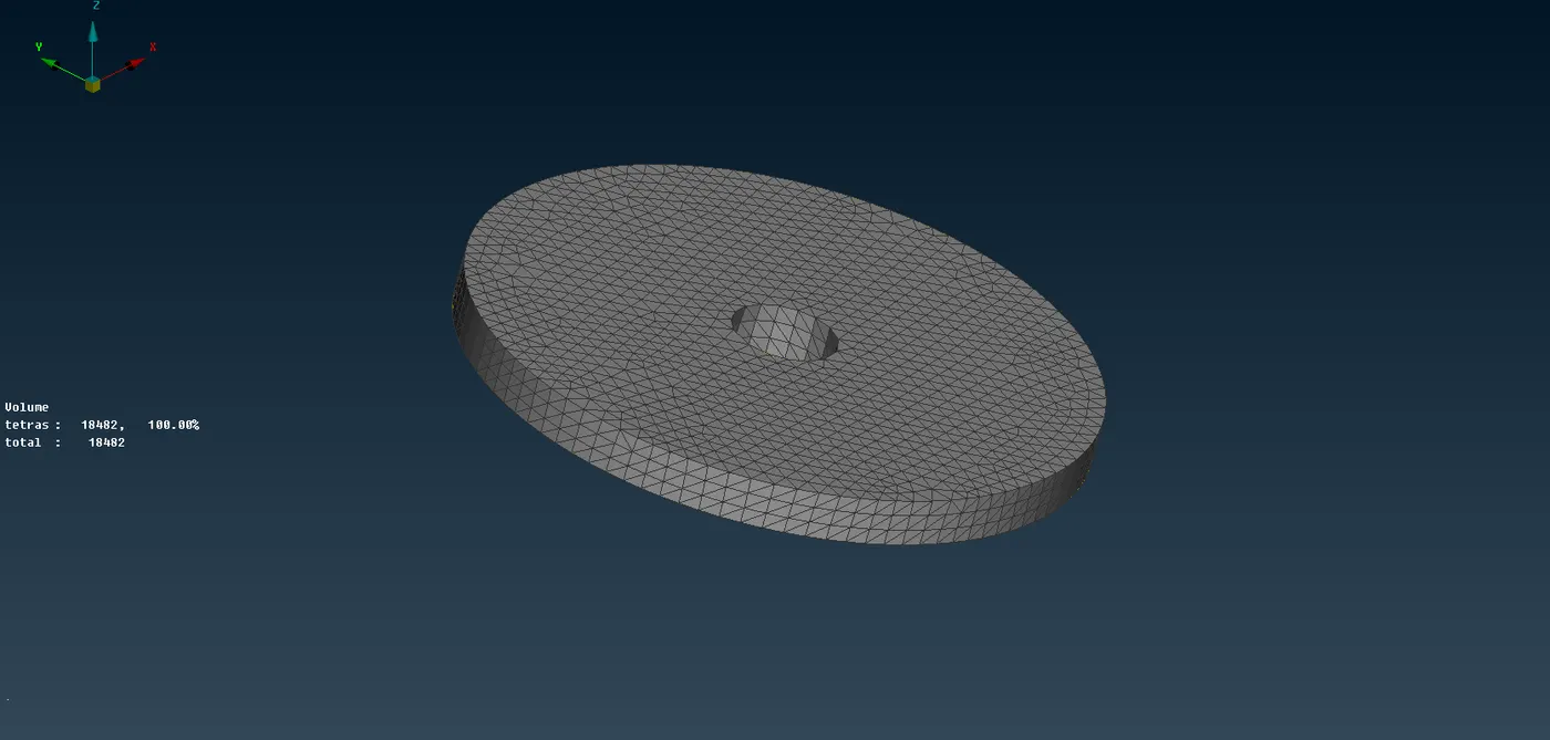
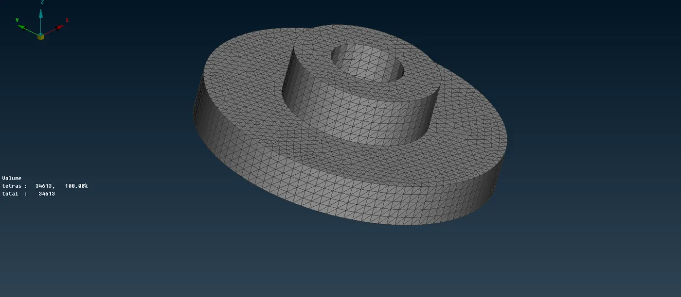
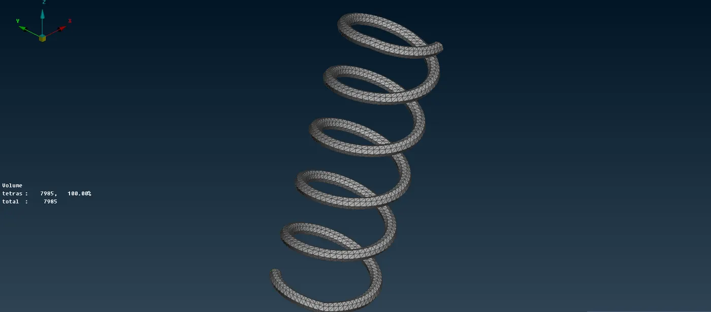
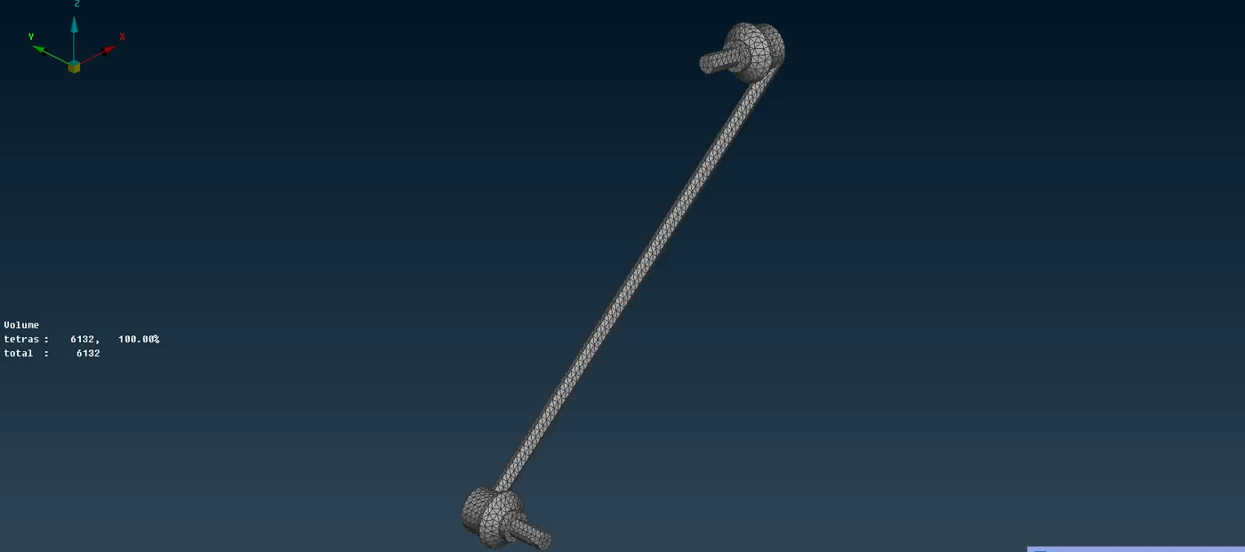
After the solid meshing is done, the Geometry & FE model are switched off so that the Volume mesh alone is visible.
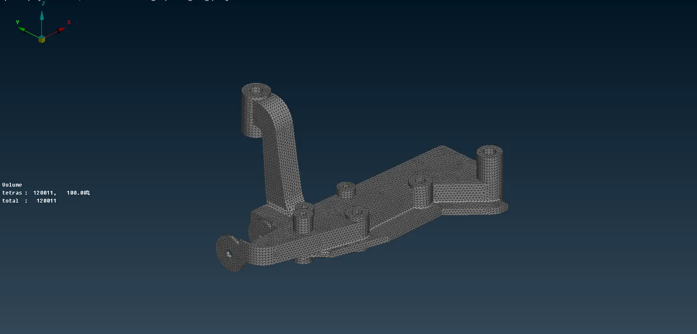
This way, the components are separated and meshed one by one.
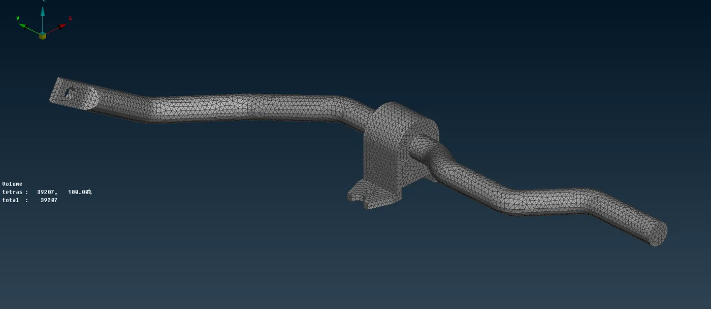

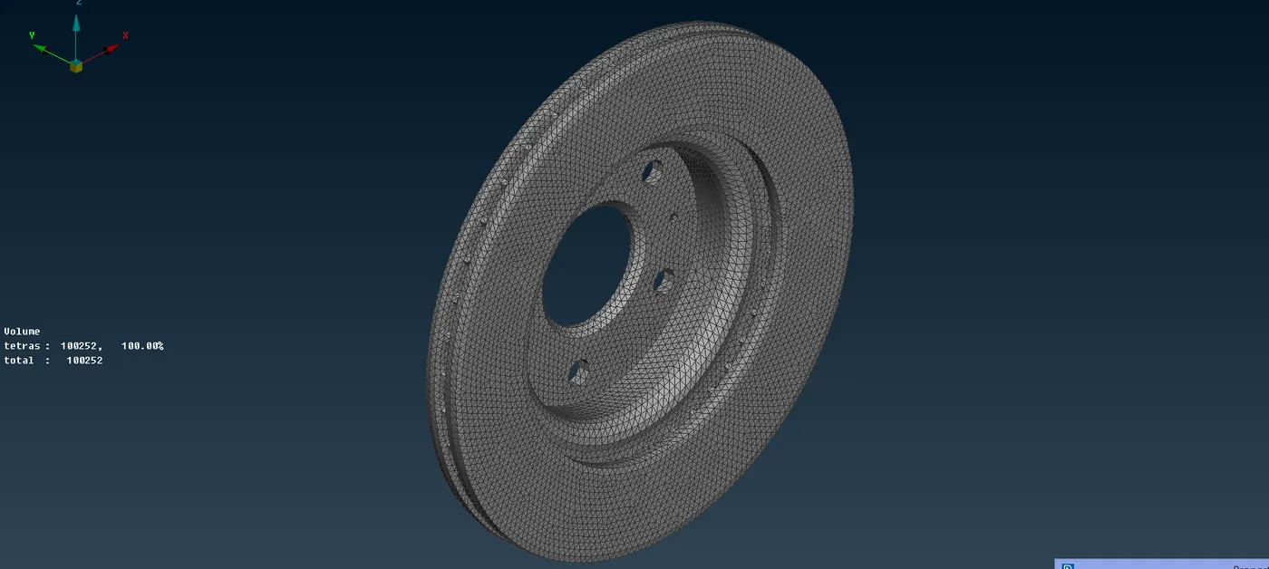
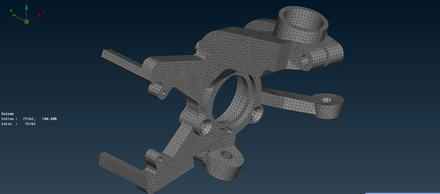
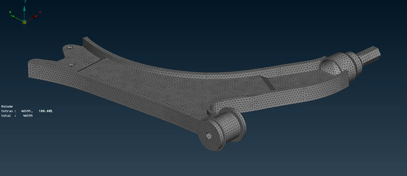
RESOLVING TET COLLAPSE & OTHER QUALITY ISSUES:
Solid mesh:
Once the meshing is done, the quality issues are seen in the Hidden mode. Tetra collapse or Tet collapse is a main quality issue which occurs in Volume mesh.
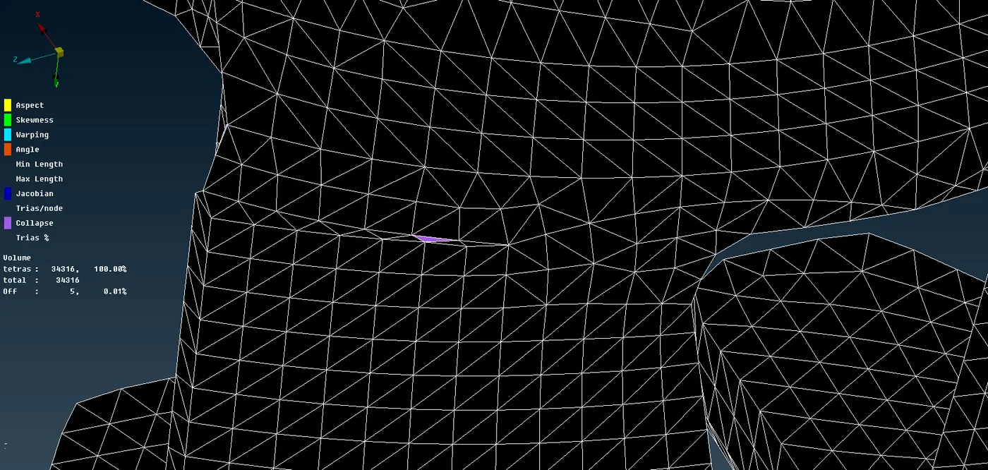
Tetcollapse is defined as the Min. of the quotient obtained by dividing the height of tetra element with the square root of area of the opposite face.
Tetra collapse = (Min. of h/√A) ÷ 1.24
where,
h = Height of the tetra element from the node to the opposite face
A = Area of the opposite face
The h/√A value is taken for all the 4 nodes and the minimum of that value is divided by 1.24 to obtain the tetcollapse value for that tetra element.
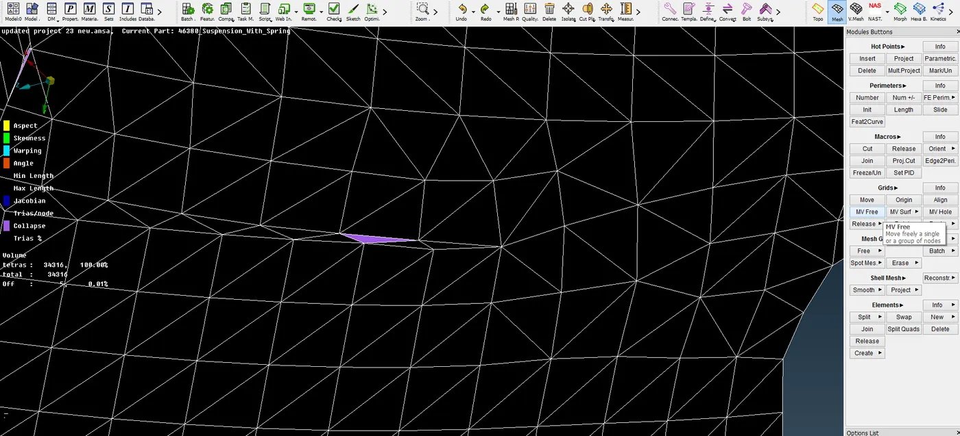
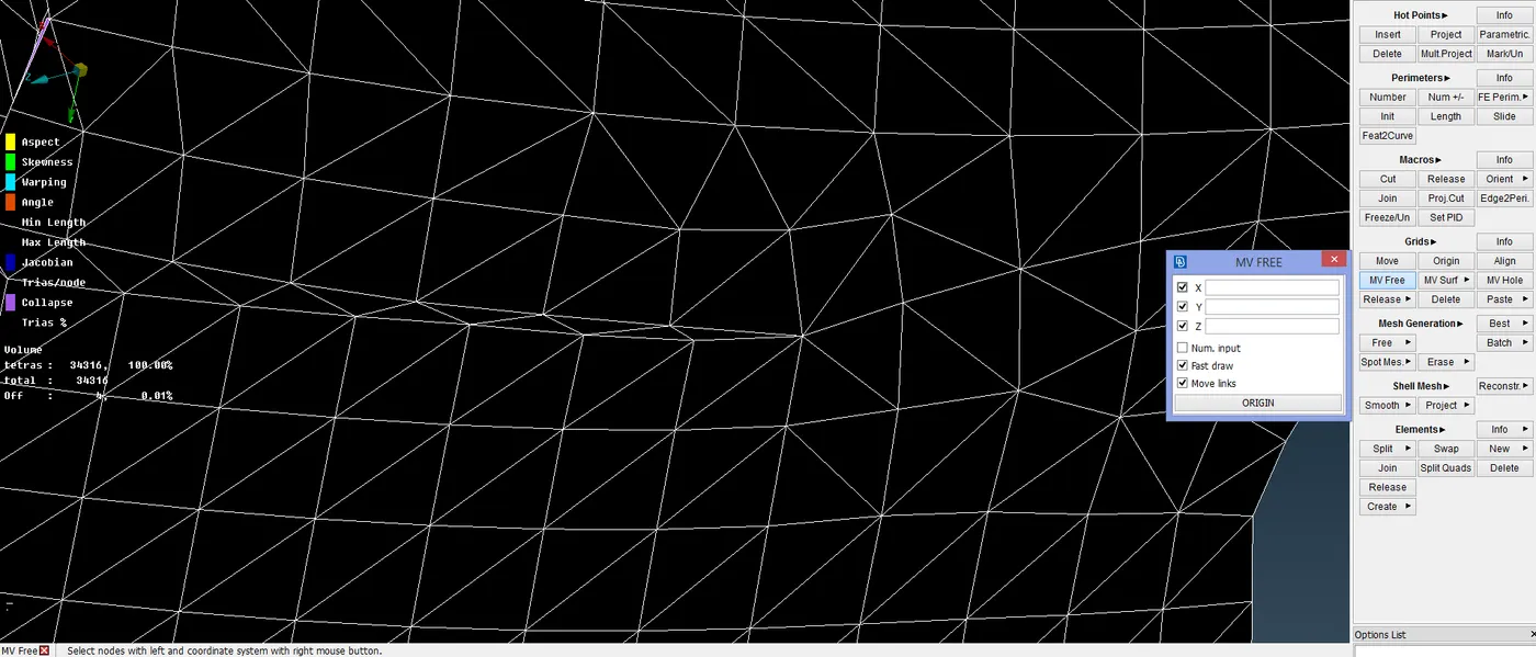
These issues should not be left un-resolved. The tetra element which is failing is selected and isolated. Then the nodes of the tetra element are moved in x, y & z directions using the GRIDS -> MV. FREE command in the MESH mode.
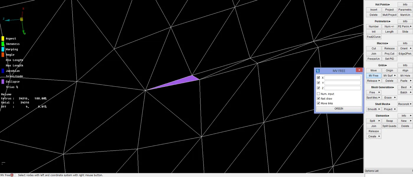
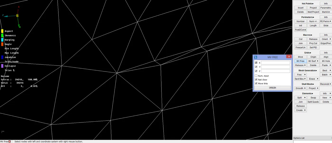
After the failing elements are fixed, the volume mesh model should be visually inspected for kinks and raised edges. Kinks are the dips in one or many nodes of the tetra elements from the surface of the mesh. Raised edges, as the word means, are the raising of one or many nodes of the tetra elements from the surface of the mesh.
These types of kinks & raised edges should not be present in the model and they should be cleared.
Shell mesh:
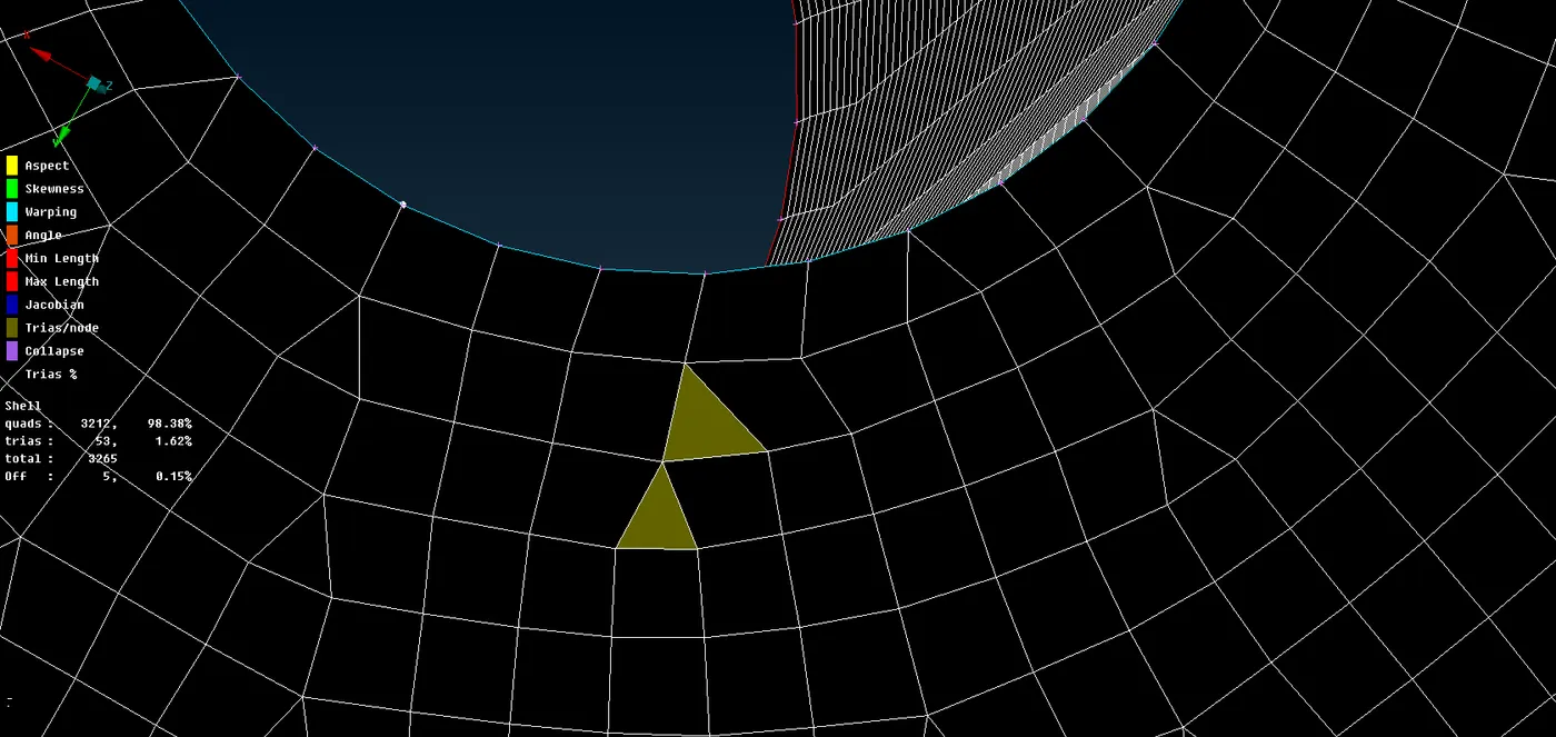
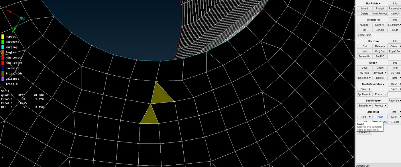
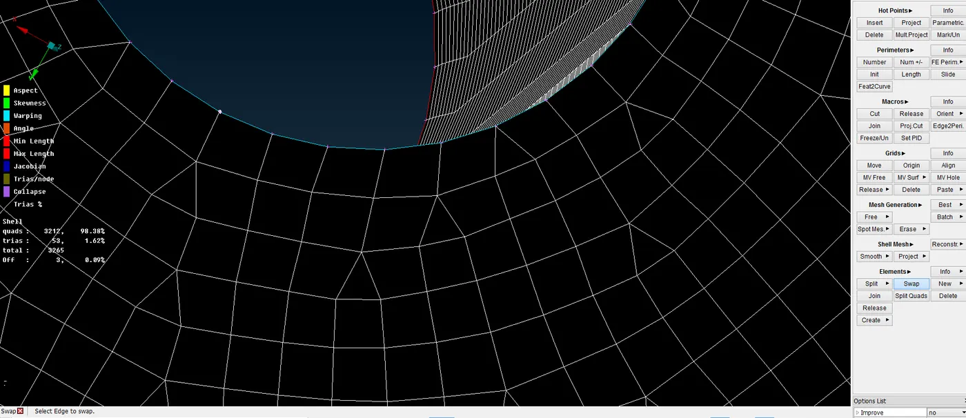
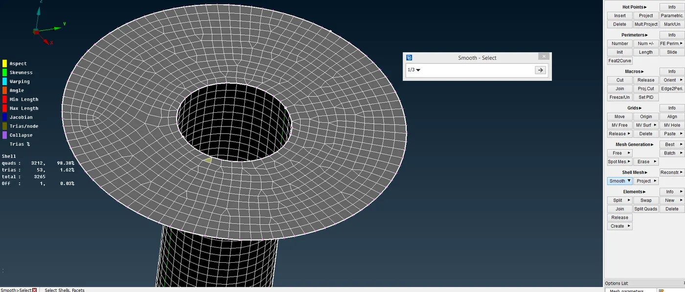
Similar to the solid meshing, the elements failing for quality in shell mesh can be seen only in the hidden mode. The mesh can be reconstructed using the SHELL MESH -> RECONSTRUCT command and smoothened using the SHELL MESH -> SMOOTH command in the MESH mode.
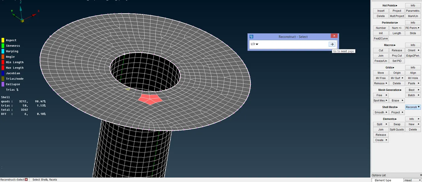
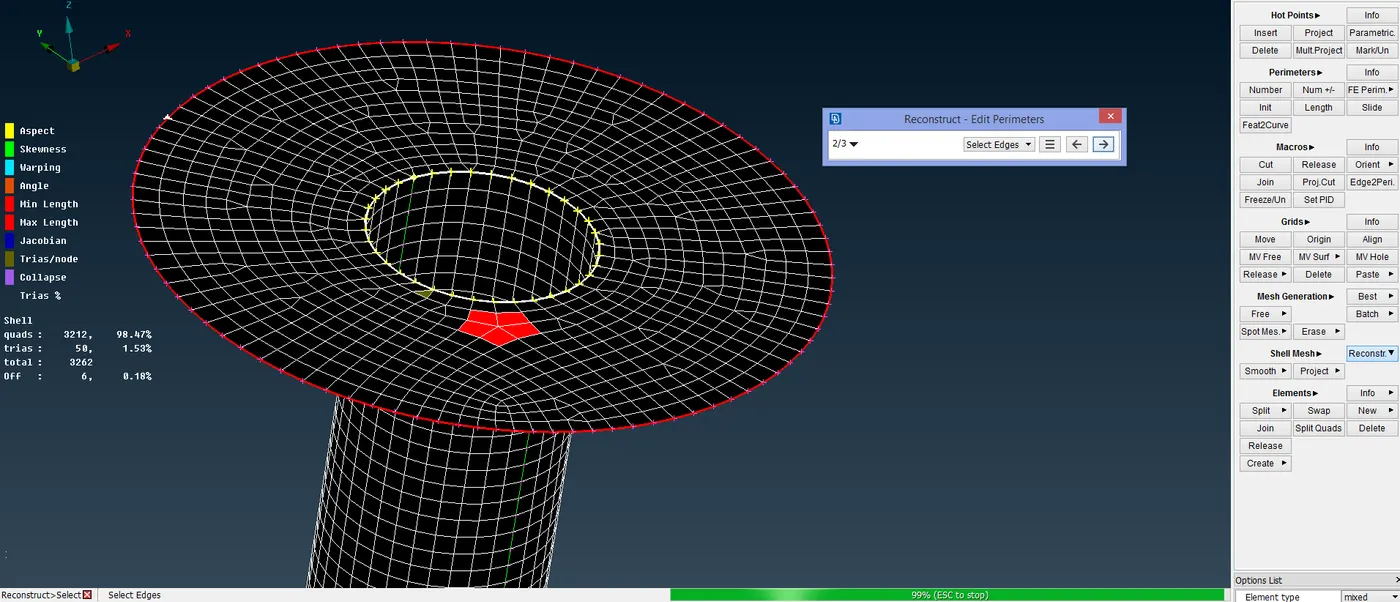
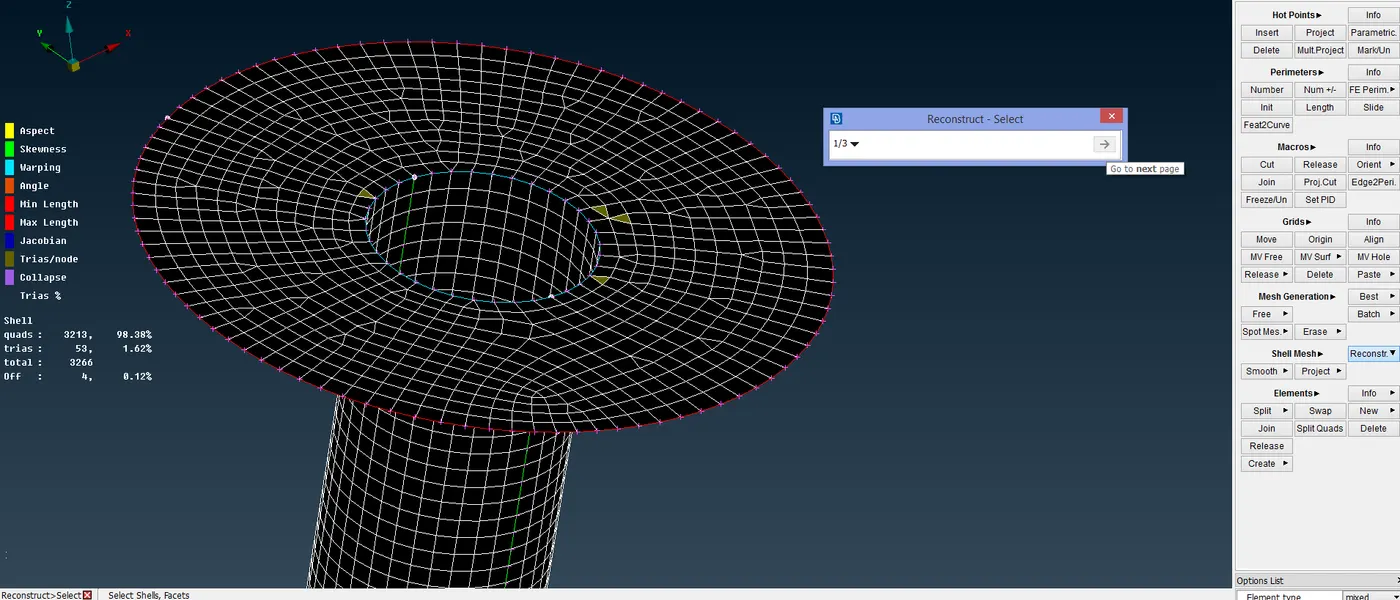
The tria elements can be split, swapped and joint using the ELEMENTS -> SPLIT, ELEMENTS -> SWAP and ELEMENTS -> JOIN commands in the MESH mode.
DEPLOYING CONNECTIONS:
Connections are deployed in the NASTRAN deck module. There are many types of connections available. They will be used and deployed depending on the model and the instance where it is used.
Rigid Body Element (RBE2):
As the name suggests, this is a type of connection which makes the selected nodes rigid and prevents movement with respect to the translational & rotational x, y, & z axis. This type of connection is generally called as RBE2. It is of two types, Many node RBE2 and Two node RBE2. The RBE2 command is in the NASTRAN deck module under ELEMENTS module button.
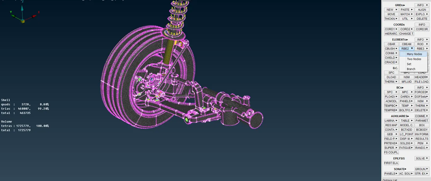
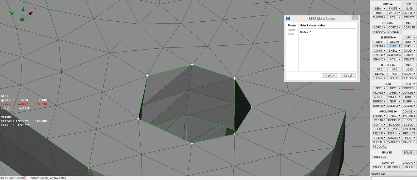
The nodes of the mesh element are selected and upon accepting the many node-RBE2 connection is deployed.
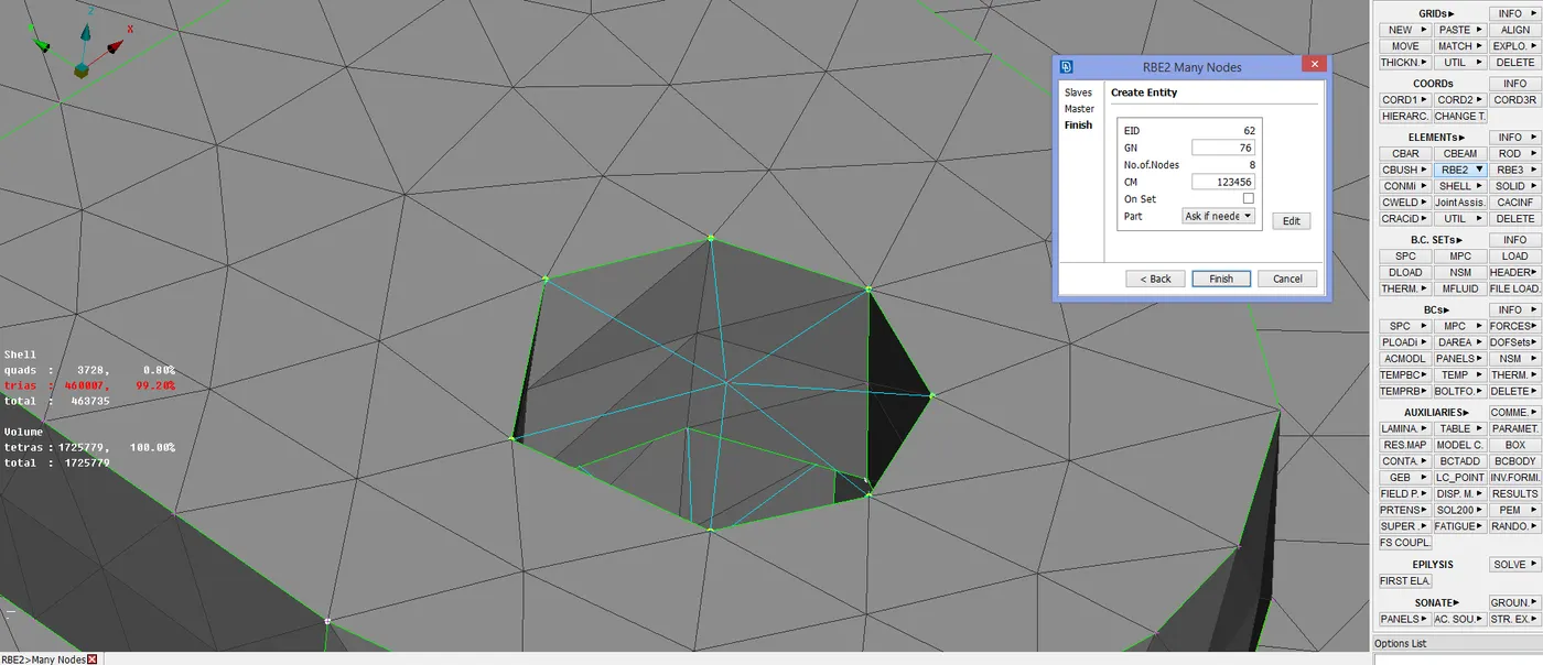
For nut-bolt representation, the two node-RBE2 connection is deployed.
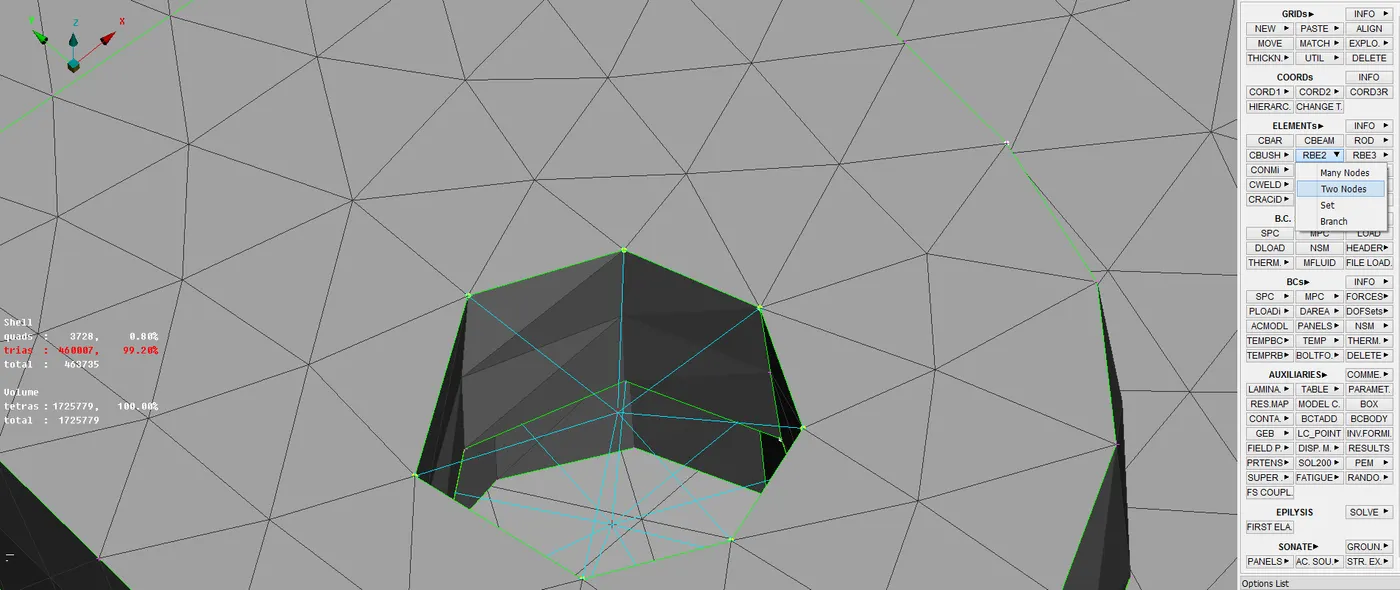
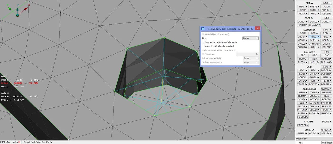
It is given between two many node RBE2 connections by selecting the two master nodes.
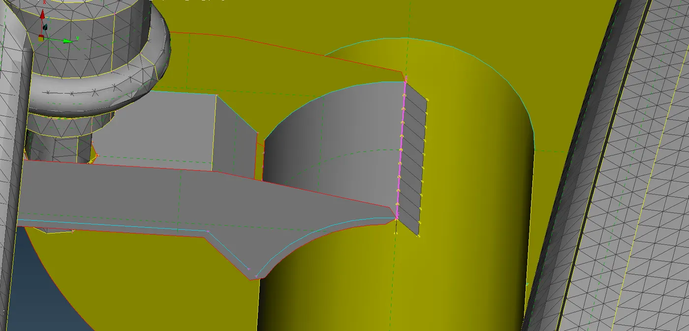
Weld connections are also given in the model. The weld line is created by converting the single cons to curves using the CURVES -> CONS2CURVES command in the Topo module.
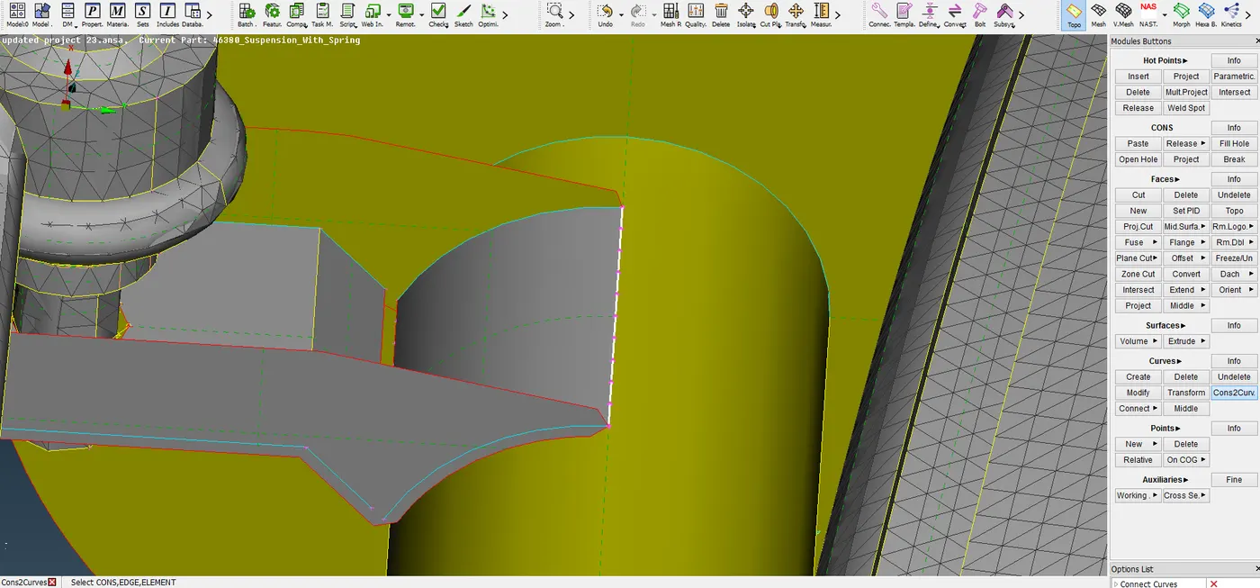
Then the curve is converted to seam line using the CONVERT -> Curves command in the ASSEMBLY tab.
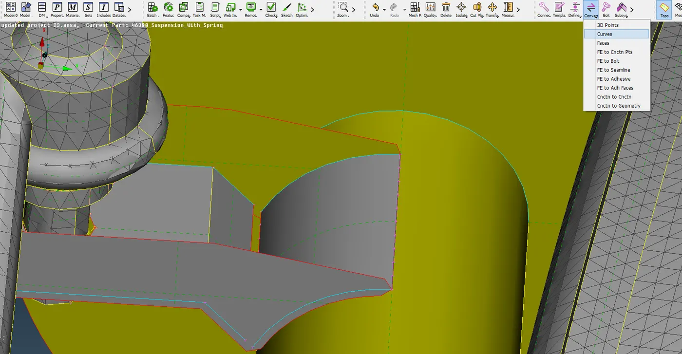
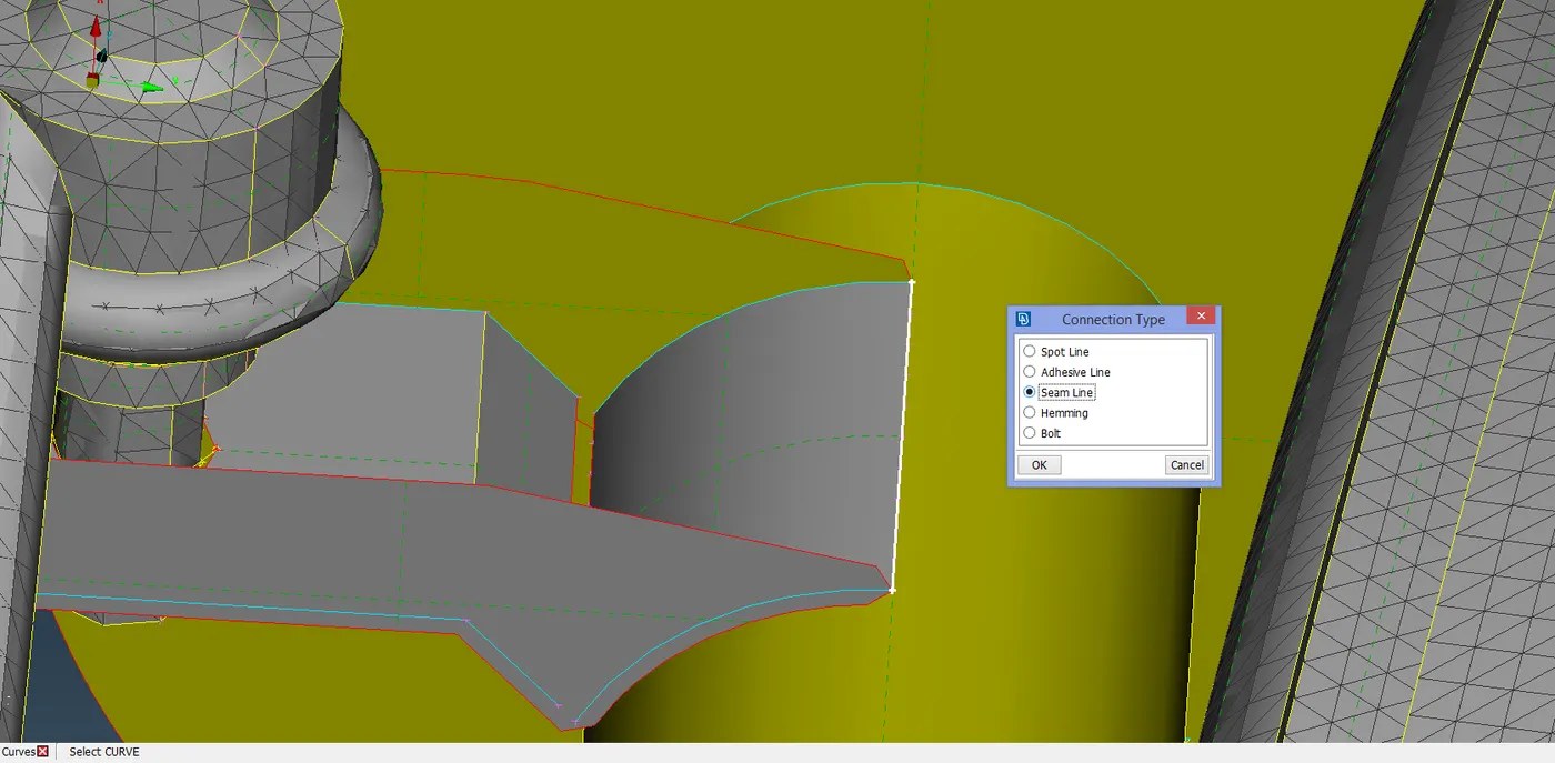
In the CONNECTION SELECTION ASSISTANT dialog box, the weld line to which the connection is to be deployed is selected. The 2 components between whom welding is to be done is selected.
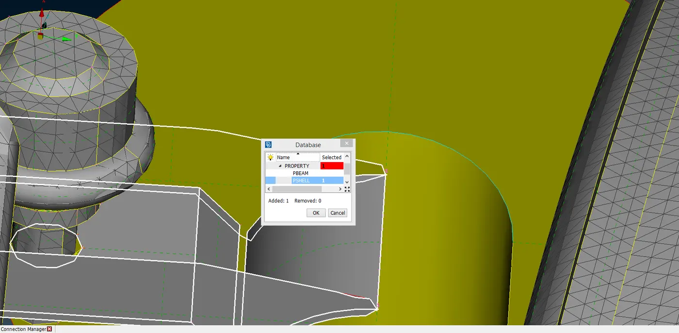
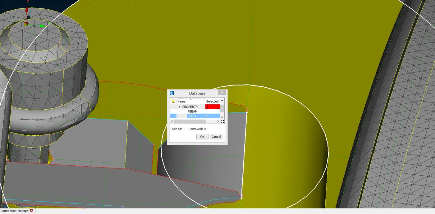
Then the search distance and base sheet are given along with the step length & width. A weld PID is also assigned to the weld FE.
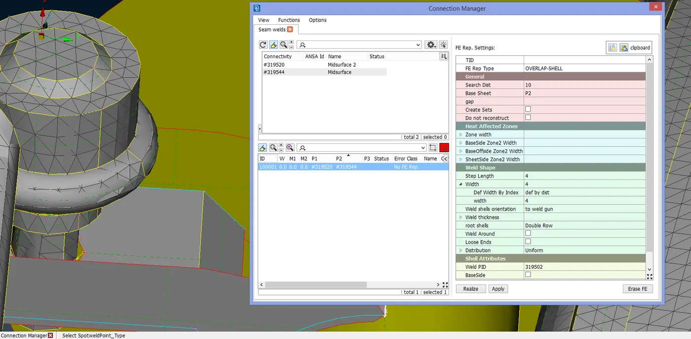
After applying, the connection is realised.
LEARNING OUTCOME:
In the above project, we have the following outcomes:
- Method of geometry clean-up on CAD models.
- Mid-surface extraction.
- Assigning property ID & set quality criteria.
- Shell meshing.
- Need for solid meshing and its method.
- Resolving tetra collapse & other quality issues.
- Deploying appropriate connections.
CONCLUSION:
Thus the given suspension model of a passenger car is meshed and the appropriate connections are deployed on the model.