Week-7 Challenge: DC Motor Control
AIM:
- To run MATLAB demo ‘Speed control of a DC motor using BJT H-bridge’ and modify the model such that armature current doesn’t shoot up when motor changes direction from forward to reverse.
- Compare Four-Quadrant Chopper DC Drive (DC7) and H-bridge.
- Make a suitable EV model using the DC7 block.
OBJECTIVE:
To learn about the operation of BJT H-bridge and Four quadrant chopper DC drive (DC7).
GOVERNING EQUATION:
Vehicle load characteristics equation
`T = 24.7 + 0.0051w^2`
MODEL SETUP:
1. Speed control of a DC motor using BJT H-bridge:
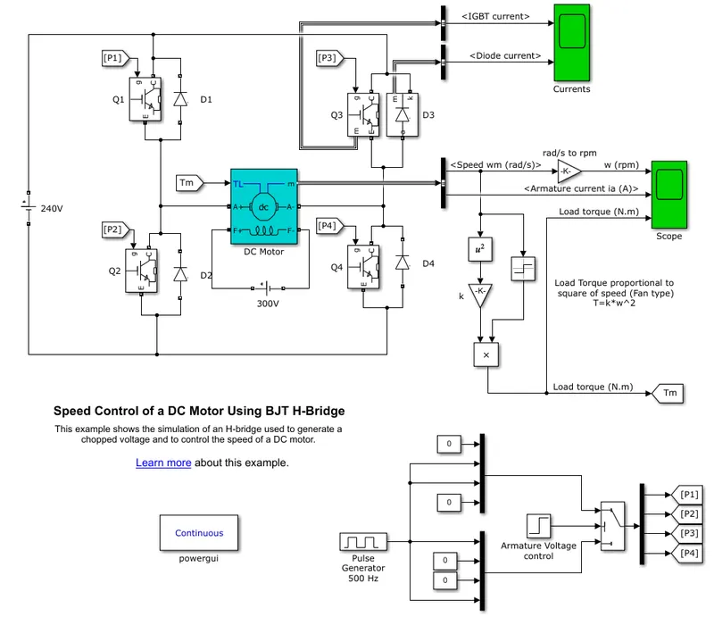
Here we have the speed control model using a H-bridge. A H-bridge consists of 4 BJTs (Bi-polar Junction Transistors) Q1, Q2, Q3 & Q4 and 4 diodes D1, D2, D3 & D4. The BJTs used consist of NPN transistors. A DC source power supply of 240 V is supplied. There is a DC motor used as load which is connected to a 300 V DC supply. The outputs from the DC motor are displayed using the scope.
3. EV model using DC7 block:
To make an EV model using the four-quadrant DC chopper DC drive (DC7), we take the example model from the MATLAB help and modify the model. The DC7 example model is shown below.
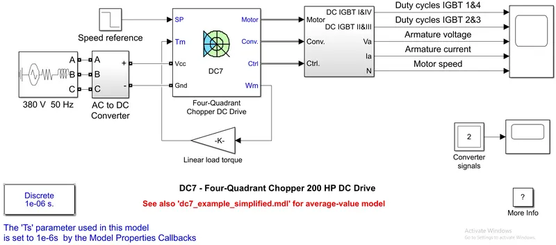
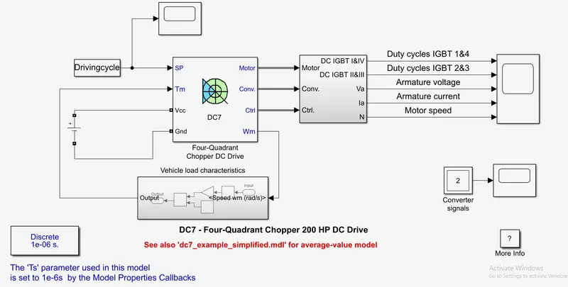
Instead of the step signal as input, we can connect a drive cycle block as input. Also a custom drive cycle can be fed by creating the velocity and time values in an excel spreadsheet. This can be fed using the from spreadsheet block. Another method to feed the driving cycle data is through the from workspace block. The driving cycle data is imported into the model workspace and then it is taken from the model workspace which is separate for each model. To replace the AC power supply and AC to DC converter, we can put a DC power source such as a Battery or a DC voltage source block. Instead of the linear load torque block, we can give the load characteristic equation of any real time motor. With this setup, we can create an EV model. After doing the modifications, we have the below model.
EXPLANATION:
1. Speed control of a DC motor using BJT H-bridge:
Speed control of the DC motor using BJT H-bridge is done using the example model from the MATLAB documentation. When the model is opened, we see the simulation time for 1 second. After simulating the model, we get the output plots.
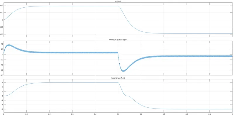
In the output plots, we can see that there is a huge loss in armature current. This can be seen from the huge blip in the armature current plot. This loss occurs when the switching is done. After the switching is done, the motor starts to run in the reverse direction. In this scenario, the pulse width is given as 75%, i.e. the duty cycle is 75%.
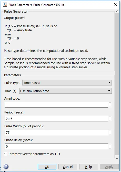
The input voltage is 240 V. So the effective voltage will be 180 V. This huge current loss is due to hard switching. This current loss in the armature can be avoided or reduced by changing the duty cycle. For this the pulse width has to be changed. The pulse width is changed in the pulse generator block.
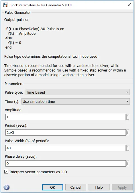
But once we change the pulse width (and in turn the duty cycle), the efficiency of the system will also change since the system is now functioning at 75% efficiency. So it should be balanced between compromising the efficiency of the system and minimising the current losses. By varying the pulse width, we can see the effect in the current losses. Finally, we arrive at the optimum pulse width for the pulse generator.
2. Comparison of Four-Quadrant Chopper DC Drive (DC7) block & H-bridge:
Four quadrant DC chopper drive (DC7):
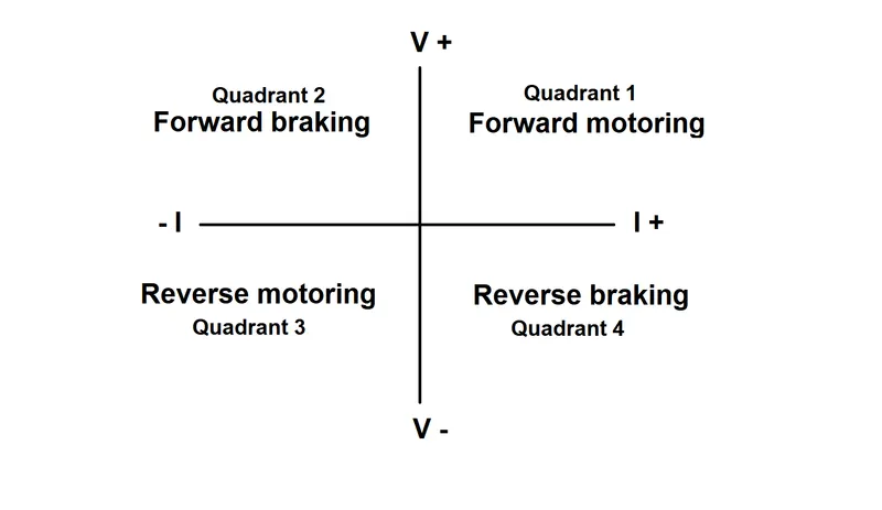
The Four-Quadrant Chopper DC Drive (DC7) block represents a four-quadrant, DC-supplied, chopper (or DC-DC PWM converter) drive for DC motors. This drive features closed-loop speed control with four-quadrant operation. The main advantage of this drive, compared with other DC drives, is that it can operate in all four quadrants (forward motoring, reverse regeneration, reverse motoring, and forward regeneration). The power can flow either from source to load or load to source in this chopper. In the first quadrant, a Class-E chopper acts as a step-down chopper whereas in the second quadrant it behaves as a step-up chopper.
The circuit diagram of a four quadrant DC chopper is shown below.
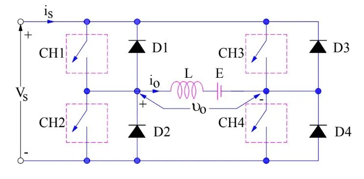
First Quadrant Operation: For first quadrant operation, CH4 is kept ON, CH3 is kept OFF and CH1 is operated. When both CH1 & CH4 are ON simultaneously, the load gets directly connected to the source and hence the output voltage becomes equal to the source voltage. This essentially means that vo = vs. It may be noted that the load current flows from source to load as shown by the direction of io. When CH1 is switched OFF, the load current free wheels through CH4 and D2. During this period, the load voltage and current remains positive. Thus, both the output voltage vs and load current io are positive and hence, the operation of the chopper is in the first quadrant. This operation is also called FORWARD MOTORING.
Second Quadrant Operation: To obtain second quadrant operation, CH2 is operated while keeping the CH1, CH3 & CH4 OFF. When CH2 is ON, the DC source in the load drives current through CH2, D4, E and L. When CH2 is turned OFF, current is fed back to the source through D1, D4. As load voltage Vo is positive and Io is negative, it is the second quadrant operation of chopper. Since, the current is fed back to the source, this simply means that load is transferring power to the source. This operation is also called FORWARD REGENERATIVE BRAKING.
Third Quadrant Operation: The current and voltage are assumed positive if their direction matches with what shown in the circuit diagram. If the direction is opposite to what shown in the circuit diagram, it is considered negative. For third quadrant operation, CH1 is kept off, CH2 is kept ON and CH3 is operated. When CH3 is ON, load gets connected to source and hence load voltage is equal to source voltage. But carefully observe that the polarity of load voltage vo is opposite. Hence, vo is negative. Now, when CH3 is turned OFF, the negative load current free wheels through the CH2 and D4. In this manner, vo and io both are negative. This operation is also called REVERSE MOTORING.
Fourth Quadrant Operation: CH4 is operated while keeping CH1, CH2 and CH3 OFF. When CH4 is turned ON, positive current flows through CH4, D2, L and E. When CH4 is made OFF, current is fed back to the source through diodes D2, D3. Here load voltage is negative but the load current is always positive. Here, power is fed back to the source from load. This operation is also called REVERSE REGENERATIVE BRAKING.
H-bridge circuit:
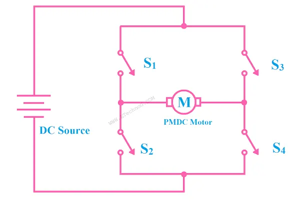
A H-Bridge Circuit is the connection of switches(generally four switches) in such a manner we can change the polarity of the voltage applied to a load and the circuit looks like the capital letter 'H'. The circuit has four switches. In the left side of the load, two switches are connected in series and in the right side of the load two switches are connected in series.
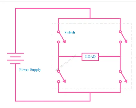
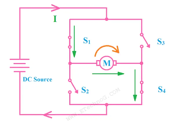
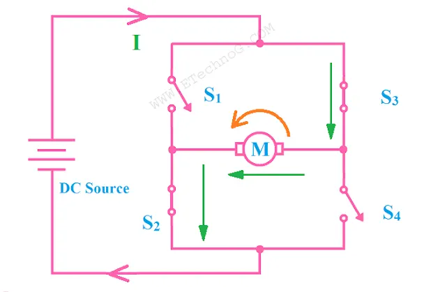
The H-Bridge circuit is mainly used to change the polarity of the voltage applied to a load. We have taken a PMDC motor as a load and the PMDC motor is connected with the H-Bridge circuit. if we change the polarity of the applied voltage applied to the PMDC motor then the rotation of the motor will be changed and it can be done by the H-Bridge circuit. In the H-Bridge circuit, four switches are connected named as S1, S2, S3, S4.
Case 1: When switch S1, S4 are closed and S2, S3 are open then the positive voltage will be applied across the motor and the motor will be run in the forward direction.
Case 2: When switch S2, S3 are closed and S1, S4 are open then the negative voltage will be applied across the motor and the motor will be run in the backward direction.
Applications: The most important application of H-bridge circuits is the motor driving. So it is used in motor driving circuits. It is used in robotics for driving the motors in forward and reverse direction according to the need. H-bridge circuits are also used in inverters. In EVs, they are used in battery charging circuits.
3. EV model using DC7 block:
The load characteristics of the motor for the model is set using the experimental values of a typical motor. This is done by creating a sub-system. The blocks required for creating the equation are set. Then these blocks are compressed into a sub-system. Since the driving cycle is for 100 seconds, the simulation time is also set for 100 seconds. Now the simulation is started. After the simulation has run for some time, we can see the plots to see the output characteristics and other motor parameters.
RESULTS:
1. Speed control of a DC motor using BJT H-bridge:
Pulse width 50:
With a pulse width of 50, the duty cycle is also reduced to 50%, i.e. 120 V. The output plot obtained is as follows.
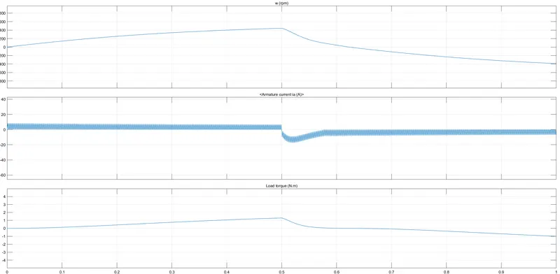
Here we can see that the current loss has been reduced as that compared to a pulse width of 75. But still there is significant current loss.
Pulse width 45:
Reducing the pulse width to 45, the duty cycle is also reduced to 45%, i.e. 108 V. The output plot obtained is as follows.
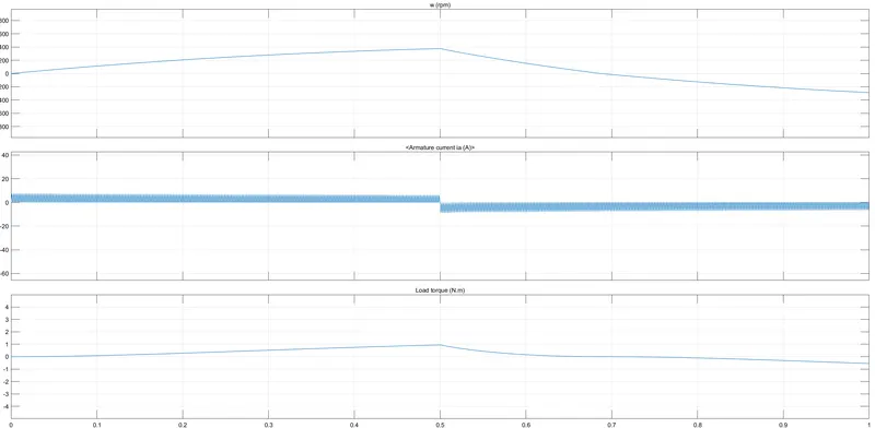
Here we can see that the current loss has been reduced as that compared to a pulse width of 50. But still there is significant current loss. So we reduce the pulse width further.
Pulse width 40:
Now with pulse width 40, the duty cycle is also at 40% at 96 V. The output plot obtained is as follows.
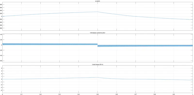
Here we can see that the current loss has been reduced as that compared to a pulse width of 45. But still there is a small current loss. So we reduce the pulse width further down.
Pulse width 35:
With pulse width of 35, the duty cycle is at 35% at 84 V. The output plot obtained is as follows.
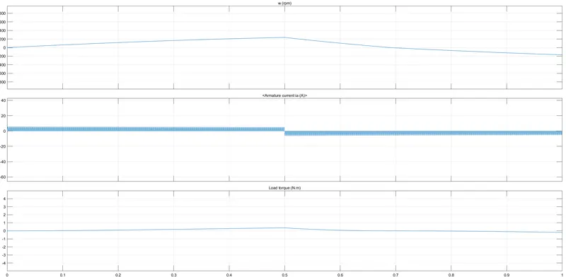
Here we can see that the current loss has been reduced but there is no significant difference between this scenario and the previous scenario. So it would be better to have the pulse width at 40.
3. EV model using DC7 block:
From the scope block, we can see the output plots.
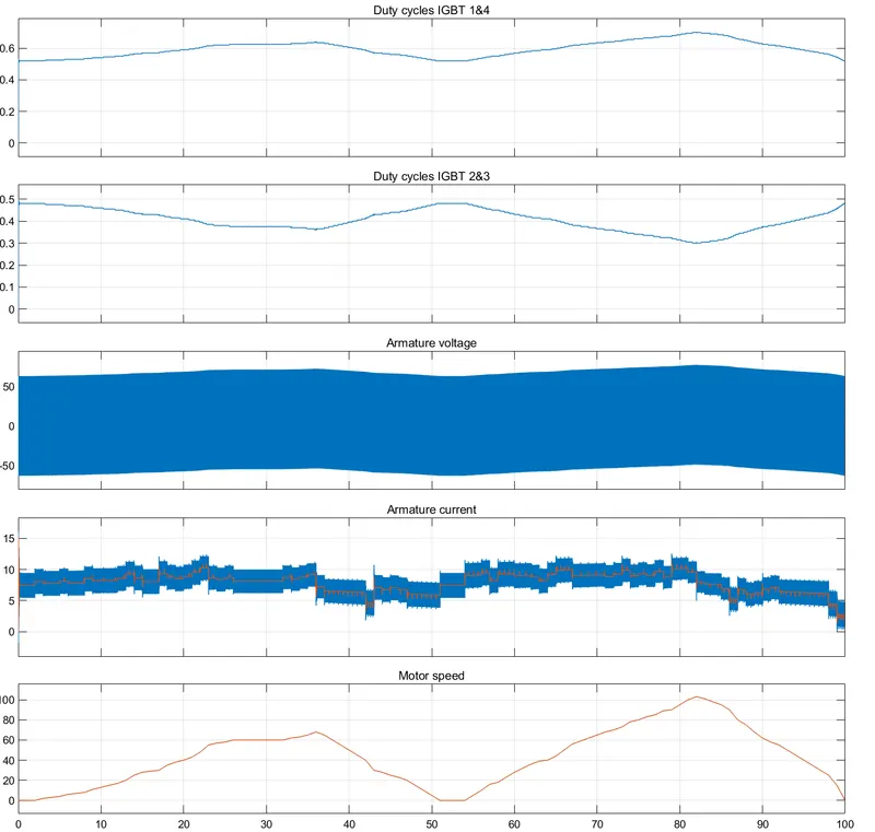
First we have the duty cycles of the IGBT 1 & 4. Then the duty cycles of IGBT 2 & 3. Below that is the Armature voltage and armature current. In the last, we have the motor speed. We can see the duty cycle of the IGBT 1 & 4 are increasing & decreasing in a zig-zag fashion and for IGBT 2 & 3 it is opposite. Zooming in the armature voltage, we can understand the plot better. The armature current is like a step function. The armature voltage can be seen varying from 3 to 12 in the y-axis. Finally, the motor speed can be seen in the last plot. It can be noted that the graph of the motor speed is matching with the driving cycle plot.
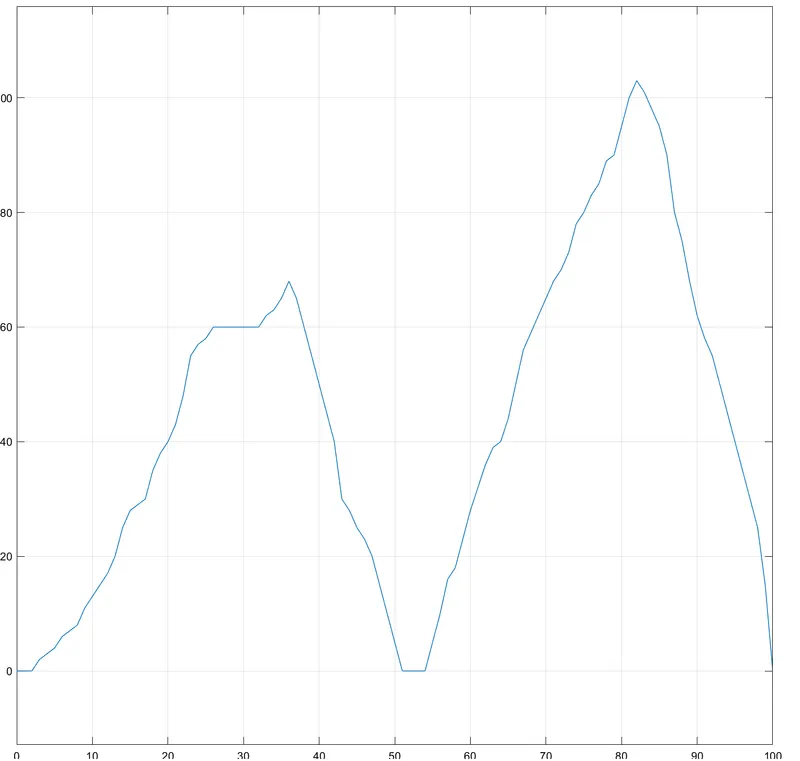
So we can stay assured that the motor is performing in the right way for achieving the speeds in the driving cycle.
CONCLUSION:
- Thus the modification of the BJT H-bridge model is done to reduce the armature current loss when the motor direction changes.
- The comparison between 4 quadrant DC chopper drive and H-bridge is done and explained.
- An EV model is done using the DC7 block in Simulink.