Assignment 2-RADIOSS Engine File Editing & 3D Meshing Challenge
AIM:
AIM:
1. Radioss engine file:
1) Check the material properties of the rail component and calculate the speed of sound in steel rail=_______
2) The length of the rail is about 1000 mm. Calculate the time taken for a shock wave to travel from one end of the rail to the other.3)
3) Time for sound to travel length of rail=______
4) Edit the engine file so that the stress wave can be monitored, moving from one end of the rail to the other during impact - this will require a termination time equal to the time it takes for the sound to travel the length of the rail(set on/RUN card)
5) Set the frequency of animation output to a time that will give 20 animation steps(/ANIM/DT)
6) Change /print -10.
2. 3d meshing - tetra mesh and hex mesh:
- To mesh the given components with given quality criteria
OBJECTIVE:
The objective of the assignment is to get familiar with the radioss engine file, its syntax and the values in the engine & starter file.
MODEL:
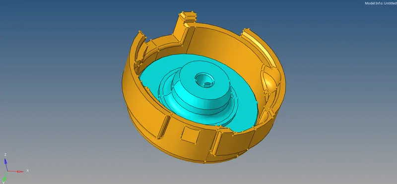
Housing model:
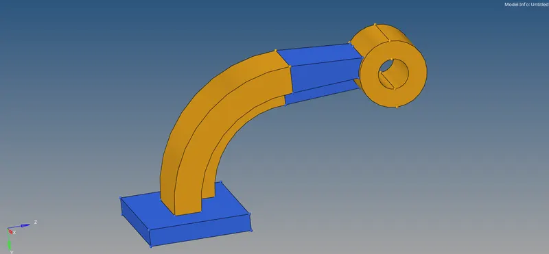
Arm bracket model:
GOVERNING EQUATION:
Speed of sound is given by`c = E/rho`
where,
`E =` Young's modulus of elasticity
`rho =` Density
PROCEDURE:
- Radioss engine file:
In Radioss there are two files, namely Starter file & Engine file. The starter file contains the information about the model, boundary conditions, etc. In the starter file, the file begins with /BEGIN and the file name (FIRST_RUN in this case).
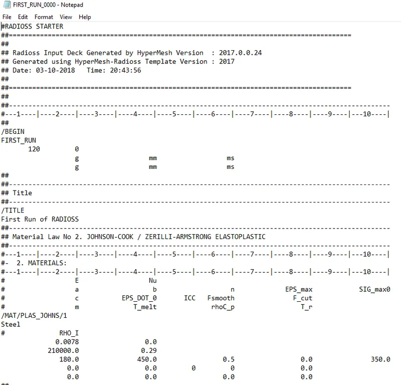
Then there are the units of the quantities for input and output. After that are the material properties such as property card, Young’s modulus, poisson’s ratio, etc.
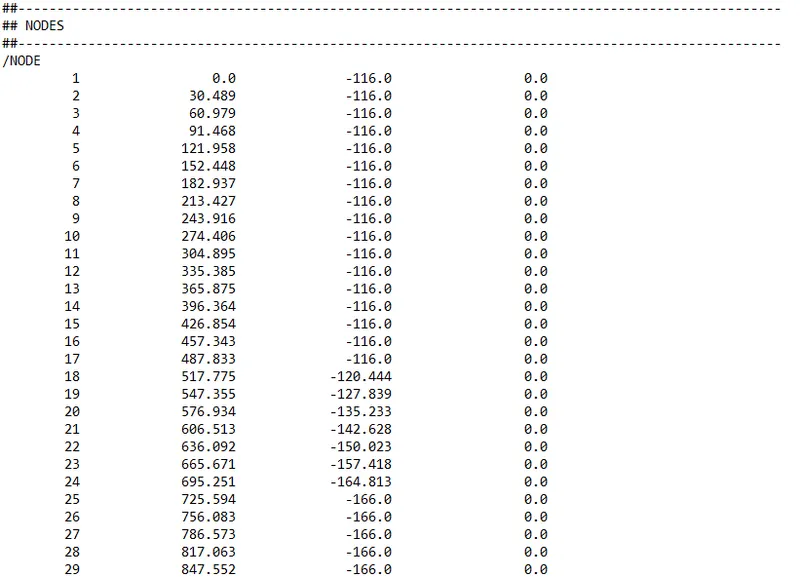
Then there is the node ID & coordinates of the node (x,y,z).
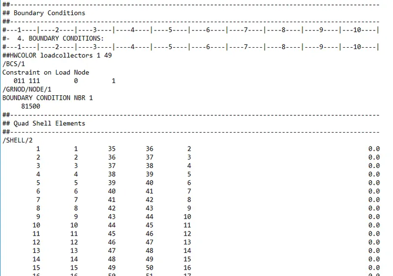
Following that are the boundary conditions.
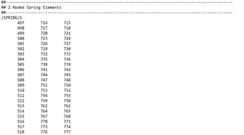
After the boundary conditions, if there are any connectors, their related information is given.
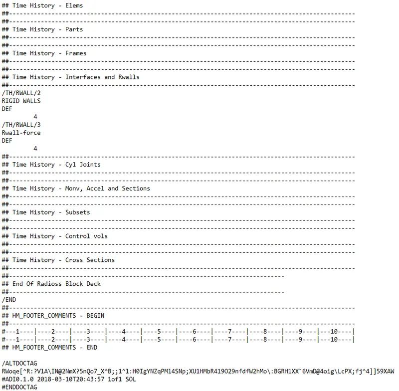
At last, the file is completed with an end tag.
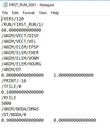
The engine file contains information about the time step and other information.
Calculations:
1)
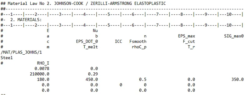
From the material properties of the rail component,
Density `rho= 0.0078 g/(mm^3)`
Young's modulus of elasticity E = 210000 GPa
Poisson ratio = 0.29
Speed of sound is given by`c = E/rho`
where,
`E =` Young's modulus of elasticity
`rho =` Density
`implies c= 210000/0.0078`
`implies 5188.74 (mm)/(ms)`
2)
The length of the file is given as 1000mm. The speed of the sound is calculated as 5188.74 mm/ms. The time taken to travel through the rail is
t = 1000/5188.74
t = 0.19 ms
3) Time for sound to travel length of rail = 0.19 ms
4)
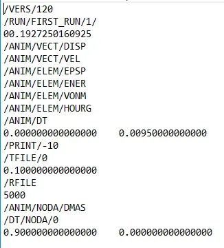
The termination time is essentially the total time the solving will happen. So it is the time taken to travel through the rail, which is 0.19 ms.
5)
To set the frequency of the animation output, we will need to consider the total solving time. The frequency of the animation output is the time for which every snapshot is taken during the solving. For example, if the frequency is 1, the snapshot is taken for every 1 time unit.
In this case, the total solving time is 0.19ms. To take 20 snapshots, we need frequency as
f = 0.19/20
f = 0.0095
6)
Tetra meshing:
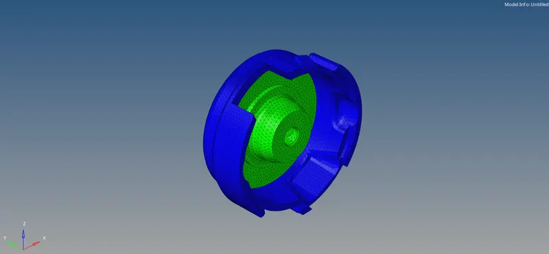
First the model is imported. Then the surface meshing is completed first with tria elements.
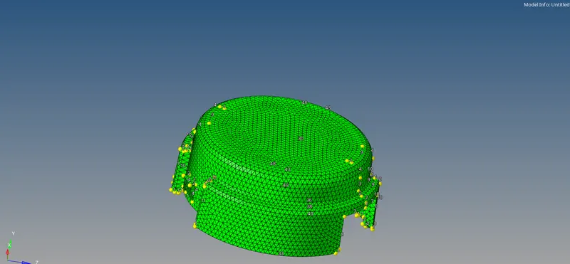
After the surface meshing is completed, the tetra mesh is generated using the tetramesh command in the 3d panel.

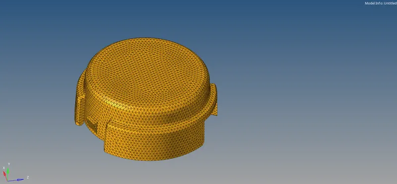
By masking some elements, the mesh can be verified.
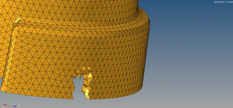
The same procedure is followed for the other component.
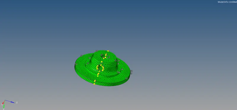
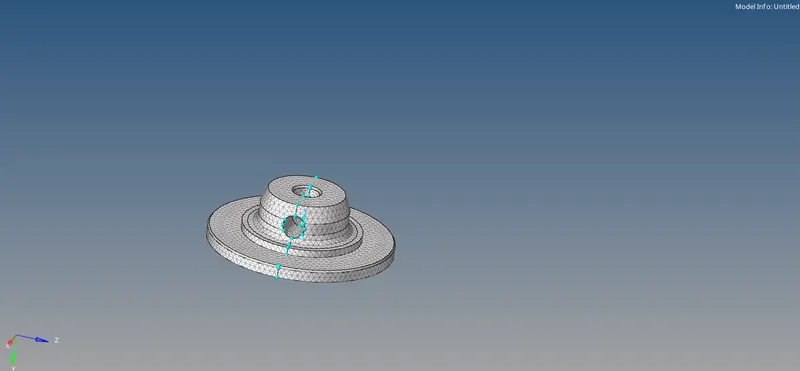
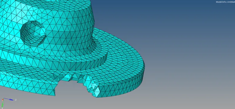
After meshing is completed, the elements are checked for tet collapse using the check elements. It is ensured that all the elements pass the tet collapse of 0.15 and no elements fail.
Hexa meshing:
First the model is imported. Then the surface meshing is first completed on the base with only quad elements.
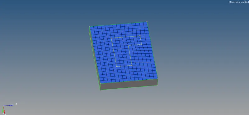
This mesh is then used as line drag to create hexa elements in the base component.
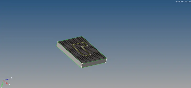
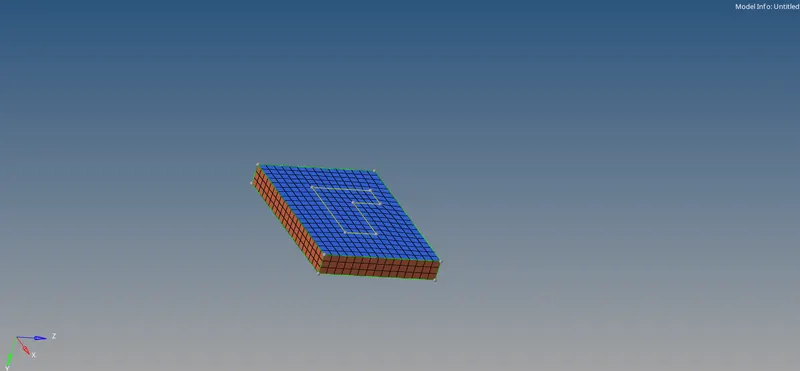
Some elements are masked to check the mesh.
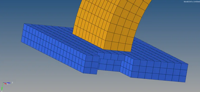
Then the hexa meshing is done for the arm curve. For this, a mid node is created using the curvature of the arm curve.
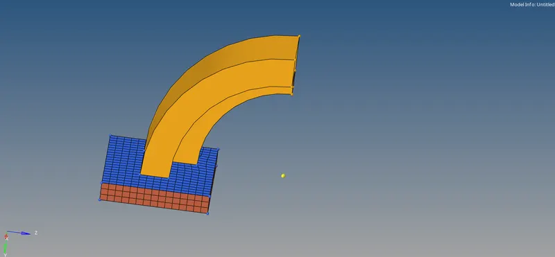

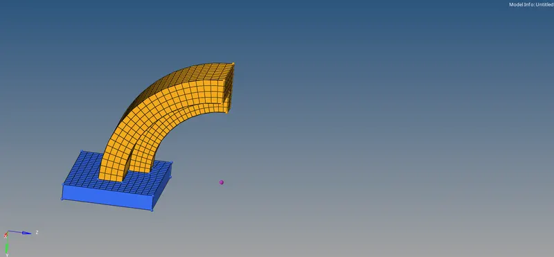
Then the shell elements are selected and the spin command is used to create hexa elements inside the arm curve. Some elements are masked to check the mesh.
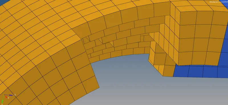
For arm straight, we need to use another method. We select the arm curve and extract shell elements on the face of it using the faces command.
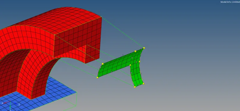
On the other side of the arm straight, shell meshing is done with quad elements. The number of shell elements on both the sides of the arm straight are to be matched exactly.
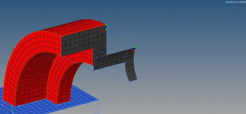
Then the command is used to create hexa elements.
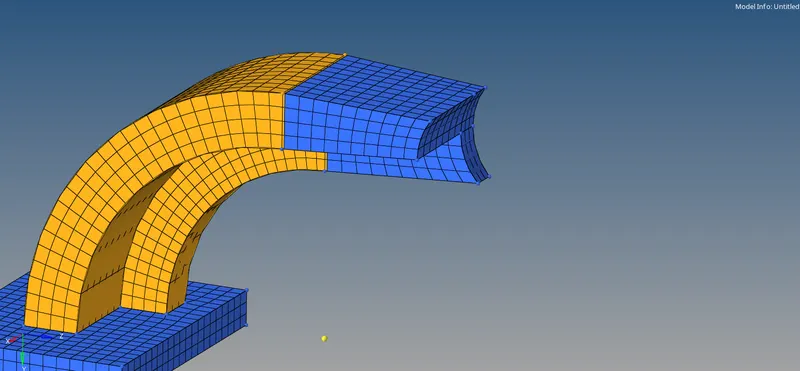
Some elements are masked to check the mesh.
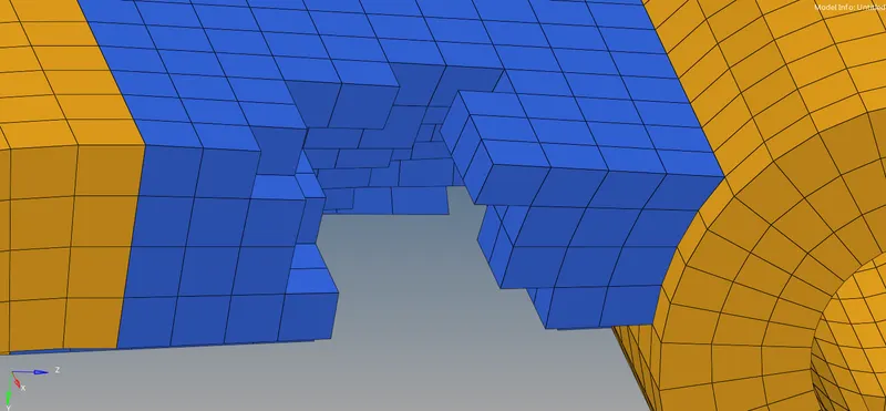
For boss, shell meshing is done on the top side of the cylindrical section. Then the shell elements are dragged to create hexa elements.
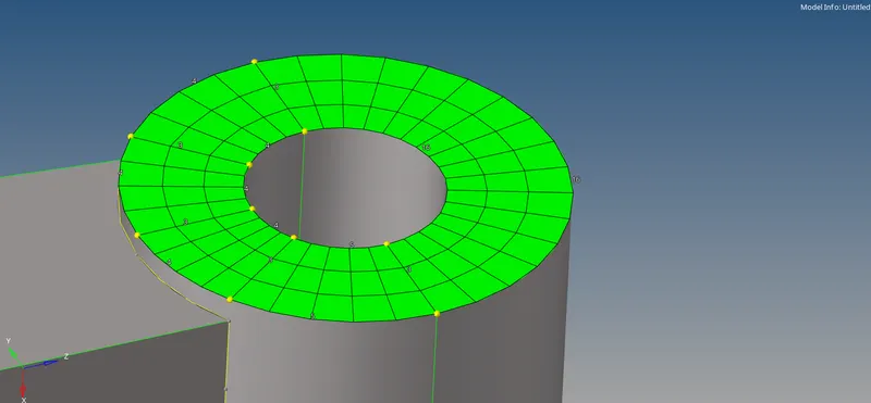
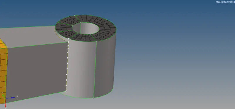
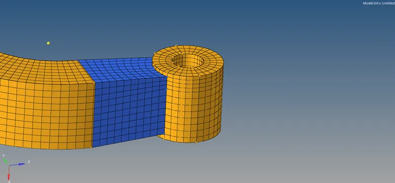
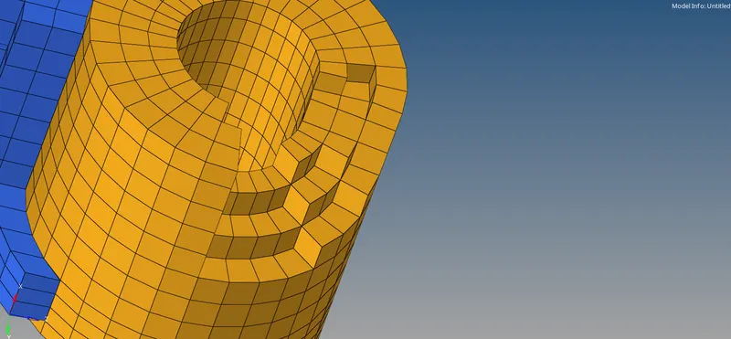
Once the hexa meshing is completed for all the components, the shell elements which were created during meshing need to be deleted. They are deleted by selecting the elements based on configuration.
RESULTS:
Completed model:
Component collectors:
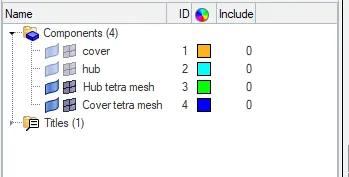
Completed model:
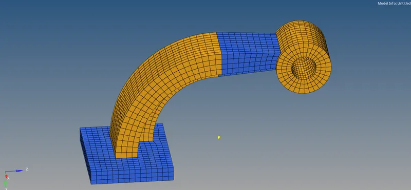
Component collectors:
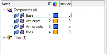
CONCLUSION:
The given engine file is edited as required and the respective calculations are performed. The tetra & hexa meshing is completed on the given models with all the elements passing the given quality criteria.