Implementing control logic using State-flow charts
AIM:
- To implement control logic of a “washing machine” using State-flow as per the given sequence.
- To make a Simulink chart for the “Gear shift” logic as per below conditions.
OBJECTIVE:
The objective of the project is to implement control logic using state-flow and create Simulink models using the state-flow.
MODEL SETUP:
Washing machine:
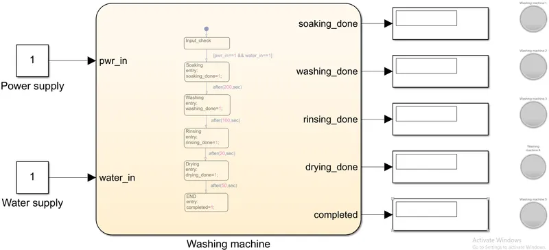
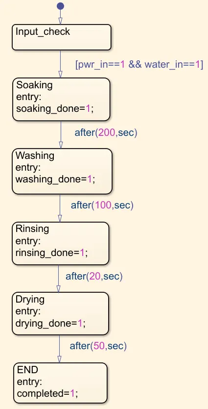
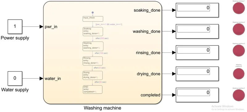
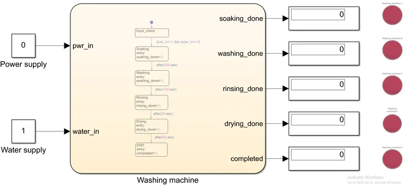
We have the chart block in the center within which we will define states and their related conditions. There will be inputs & outputs, for & from the chart block. The inputs are given with constant block, ramp block or any other block depending on the instance. We have the Power supply and Water supply as inputs for the chart block. Outputs from the chart block are viewed from the chart block with a display block, scope or any other block as required. When one state is completed, we have a LED to display that the state is completed and in case of no power supply or no water supply, the error is displayed. Within the chart block, we have the different states with defined conditions. If the conditions are satisfied, the state is executed. Once all the states are executed, the output is obtained. Here below, we have the various states in the chart block.
Gear shifting:
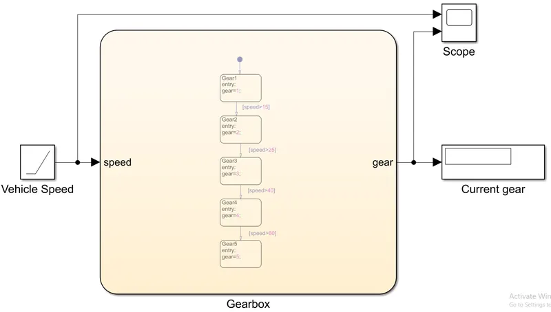
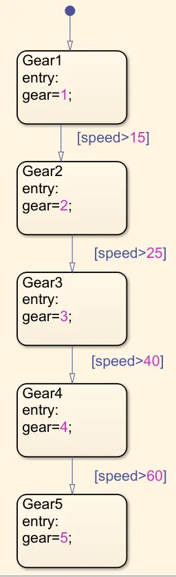
As in the previous case, the chart block is placed in the center. The inputs for the chart block are given from the left and the outputs obtained from the chart block are placed on the right. The vehicle speed is given as the input to the chart block and the gear number is obtained as the output from the chart block. To analyse the output, we have a scope block which shows the vehicle speed and the gear number. There is also a display block which displays the gear number. Here below, we have the various states in the chart block.
THEORY:
State-flow sequence for Washing machine:
- If the power supply is available, the system gets activated.
- If the Water supply is not available, stop the process & indicate through LED.
- Soaking time - 200seconds
- Washing time - 100seconds
- Rinsing time - 20seconds
- Drying time - 50seconds
- After all the processes have completed turn on the finished LED.
When the power supply is given, the system should get activated. With the water supply, the system should get started. If there is no power supply or water supply, the system should display error message. When the system has started working, the state Soaking should be carried out for 200 seconds. Followed by soaking, the state Washing should be carried out for 100 seconds. After this, the Rinsing state should be carried out for 20 seconds and after that the Dryer state should be carried out for 50 seconds. After all the processes have been completed, the Finished message should be displayed.
State-flow sequence for Gear shifting:
|
Speed Range (kmph) |
Gear |
|
0 to 15 |
1 |
|
16 to 25 |
2 |
|
26 to 40 |
3 |
|
41 to 60 |
4 |
|
Above 61 |
5 |
For speed range from 0 to 15, the First gear should be applied. As the speed increases from 15, the Second gear should be shifted. When the speed goes above 25, Third gear should be shifted. Above speed of 40 kmph, the Fourth gear should be shifted and above speed of 60, Fifth gear should be shifted.
EXPLANATION:
Washing machine:
The water supply and power supply are given as inputs to the washing machine. When the inputs are given, in the first state, the inputs are checked. If there is no water supply or power supply, further processes or states are not executed. The error is displayed. Once it is confirmed that there is water and power supply, the Soaking is executed. Soaking is done for 200 seconds. After 200 seconds have completed, the Washing is done. This is done with time-based condition. Washing is done for 100 seconds. After 100 seconds have passed, the Rinsing state is executed. It is done for 20 seconds. Once the rinsing is done, Drying state is executed. It is done for 50 seconds. Finally when all the processes are completed, the machine is ended. This is indicated by the LED when each of the processes are completed.
Gear changing:
The input is given by the ramp block in the form of vehicle speed. In the beginning, the first gear is kept as default. When the speed is increased from 0 kmph, first gear is kept. The first state is active. When speed goes beyond 15kmph, the gear is shifted to second gear. Then the seconds state becomes active. The speed is kept on increased. Above 25kmph, the third gear is shifted and the third state is activated. Similarly, the speed is kept on increased. When the speed is over 40 kmph, the gear is shifted. Then the state 4 becomes active. Again the speed is increased. When it goes above 60kmph, the fifth gear is shifted. After this the fifth state becomes active and it is active till the end of the simulation.
RESULTS:
Washing machine:
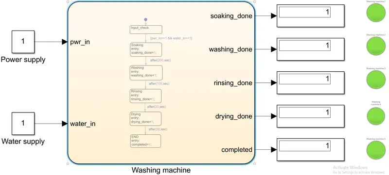
Here we can see that when there is both Power supply & Water supply, the system is run and all the processes are executed.
Gear changing:
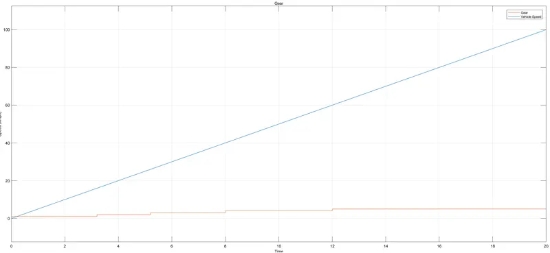
From the plot obtained in the Scope block, we see that the Speed curve starts from 0 in the y-axis and the Gear curve starts from 1 in the y-axis. When the speed has reached above 15kmph, the gear value has also increased by 1 point, meaning the gear is shifted up. Similarly, as the speed increases above 25kmph, the gear value has increased by 1 again. Conversely, we can also see that there is a gear shift at speeds above 40kmph and 60 kmph, meaning if the speed goes above the said value, the gear is shifted up. Note that above 5th gear, there are no gear shifts and the speed curve goes on increasing but the gear remains constant.
CONCLUSION:
Thus we have completed the simulation of Simulink models implementing the State flow for control logic.