3D tetra meshing of a turbocharger
AIM:
To perform 3D solid mesh on the given component with the given quality criteria.
OBJECTIVE:
The objective of the project is to learn to perform 3D solid meshing .
CAD MODEL:
The given model is a turbocharger component which is most commonly found in today's vehicles primarily cars.
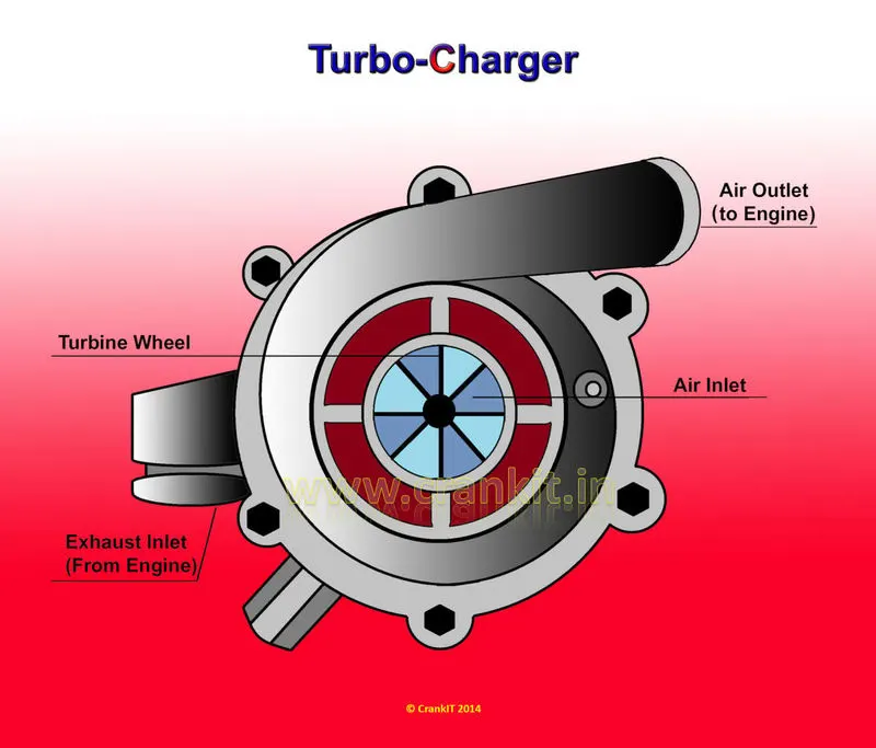
A turbocharger is a component present in the engine component of the car which works with the power of the exhaust gas coming from the engine and compresses air and feeds it to the engine. A turbocharger is made up of two main sections: the turbine and the compressor. It is the job of the turbine housing to guide the exhaust gas into the turbine wheel.
The compressor also consists of two parts: the compressor wheel and the compressor housing. The compressor’s mode of action is opposite that of the turbine. The compressor wheel is attached to the turbine by a forged steel shaft , and as the turbine turns the compressor wheel, the high-velocity spinning draws in air and compresses it.
PROCESS:
- Geometry cleanup
- Surface meshing with shell elements
- Generating solid mesh
- Checking for tet collapse failure
PROCEDURE:
Initially, the model is imported in the HyperMesh application using the Import model command.
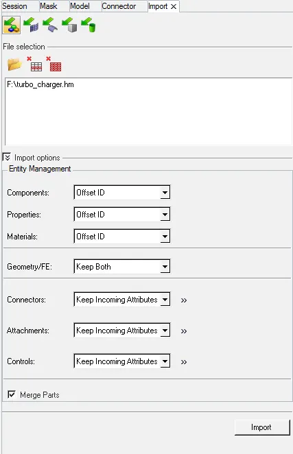
Once imported, the visualisation is changed to topo so that it will be easier to perform geometry cleanup. Solids, if found, are deleted.
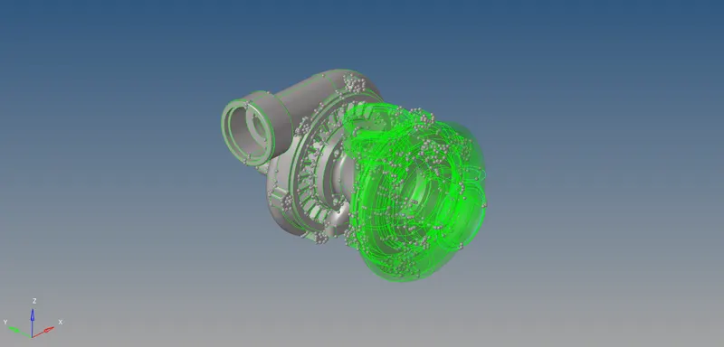
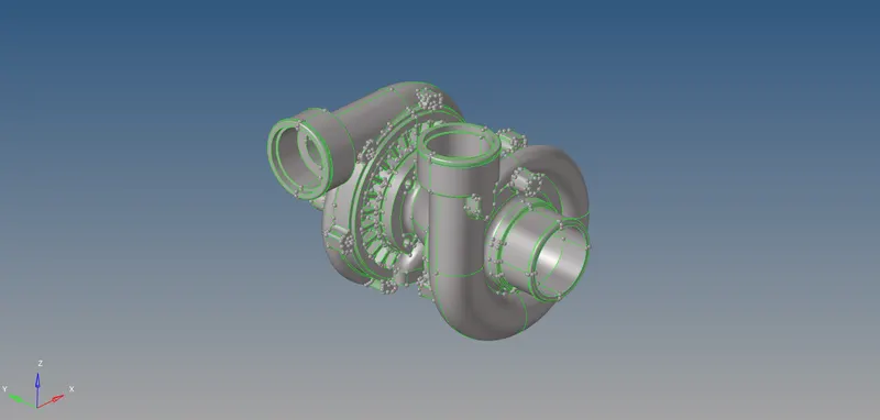
Free edges (red colour) & T-edges (yellow colour) are checked.
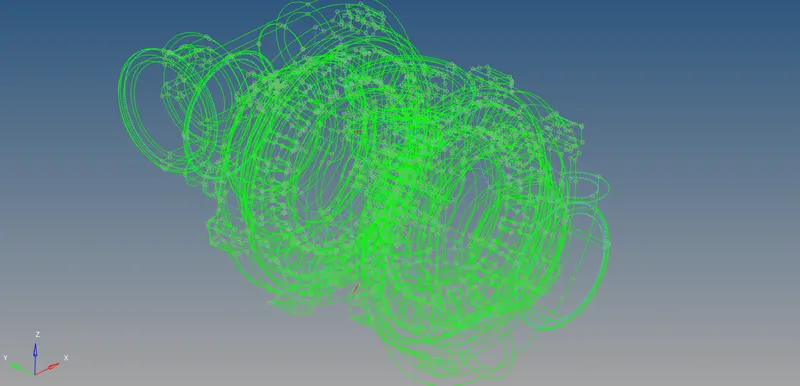
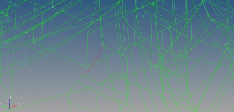
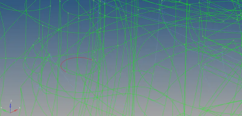
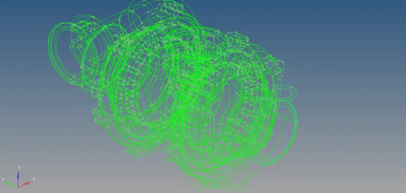
Once the geometry is clean, surface meshing is performed with shell elements.

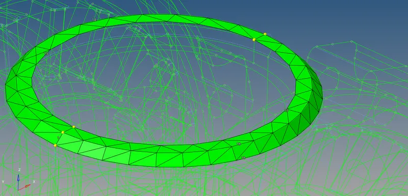
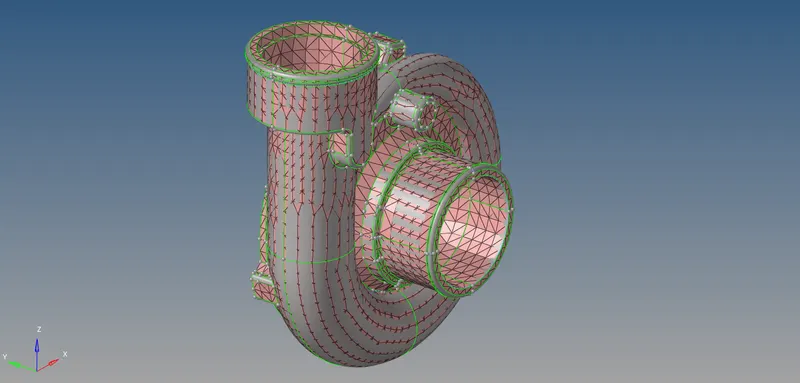
The surfaces are selected one by one and they are meshed with only tria elements.
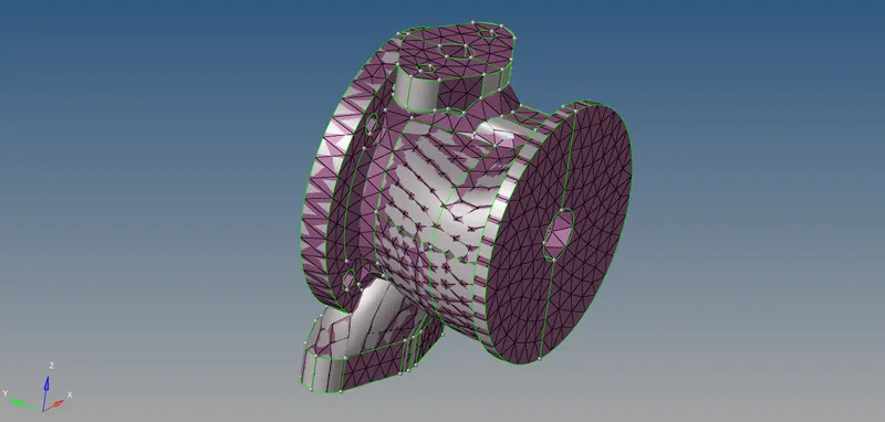
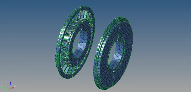
Each component is surface meshed with shell elements. Once surface meshing is completed, the solid mesh is generated from the shell mesh in the 3D panel tetra mesh option. Before that, the tetra mesh parameters are set so that the tetra mesh is generated in a streamlined manner.

Then all the shell elements are selected and the tetra mesh is generated from them.
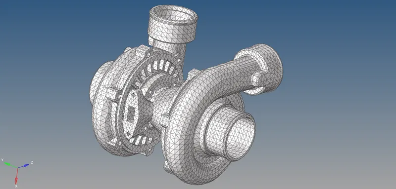
Once the tetra meshing is completed, we can mask some elements to verify that the tetra mesh is generated properly.
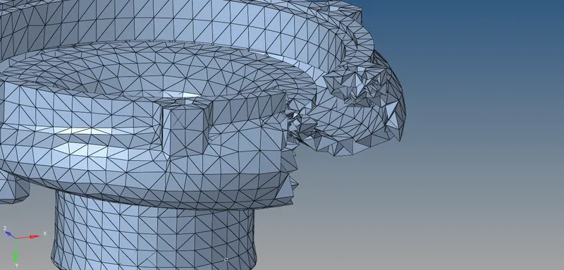
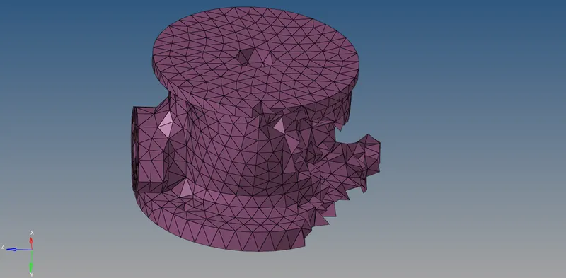
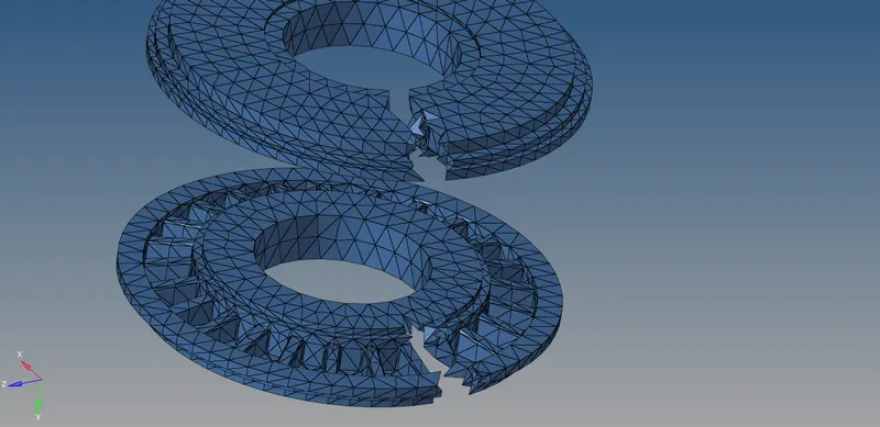
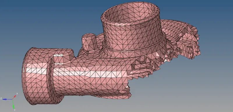
Next step, we check the tetra elements for tet collapse quality. In the check elements command (F10) 3D option, the target tet collapse value is entered.
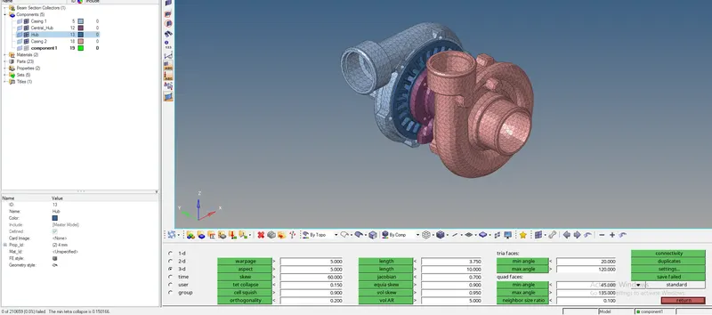
When checked, the failing elements are indicated in the status bar in the left corner.
RESULTS:
After completing the meshing procedure, we have the meshed FE model obtained.
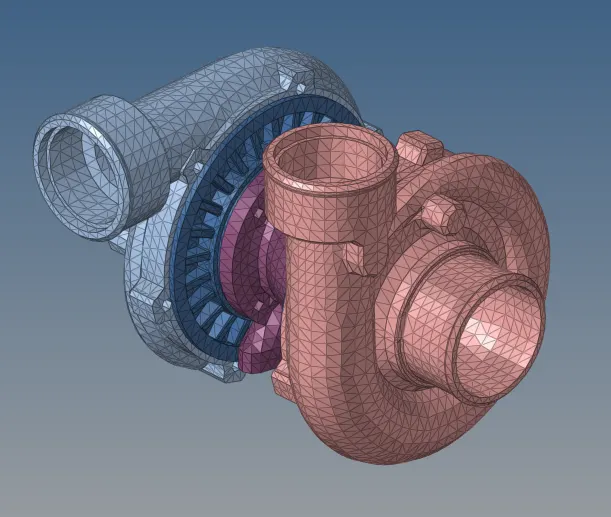
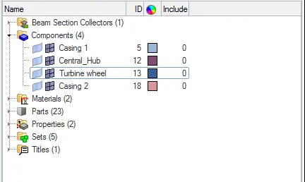
Component collectors:
LEARNING OUTCOMES:
The following are the learning outcomes of this project:
- Solid meshing is to be performed when the thickness of the component is more than 6mm.
- Before solid meshing, shell meshing needs to be performed on the surfaces with tria elements.
- Setting up the tetra mesh parameters before generating tetra mesh enables the tetra elements to be generated in a streamlined manner.
- Tetra re-meshing is recommended when there are many elements failing for tet collapse.
CONCLUSION:
From the above project, we have learnt tetra meshing, its needs and methods and also the ways to clear elements for tet collapse.