Shell meshing & deploying connections on door inner panel in Hypermesh
AIM:
To mesh the given component with the given quality criteria and assign thickness.
OBJECTIVE:
The objective of the project is to learn to mid-surface plastic components, mesh the mid-surface and assign thickness.
CAD MODEL:
The given model is an Inner panel of the side door in a passenger car.
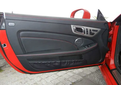
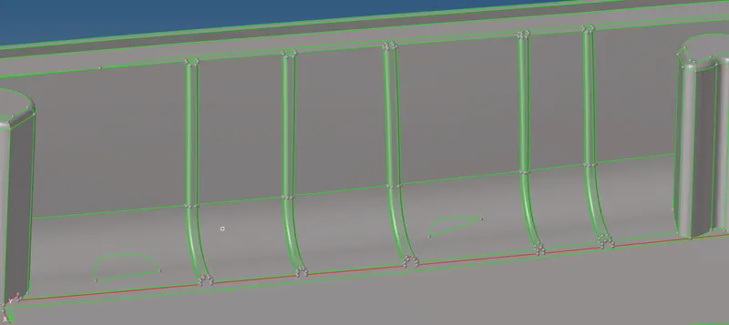
As we know, door panels are plastic components. They have varying thickness. There will be surface ribs which will be used for increasing structural strength.
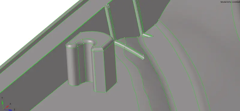
We also have features such as a locators (commonly called doghouse) which need to be modelled as a cross.
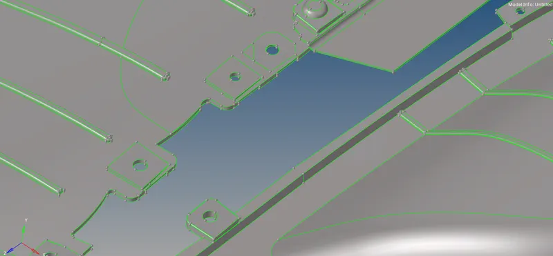
We can also see that there are some holes in the model which if captured properly can be used to give appropriate connections.
PROCESS:
- Geometry cleanup
- Extract mid-surface
- De-featuring & re-arranging of construction lines
- Meshing
- Resolving quality issues
- Assign property & material cards (and thickness)
- Performing mandatory checks
PROCEDURE:
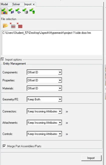
Initially, the model is imported in the HyperMesh application using the Import model command.
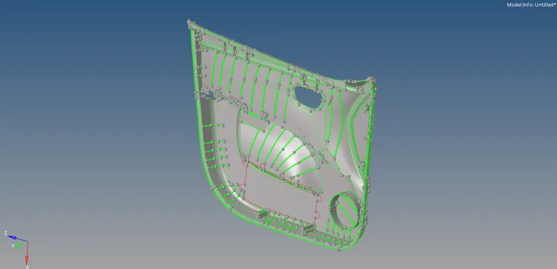
Once imported, the visualisation is changed to topo so that it will be easier to perform geometry cleanup.
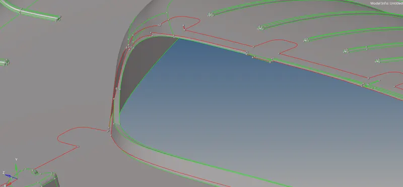
In the topo mode, the model is thoroughly studied for any surface deformities or missing surfaces. We can find that there is a surface missing due to which there is a free edge. But since there is another surface, we can use that surface to extract mid-surface.
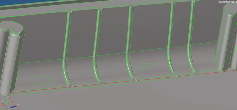
Here we see that there are two edges inside the surface. But since they are of no particular use, we can toggle them.
Then, we go right away with the mid-surface extraction. Before that, we can see fillets with very less length. These fillets, if captured exactly, will fail for minimum element length. So, we de-feature the fillets falling below the minimum element length using the defeature command.
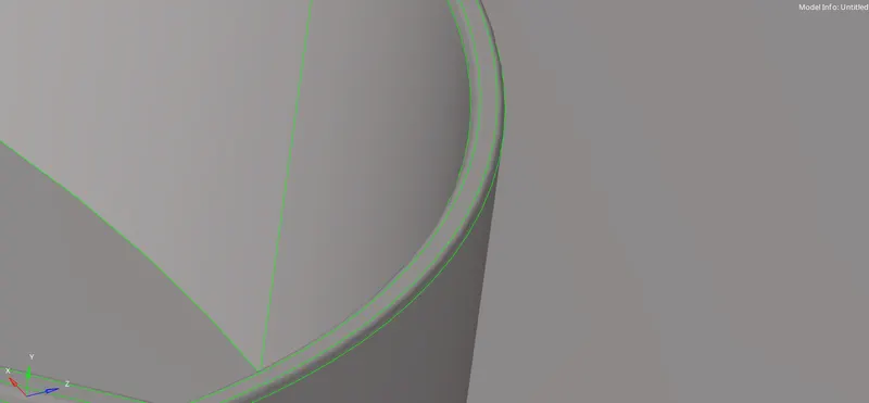
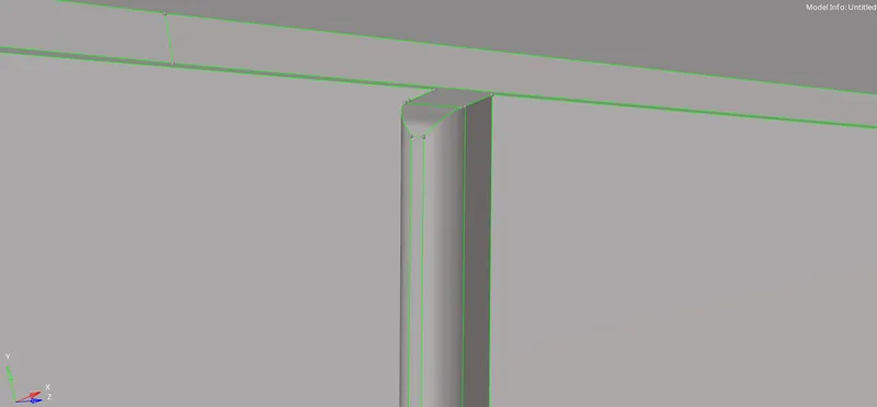
We select the fillet surfaces and defeature them. Fillets are majorly present in ribs.
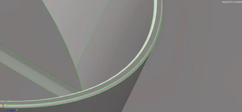
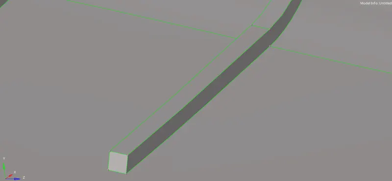
First, the mid-surface of the base surfaces is taken. Then the mid-surface for ribs & other features are taken and connected with the base surface. The thickness of the base surface is measured using the distance command. The thickness is measured at various places.
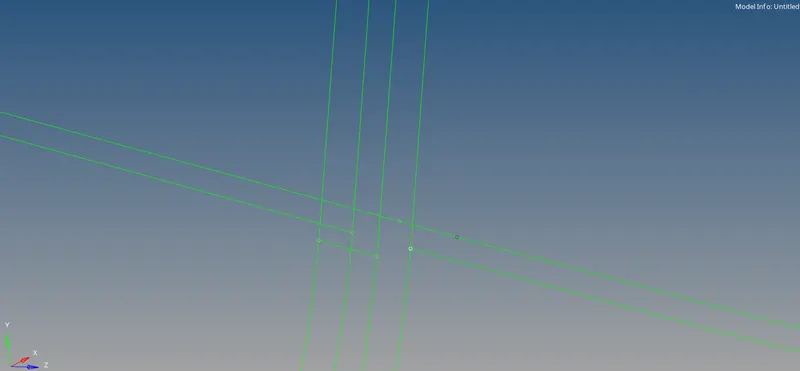

The mid-surface can be extracted by offset of one surface to half of the thickness. This is done in the surface edit command with the offset option.

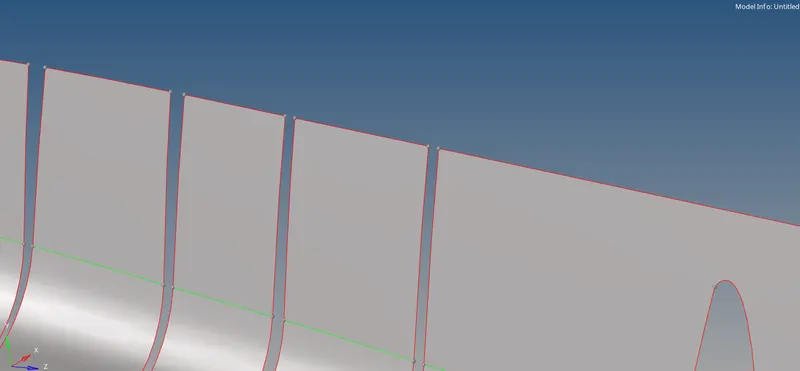
Another method is using the final edit tools in the midsurface command, we can generate a middle surface between the two surfaces.

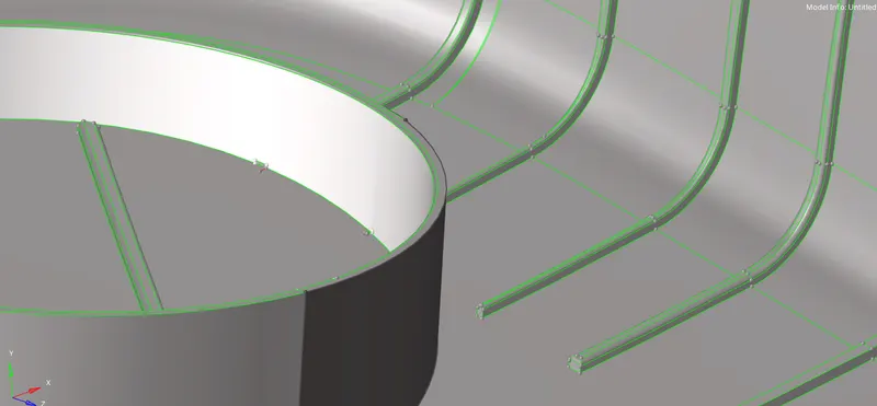
Using the two methods, mid-surface is extracted for the base surfaces. For ribs, a middle line is generated in the top & bottom of the rib.
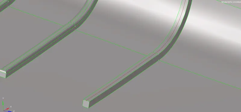
Then a new surface is created with the two lines. The offset method can also be used for taking mid-surface of the ribs.
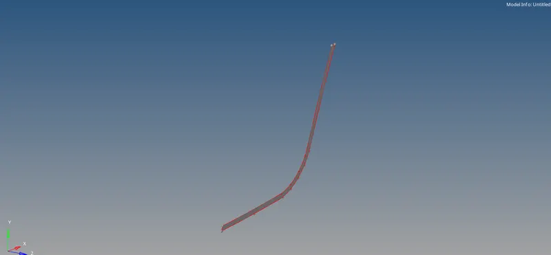
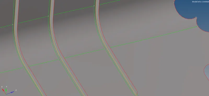
Once the mid-surface is extracted for the ribs, they need to be joined with the base surface so that there will be a connectivity between all the surfaces. For this, the extend option is used in the surface edit command.

Using this option, the ribs are extended and connected with the base surface.
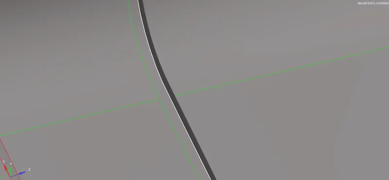
For the doghouse, we will be creating a cross surface similar to the parent geometry.
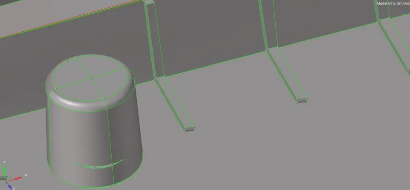
To create a cross surface, the edges of the parent geometry are selected and lines are created with them.
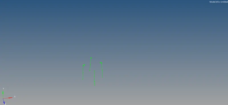
Then, the cross surface is created and then extended to the base surface.
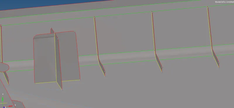
Once the mid-surface is completely extracted, construction lines are re-arranged by toggling lines and splitting the surface with lines.
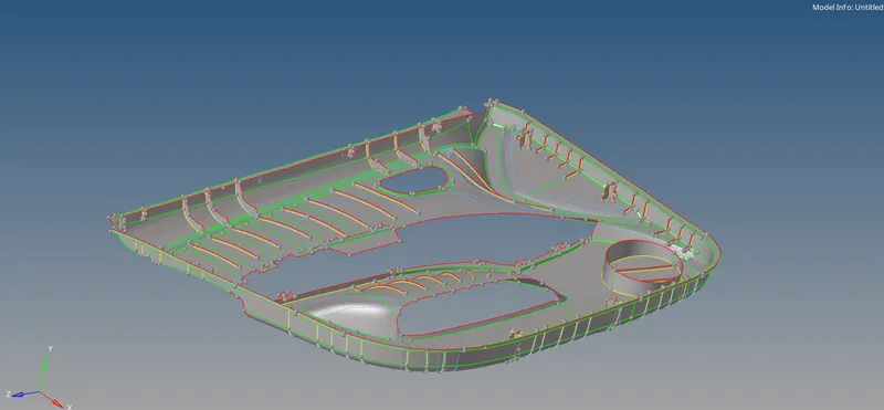
Fillets and construction lines falling below the minimum element length are toggled.
After the construction lines are re-arranged, the quality criteria is set. The target element length is 4 with the minimum & maximum element lengths as 2 and 8. Other quality criteria are as below.
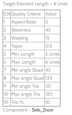
The quality criteria is set in the Criteria file settings under the Preferences tab.
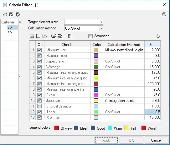
Next, the meshing is started. First the features are meshed and then the base surface is meshed. Meshing is done in the automesh command in the 2D panel.

Large surfaces are split into smaller surfaces of box shape to get better mesh flow & control over the number of nodes.
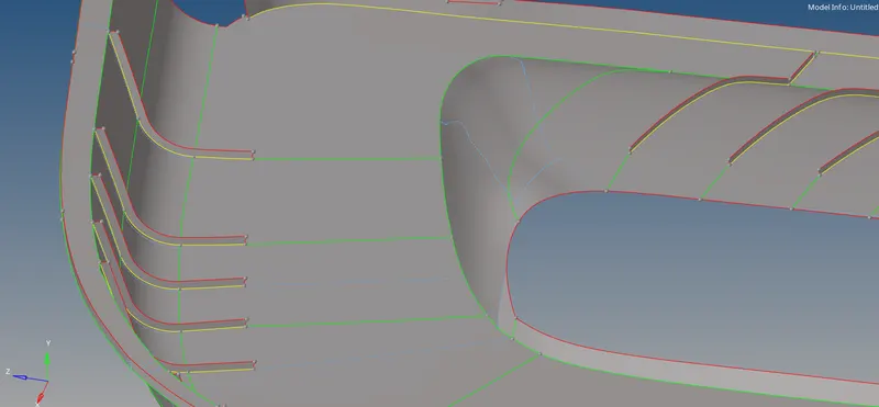
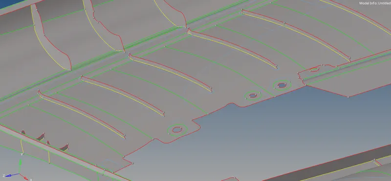
The fixing of failing elements for quality can be done simultaneously as meshing is being done on surface by surface or can be done after all the surfaces are meshed. Surfaces can be re-meshed using the automesh command by selecting elements.
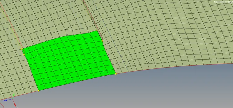
The rebuild command helps to reconstruct the existing mesh. It tries to give a better mesh than the existing mesh flow.
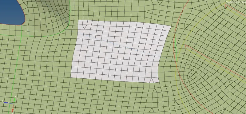
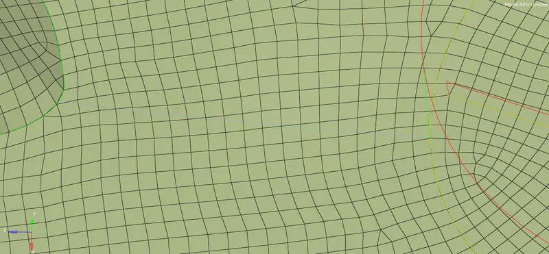
The quality index cleanup tools are used to split the quad elements, drag tria element and optimize elements.

Two adjacent tria elements are combined using the combine tria tool and the swap edge tool is used to swap tria elements.
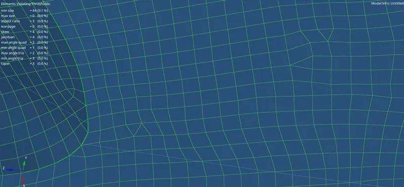
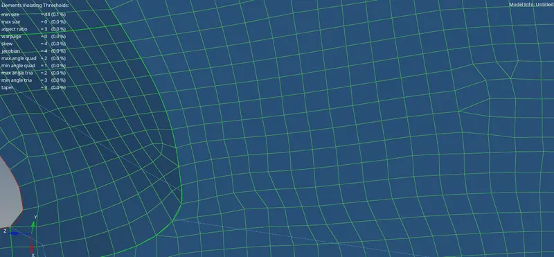
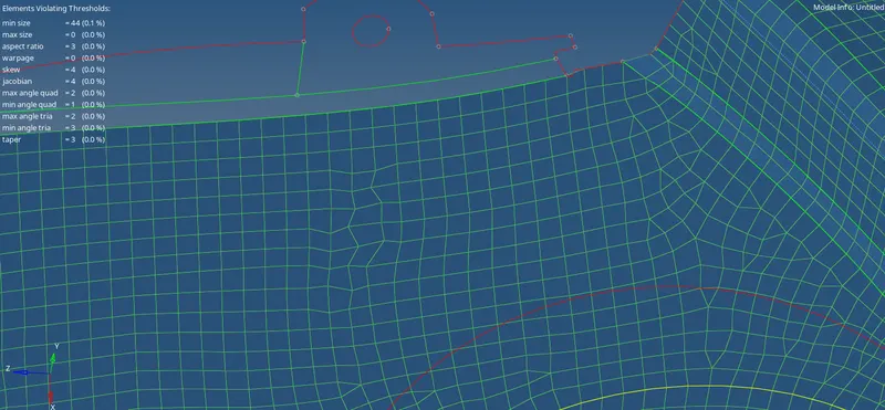
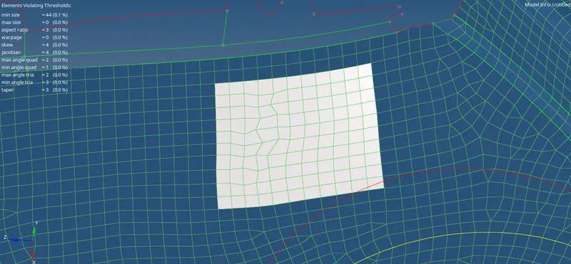
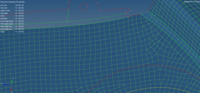
When there is a distorted mesh flow, the mesh flow is cleared using the smooth command. The smooth command inside the quality index command can be used or the smooth command can be used.
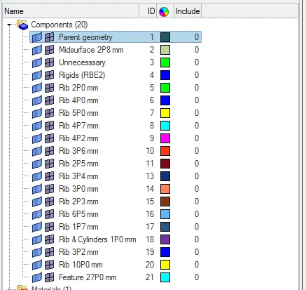
Finally, after the meshing and clearing of the quality issues is completed, the thicknesses are assigned to all the FE elements according to their thickness in the parent geometry. A new component collector is created and the FE elements are organized to that collector.
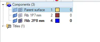
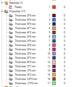
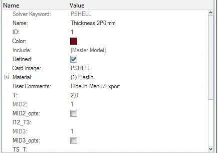
The material & property cards are created with the relevant properties.
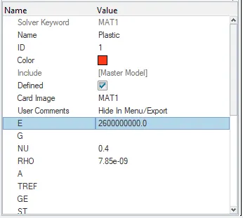
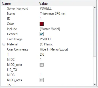
Then they are assigned to the component collector.
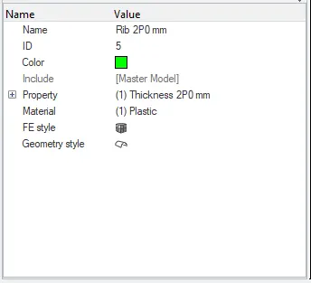
After thicknesses are assigned, the mandatory checks are performed. First the edges are checked. All the elements are selected and the edges are checked. To view the edges, the mesh visualisation is changed to component mode.
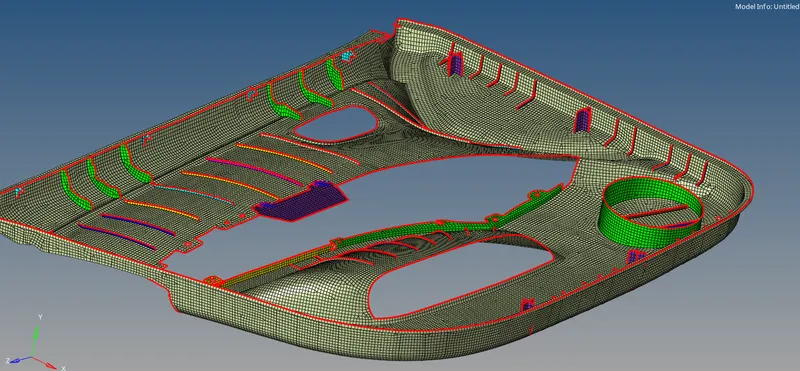
This check is performed for free edges and T-edges. It is mandatory to have free edges only around the holes and around the component.
Then the normals are checked for the component. All the elements are selected and the colour normals or vector normals are viewed.
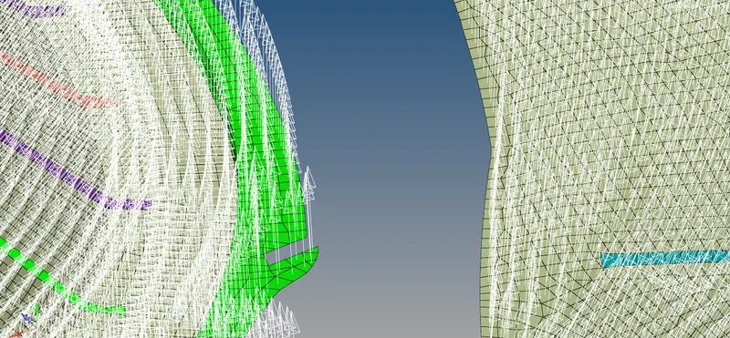
For colour normals, all the elements should have red colour on one side and blue on the other side. In case of vector normals, all the normals should be in the same direction.
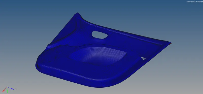
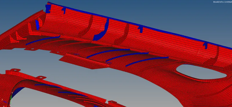
If the normals are reversed for few elements, they are corrected. Next, the dependency check is performed on 1D elements. Since we do not have 1D elements, this check need not be performed. After that, the penetration check is performed.

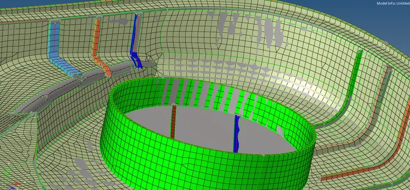
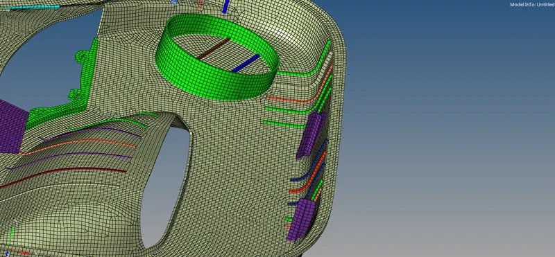
Finally, to see if the FE model represents the original CAD model, the 2D elements traditional representation is changed to 2D detailed element representation.
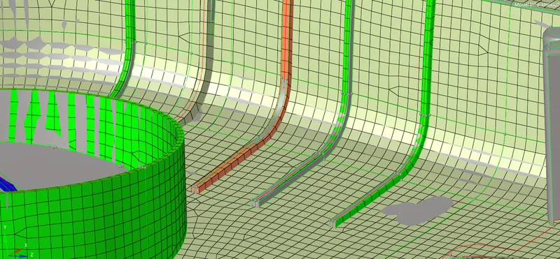
Thumb rules followed while meshing:
- Back to back trias.
- No tria elements at the edges or hole edges of the component.
- No opposite trias.
- Capture fillets with same rows of quad elements.
- No rotating quads.
- Trias, if present, maintained in one direction.
RESULTS:
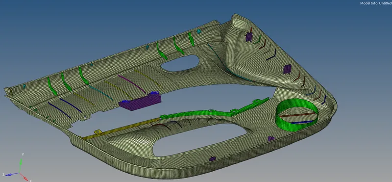
After completing the meshing procedure, we have the meshed FE model is obtained.
Complete mid-surface:
Completed model:
Component collectors:
Material & property cards:
2D detailed element representation:
LEARNING OUTCOMES:
The following are the learning outcomes of this project:
- The method of mid-surface extraction for plastic components is learnt.
- Mid-surface representation for doghouse.
- Re-arranging of construction lines for maximum feature capturing.
- Meshing without rotating quads, opposite & back to back trias.
- Creating & assigning material & property cards.
- Thumb rules for shell meshing.
- Mandatory checks to be performed after meshing & their necessity.
CONCLUSION:
Thus the side door inner panel model is mid-surfaced & meshed according to the given quality criteria in Hypermesh.