Shell Meshing of Instrument panel substrate
AIM:
To check for geometrical errors in the given CAD model and mesh the model with the given quality criteria.
OBJECTIVE:
The objective of the project is to mesh plastic components and obtain a mesh with minimal element failure and maximum feature capturing.
PROCESS:
- Perform geometry clean up and resolve geometry errors.
- Extract the mid-surface of the component.
- Assign property IDs for the mid-surface and assign quality criteria for meshing.
- De-feature fillets and construction lines violating quality criteria.
- Mesh the component and resolve quality issues.
- Assign thickness to the mid-surface.
SOFTWARE USED:
ANSA (Automatic Net generation for Structural Analysis) v19.0.1 64-bit
MODEL:
An Instrument panel / dashboard is a very familiar component in cars. It is basically a control panel located in front of the driver which contains & shows various controls & information. It also contains air-conditioning vents and glove box for minimal storage in the front.

A Dashboard in a car
The given CAD model is an instrument panel which is a plastic component meaning it has variable thickness.
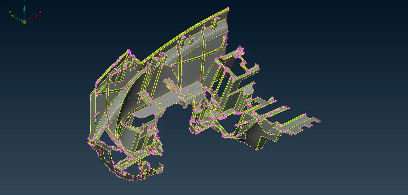
Given CAD model
Before the geometry clean-up is done, the surfaces of the CAD model need to be stitched with each other. This is done using the FACES -> TOPO command in the Topo module.
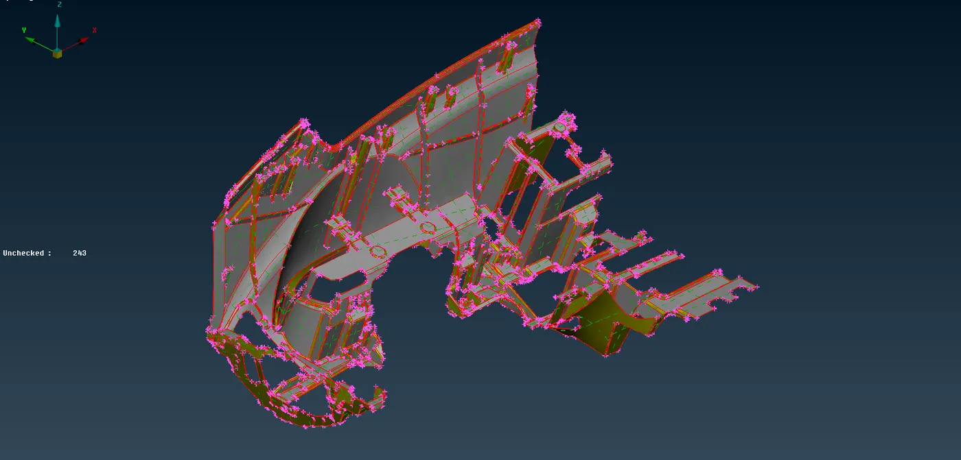
CAD model before doing Topo command
CAD model after doing Topo command
Next, the Geometry checks are done. This can be seen in the TOOLS tab under CHECKS -> GEOMETRY.
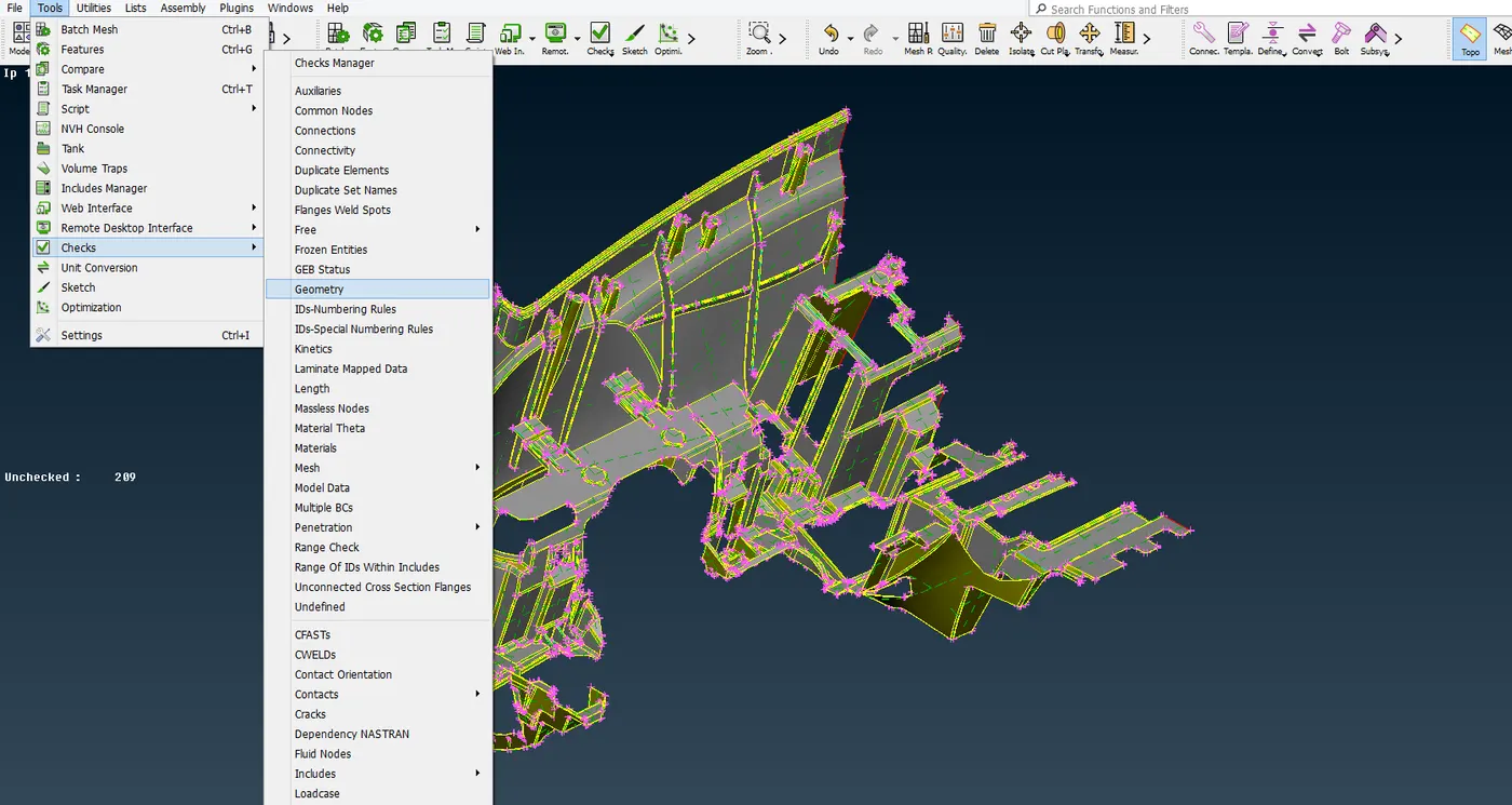
The Geometry clean up can also be done through the CHECKS command.
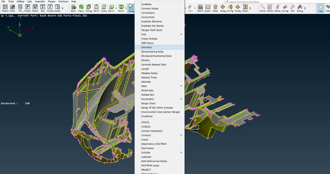
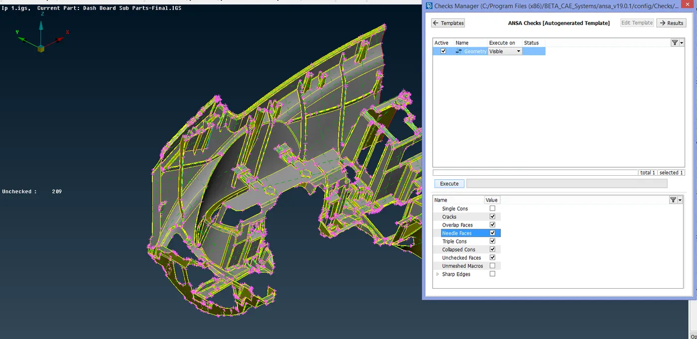
Performing geometry checks
Upon executing, the errors or geometrical issues in the model will pop up.
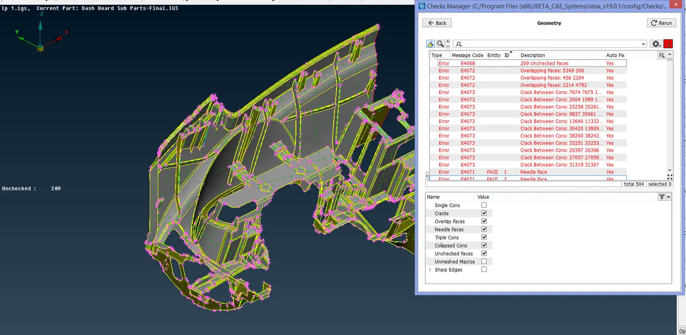
Geometry / Topological errors in the model
These errors can be fixed manually one by one or can be fixed automatically. When fixing automatically, the errors are fixed by ANSA.
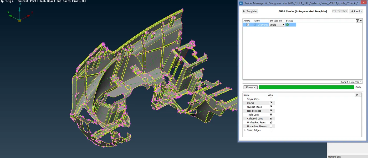
CAD model after the Geometry erros are fixed
Once the errors are fixed, the geometry checks should be run again. It should be ensured that there are no geometry issues.
MIDSURFACE EXTRACTION:
Before the mid-surface for the component is extracted, the thickness of the surfaces is to be measured. The thickness of the surfaces is measured using the MEASURE command under the UTILITIES tab.
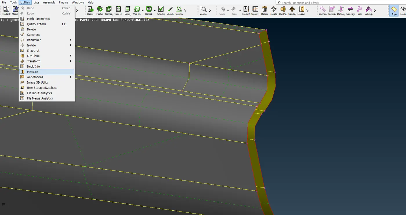
The MEASURE command
The distance between 2 cons can be measured with the CONS/Curves option.
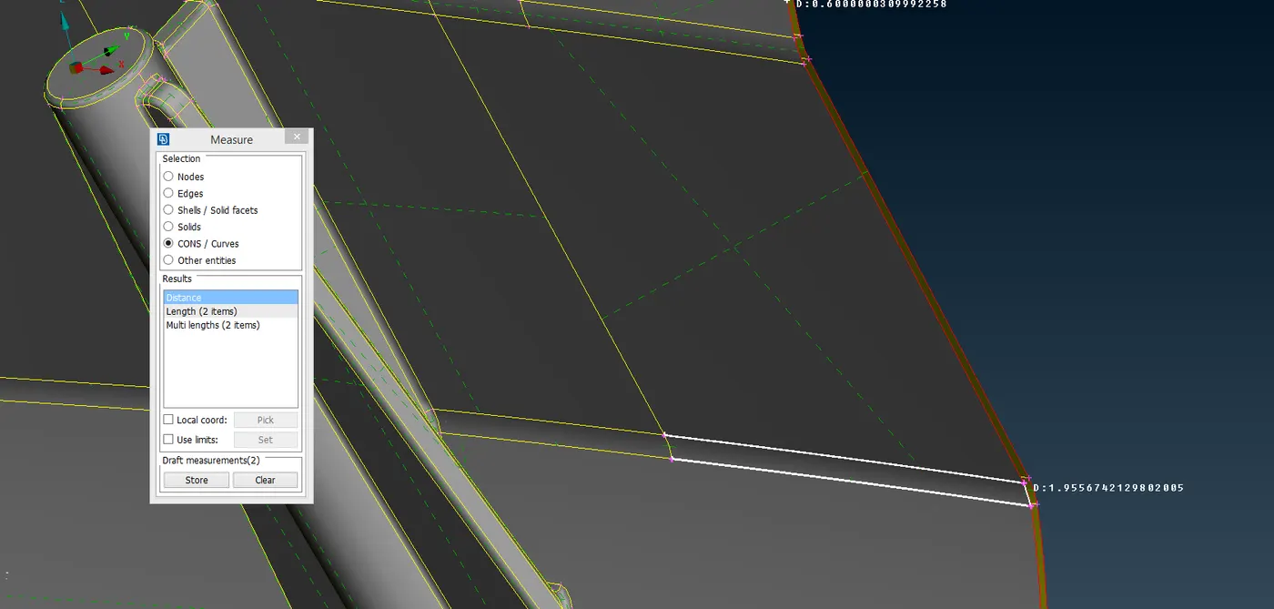
Measuring the distance between two CONS
Similarly, the distance between 2 nodes is measured with the Nodes option.
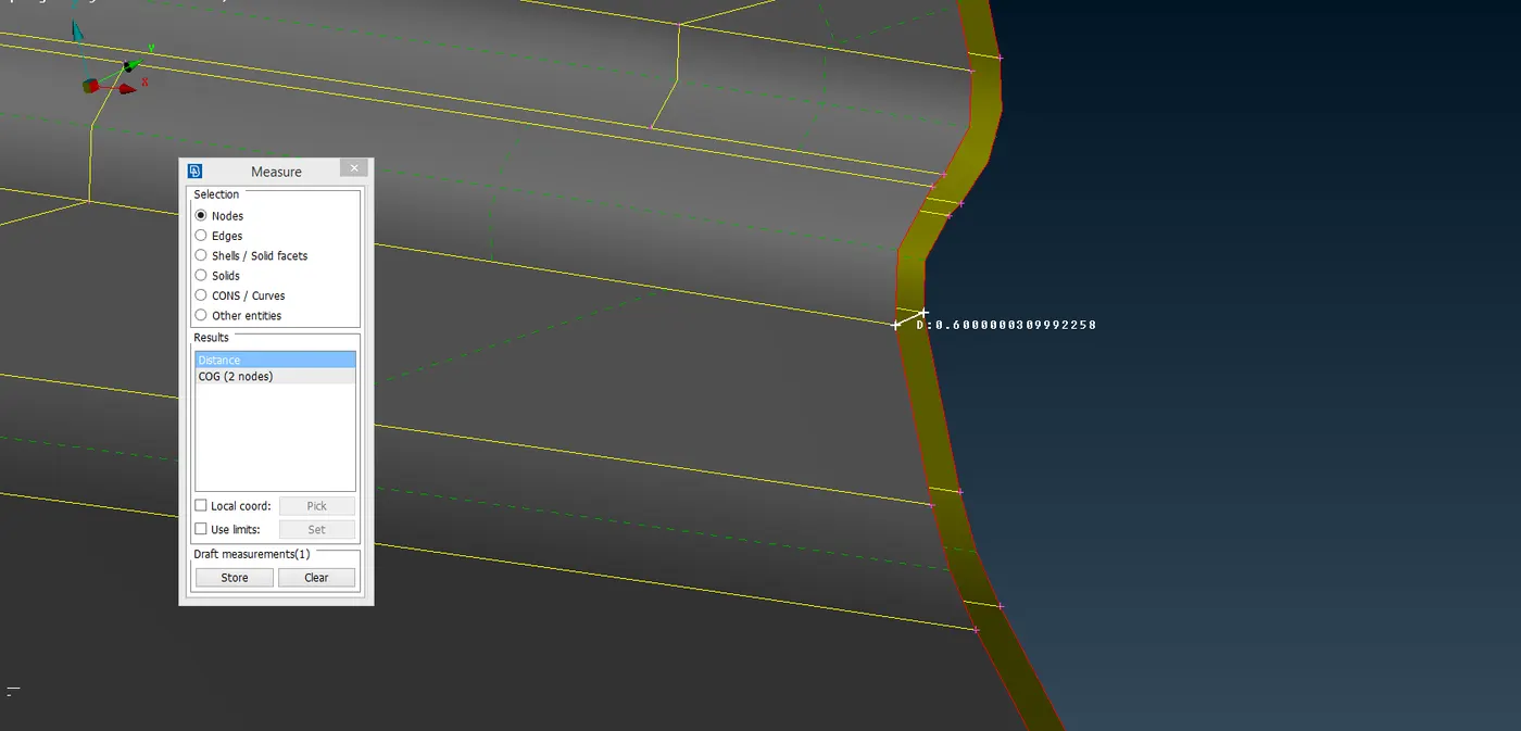
Measuring the distance between two nodes
Mid-surface extraction is majorly done using the FACES -> OFFSET command in the Topo module.
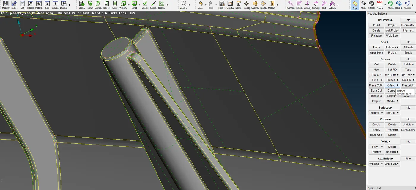
The OFFSET command
Since the thickness of the surface is 0.6mm, the surface is offset to half of the thickness value to obtain the mid-surface.
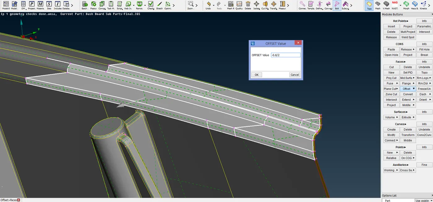
Offset the faces using OFFSET command

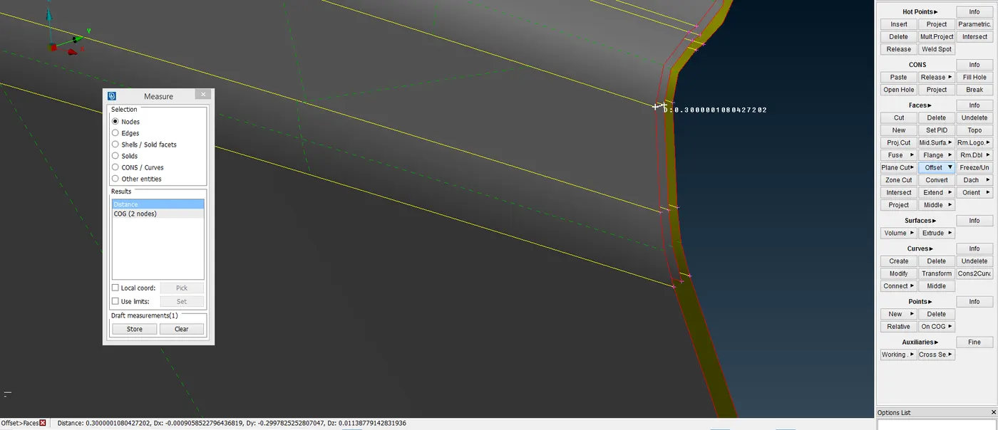
It can be seen that the mid-surface is generated exactly to half of the thickness value of the surface.
This way, the mid-surface is generated for other surfaces.
At complex geometries where the thickness cannot be measured using cons or nodes, Weld spots are used. These spots are created on the surface and then projected to the other surface. Then the distance between the two weld spots is measured and the value so obtained is taken as the thickness of the surface.
Weld spots command can be found under the HOT POINTS -> WELD SPOTS.
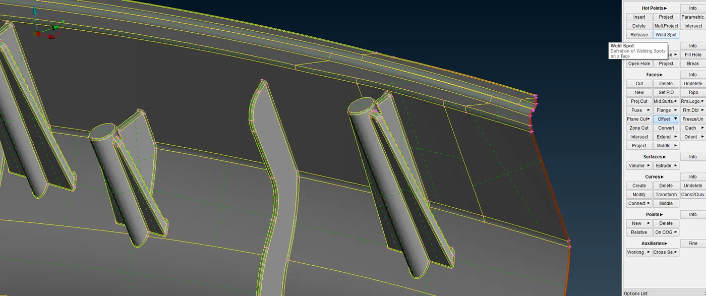
Creating WELD SPOTS
Weld spots can be created by clicking on any surface.
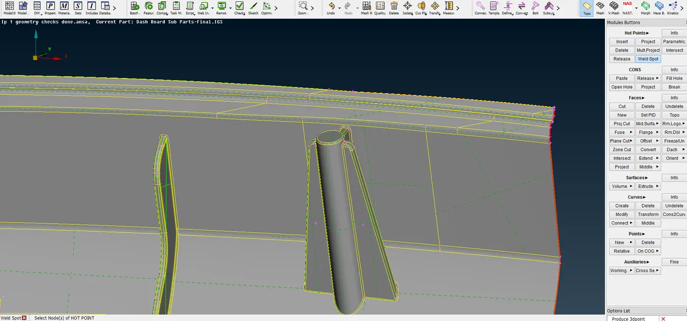
The weld spots are projected to the bottom surface using the HOT POINTS -> PROJECT.
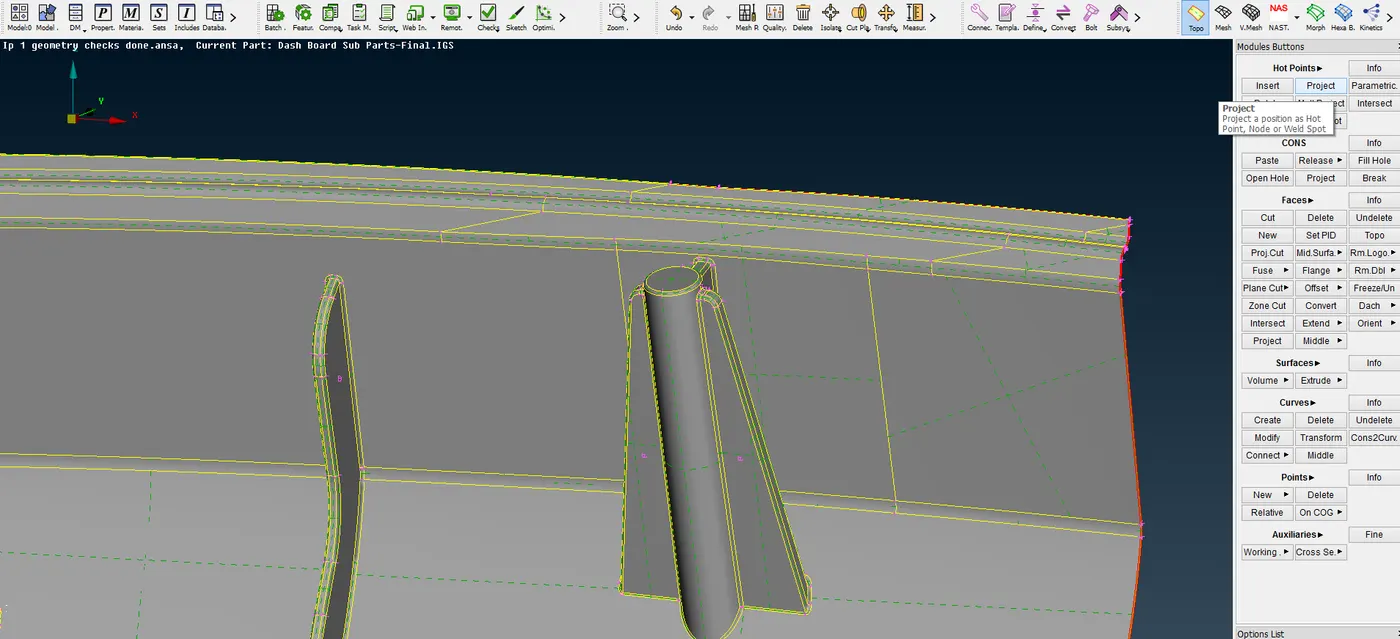
The PROJECT command
After selecting the command, the weld spot is selected and then the surface, to which the weld spot needs to be projected, is selected.
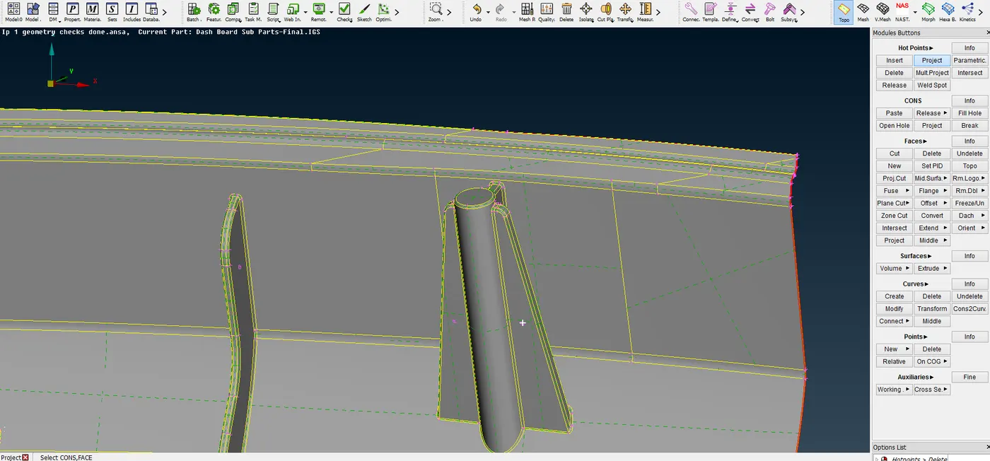
PROJECTING weld spots
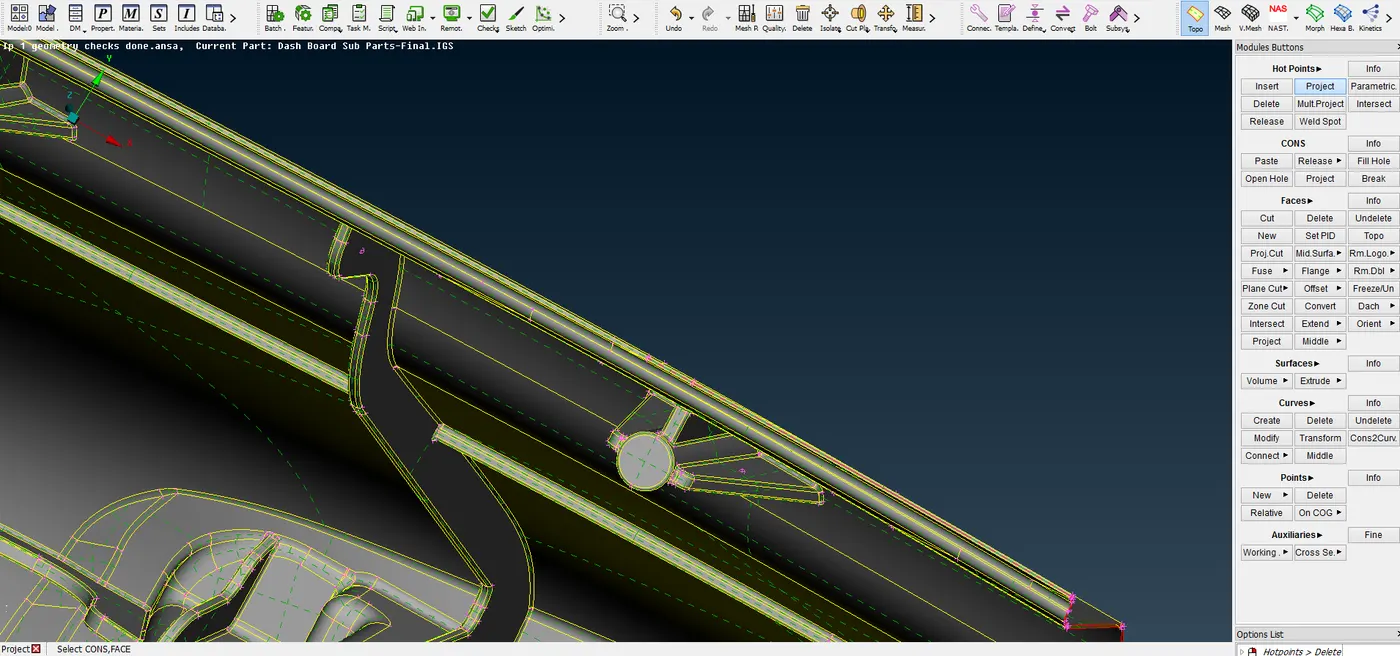
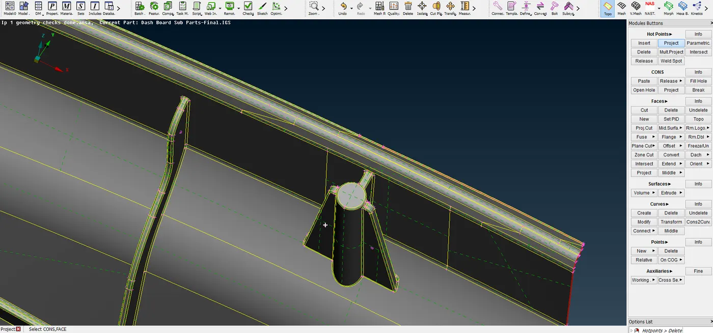
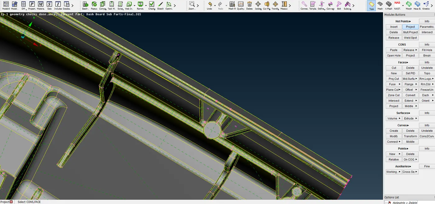
Then the distance between the 2 weld spots is measured and the thickness value is obtained.
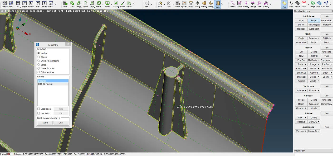
Measuring the distance between the weld spots
The mid-surface can also be extracted using the FACES -> MIDDLE command. This command basically generates a middle surface between the two selected surfaces.
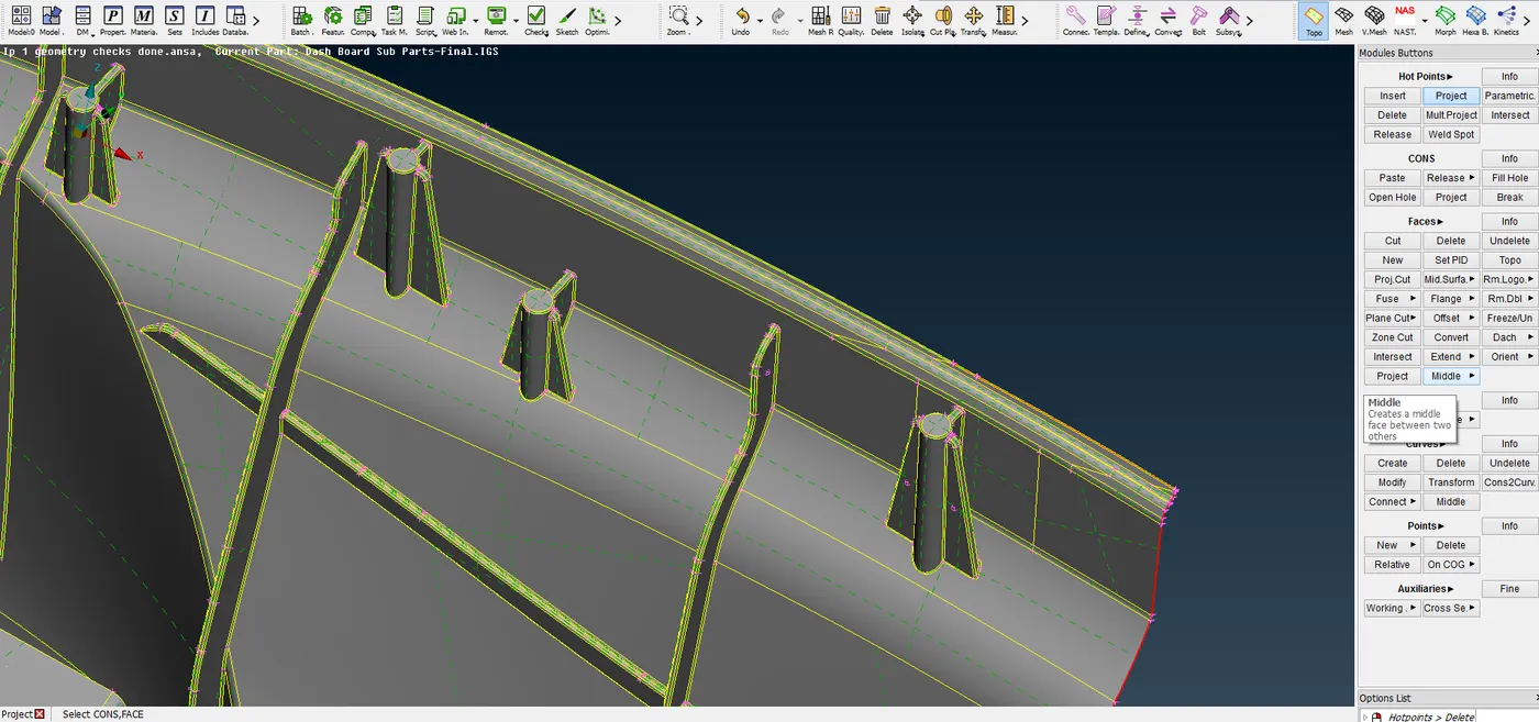
The FACES -> MIDDLE command
The first surface is selected.
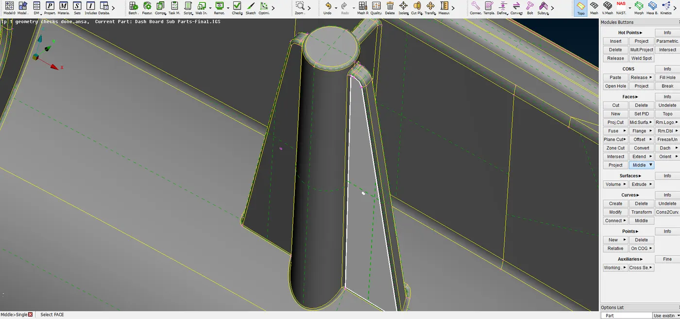
Then the second surface is selected. After the second surface is selected, the confirmation to accept the surface pops up.
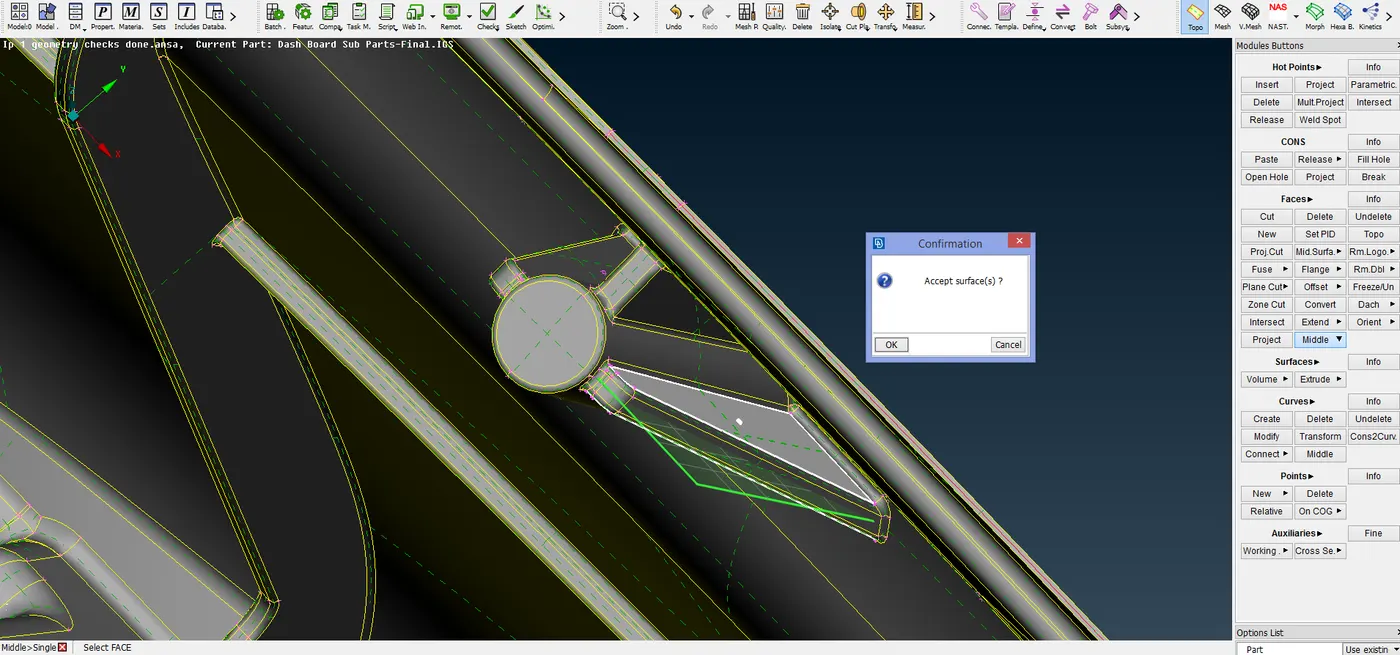
Upon accepting, the middle face (mid-surface) is created.
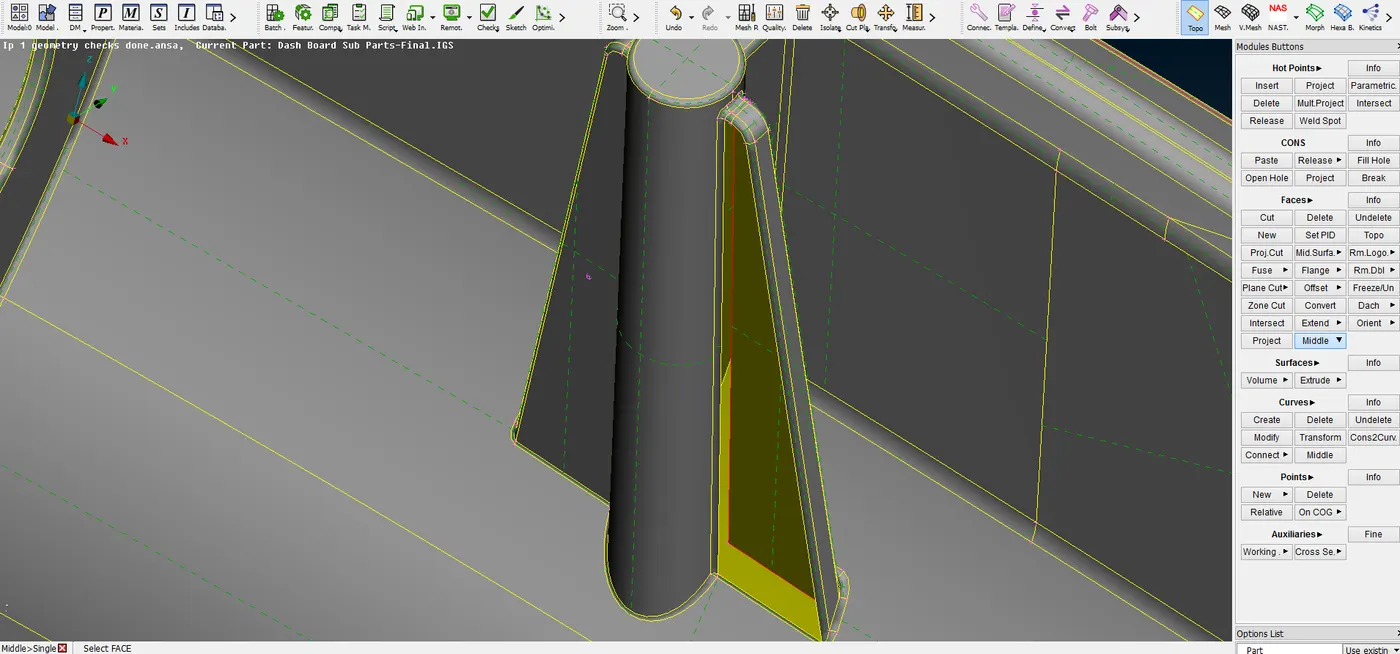
These two methods are used to extract the mid-surface for the whole CAD model.
Once the mid-surface for the whole CAD model is extracted, some of the surfaces need to be extended to the base mid-surface to replicate the same as in the parent surface. These surfaces are extended using the FACES -> EXTEND command.
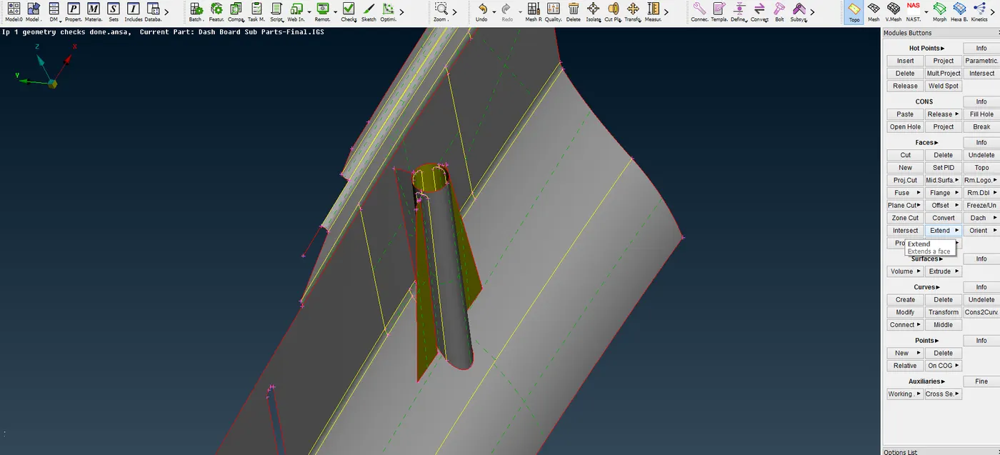
The EXTEND command
The extend command is done by selecting the single cons (red colour).
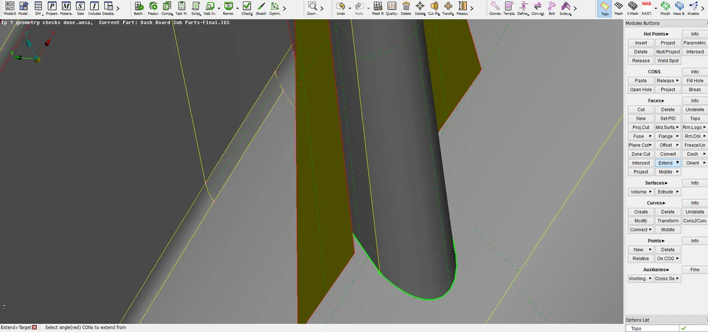
Upon accepting, the face up to which the surfaces need to be extended is selected. Once the face is selected, upon accepting the surface is extended. As there are 3 surfaces intersecting, there will be a triple con (cyan colour) created at the intersecting surface.
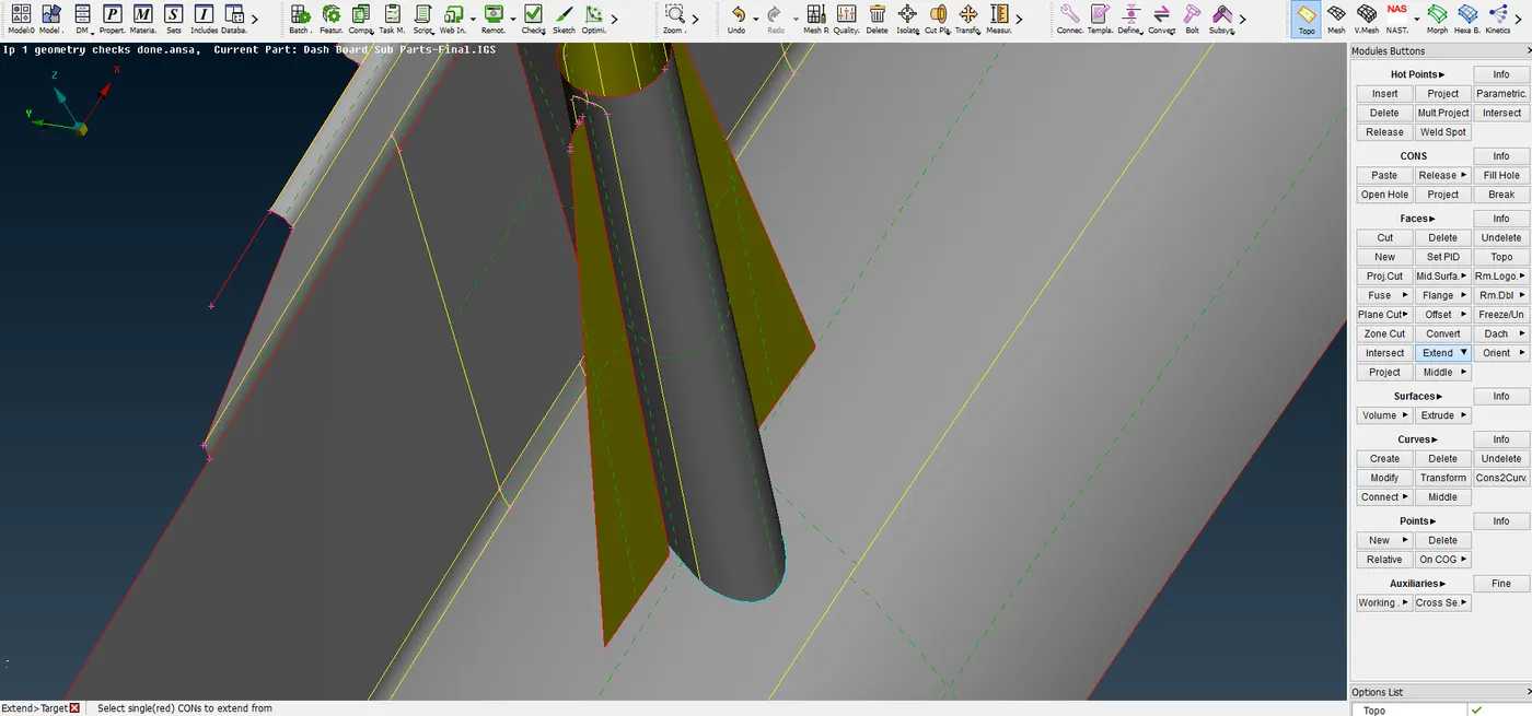
This way, the ribs are extended to the base mid-surface.
Then, in the top we can see a hole opening. These types of holes are closed using the FILL HOLE command. It is under the CONS command button in the Topo module.
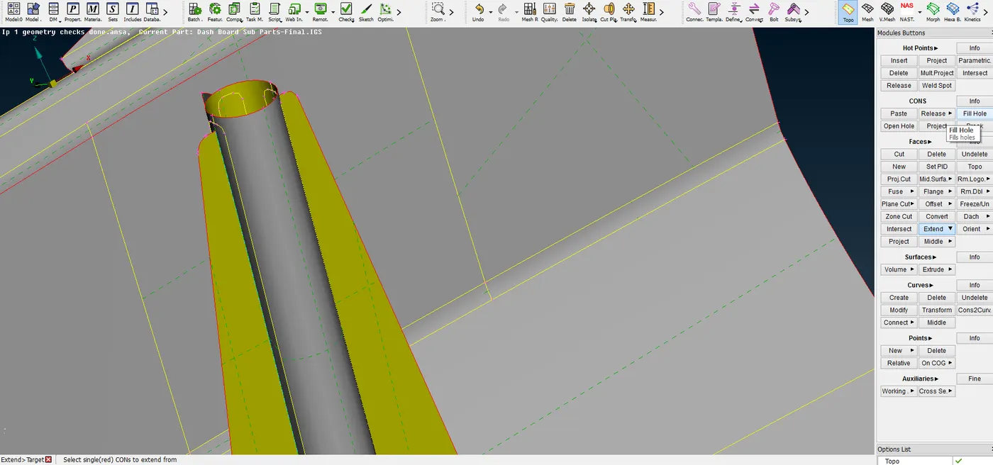
The FILL HOLE command
The hole which needs to be closed is selected.
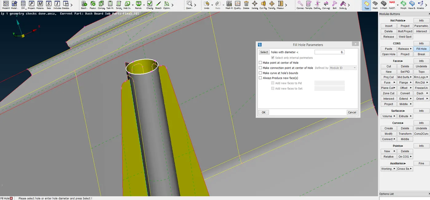
After accepting, the hole is closed by creating a surface automatically.
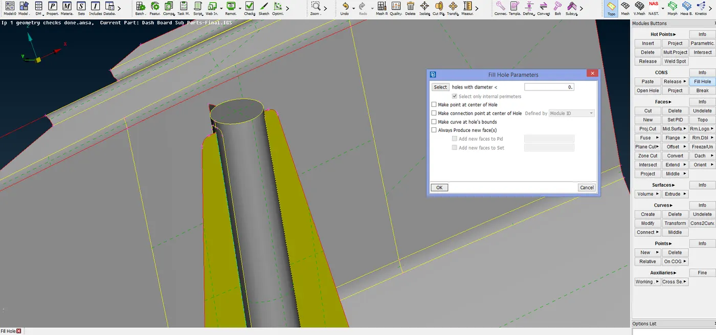
When there are many such holes to be closed, all the holes can be closed altogether at one stretch. In the Fill holes parameters dialog box, all holes within a specified diameter can be selected and new surfaces can be created to close the holes.
ASSIGNING PROPERTY ID (PID) & QUALITY CRITERIA:
The Property ID is set to each of the surfaces according to their thickness values. It is done using the SET PID command under the FACES module button in the Topo mode.
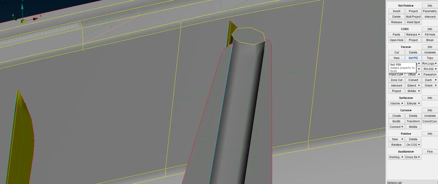
Setting the Property IDs
After clicking the command, the surface to which the Property ID is to be set is selected.
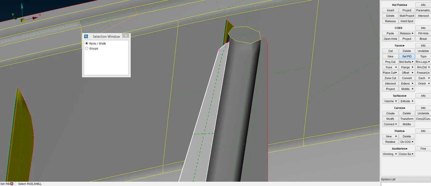
Then upon accepting, the Property help dialog box pops up. In that the property is selected.
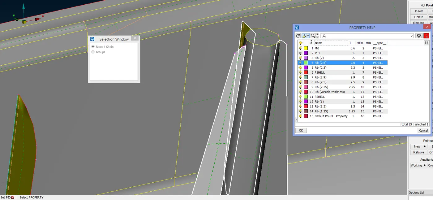
In case of setting a different Property ID, a new Property ID needs to be created using the NEW button. Under the NEW button, the PSHELL option is selected. For shell mesh or 2D meshing, the PSHELL option is selected. In case of solid mesh or 3D meshing, the PSOLID option is selected.
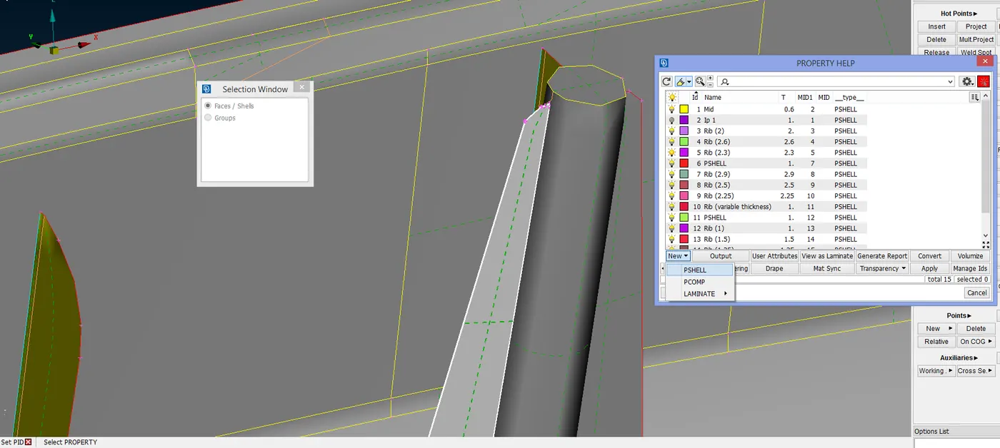
Creating a NEW Property ID
In the dialog box, the Property ID name and thickness value is given. After accepting, the Property ID is set to the particular surface.
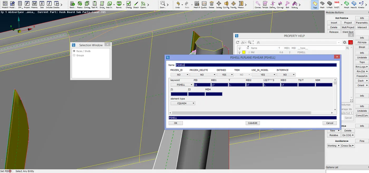
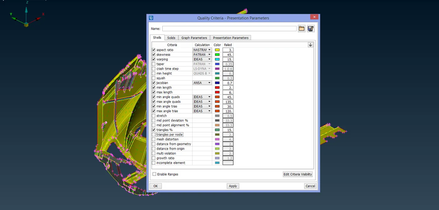
After the Property IDs are assigned, the Quality criteria for meshing needs to be set. This is the minimum quality standards which every FE element in the mesh needs to pass.
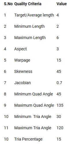
QUALITY CRITERIA
Before the quality criteria are set, the Mesh parameters are set. It is under the UTILITIES tab.
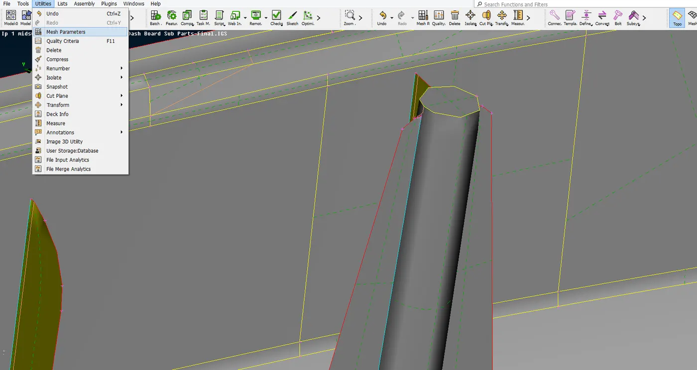
MESH PARAMETERS
In the BASIC tab, the Minimum & Maximum element length and Target element length are given.
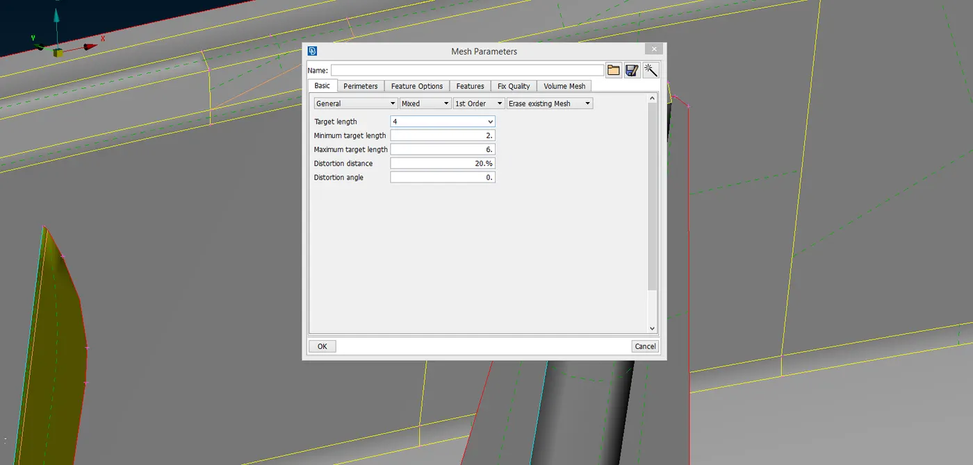
Then the Quality criteria are set. It is also under the UTILITIES tab. The F11 key is a shortcut to the Quality criteria, which can also be used.
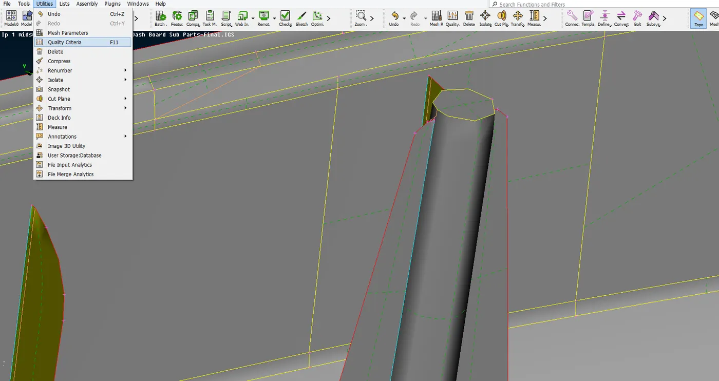
QUALITY CRITERIA
The Quality criteria values are set in the Shells tab as we will be doing Shell meshing in this project.
DE-FEATURING:
De-featuring is a very important process which needs to be done on every model. It is basically removing the construction lines which are not required or violate the quality criteria without compromising on feature capturing.
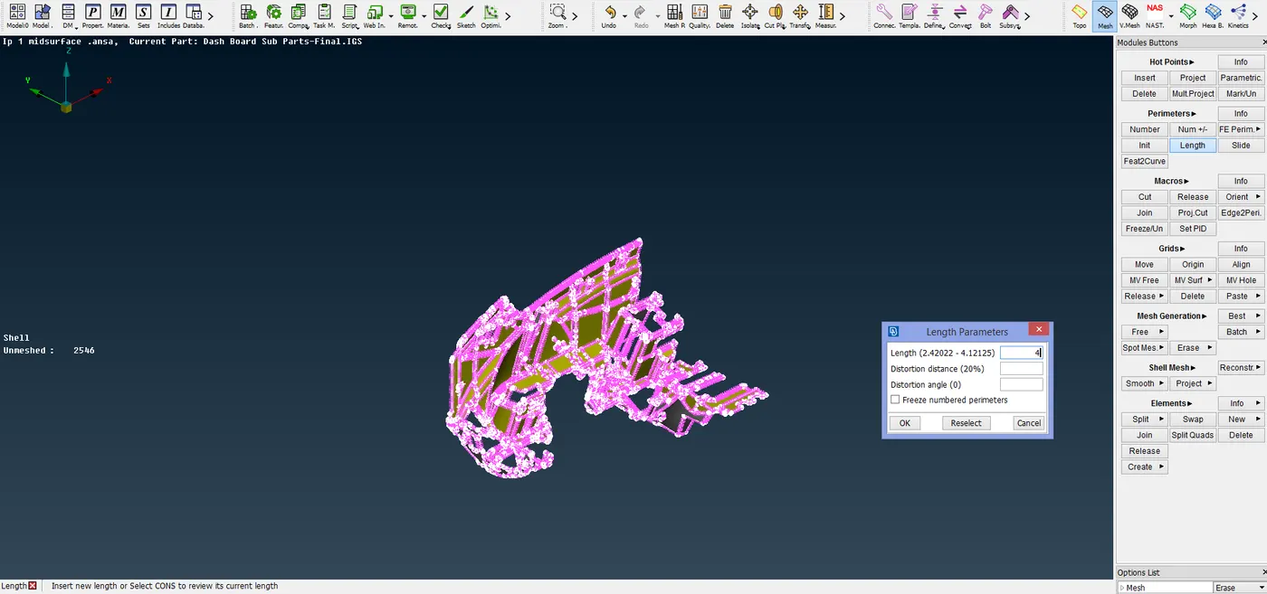
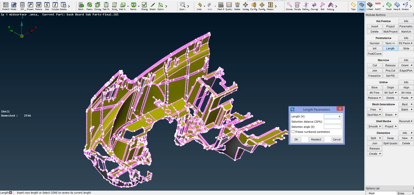
Before the de-featuring is done, the Perimeter length needs to be set. It is done in the Mesh module under PERIMETERS -> LENGTH.
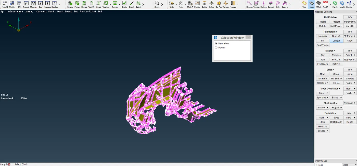
Setting up the perimeter length
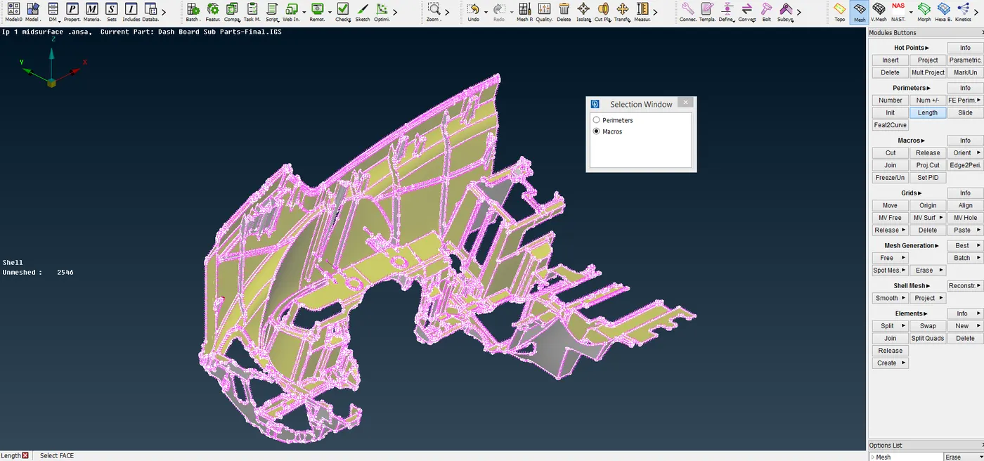
De-featuring is done on surfaces where the constructions lines are much dense. It is done to get a better mesh flow. In such cases, the construction lines are re-arranged using the CUT command under FACES module button in the Topo mode.
Here on one surface, we can see that two construction lines are very close to the fillet line.
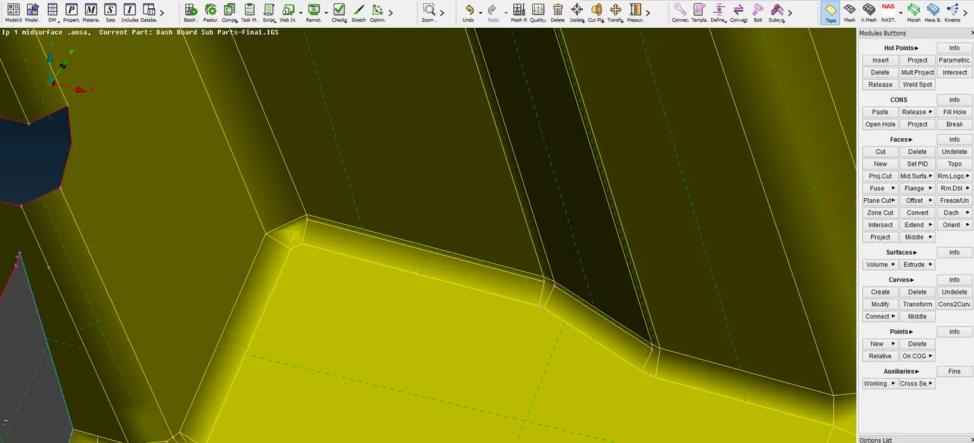
They can be disabled using the FACES -> CUT command.
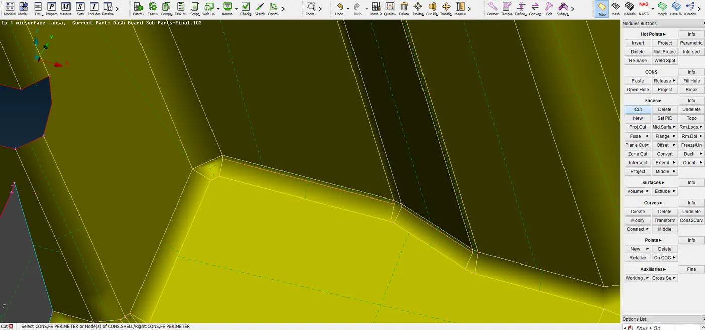
Thus the two construction lines close to the fillet are disabled (orange colour).
Here, we can see a set of surfaces where there are construction lines close to each other.
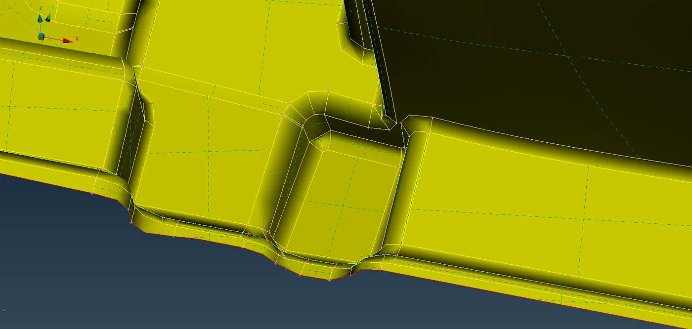
The construction lines need to be re-arranged so that we obtain a better mesh flow without compromising on feature capturing.
The construction lines are re-arranged by creating middle construction line. It is done using the DACH -> DIVIDE FACE which is under the FACES module button in the Topo module.
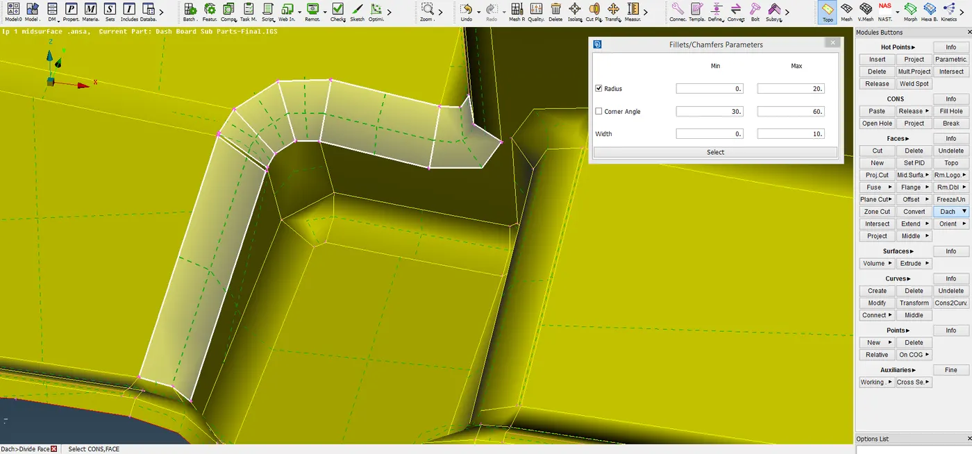
The DACH command
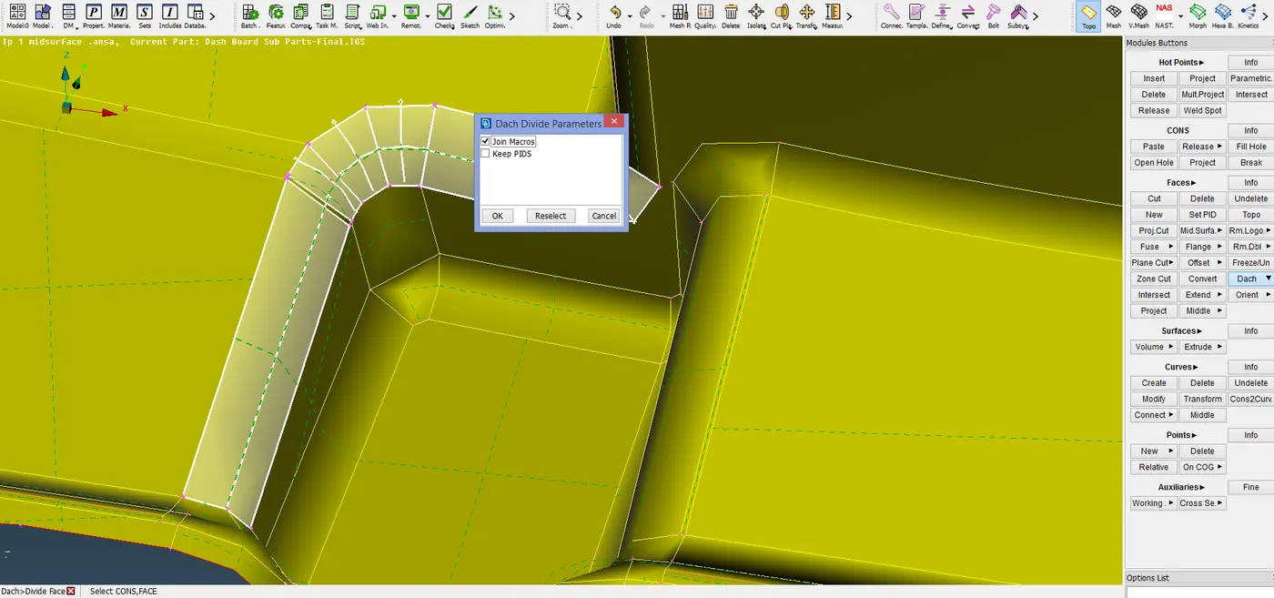
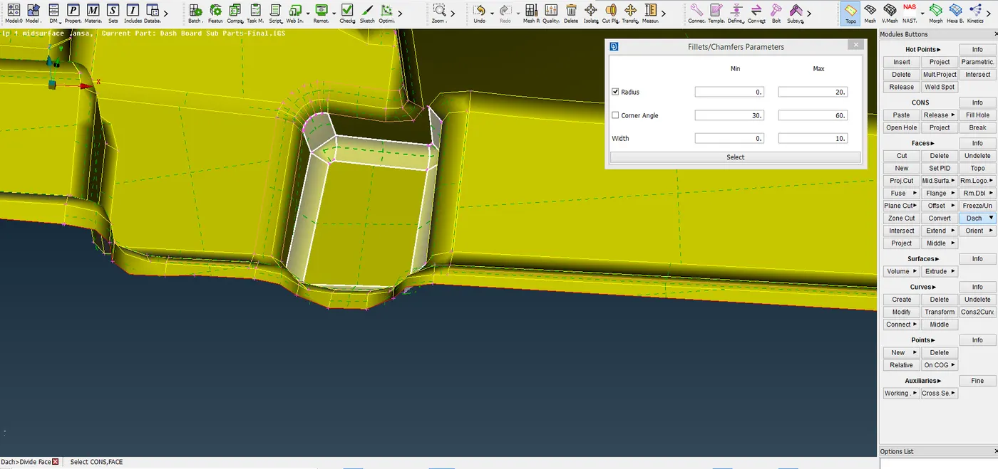
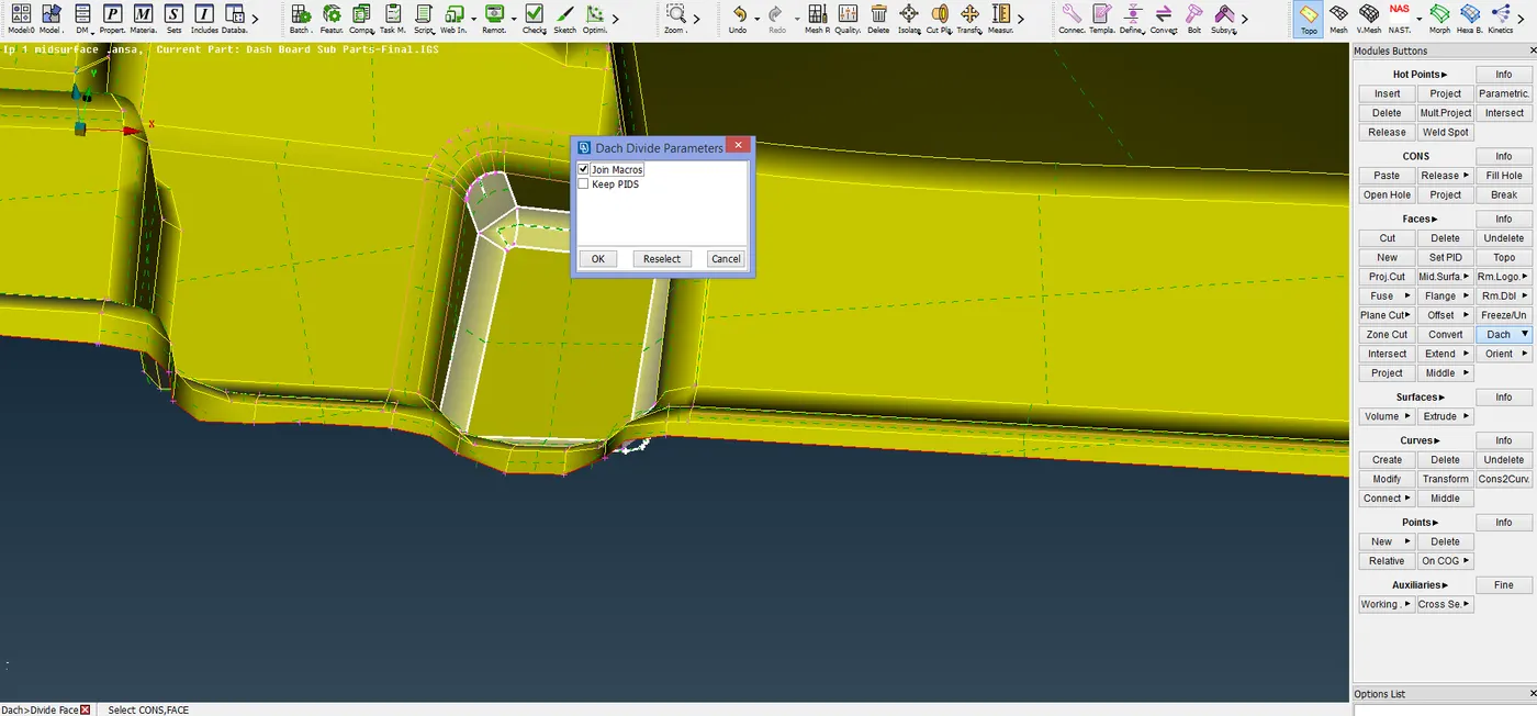
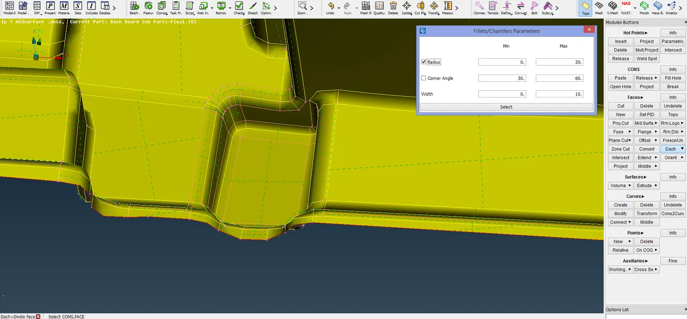
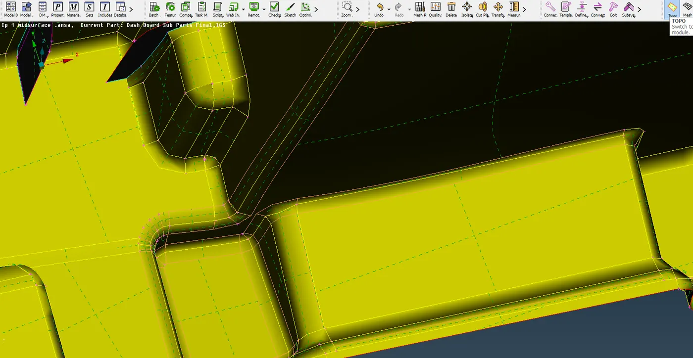
The surfaces can be seen in the Mesh mode to get a better understanding of the feature capturing.
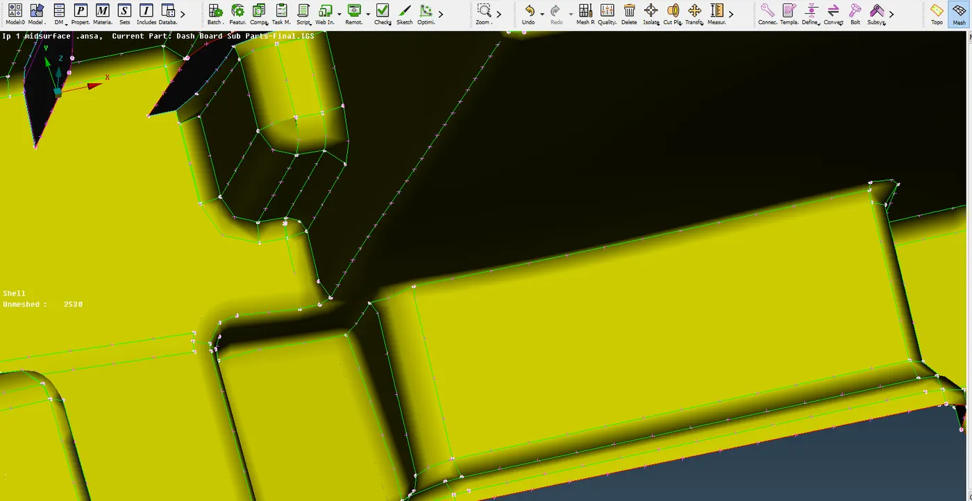
This way, the construction lines are re-arranged without comprising on feature capturing.
De-featuring is done mainly for fillets which are less than the minimum element length.
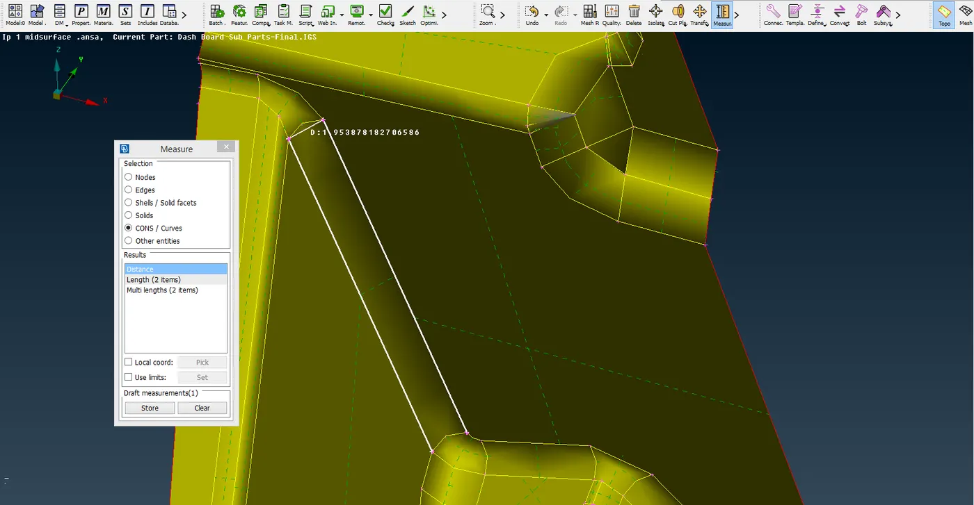
Here, we can see a fillet which is less than the minimum element length quality criteria. For this fillet, de-featuring needs to be done. This is done because when the meshing is done without de-featuring in those surfaces, the mesh elements will fail for quality. Similarly, the de-featuring is done using DACH -> DIVIDE FACE command.
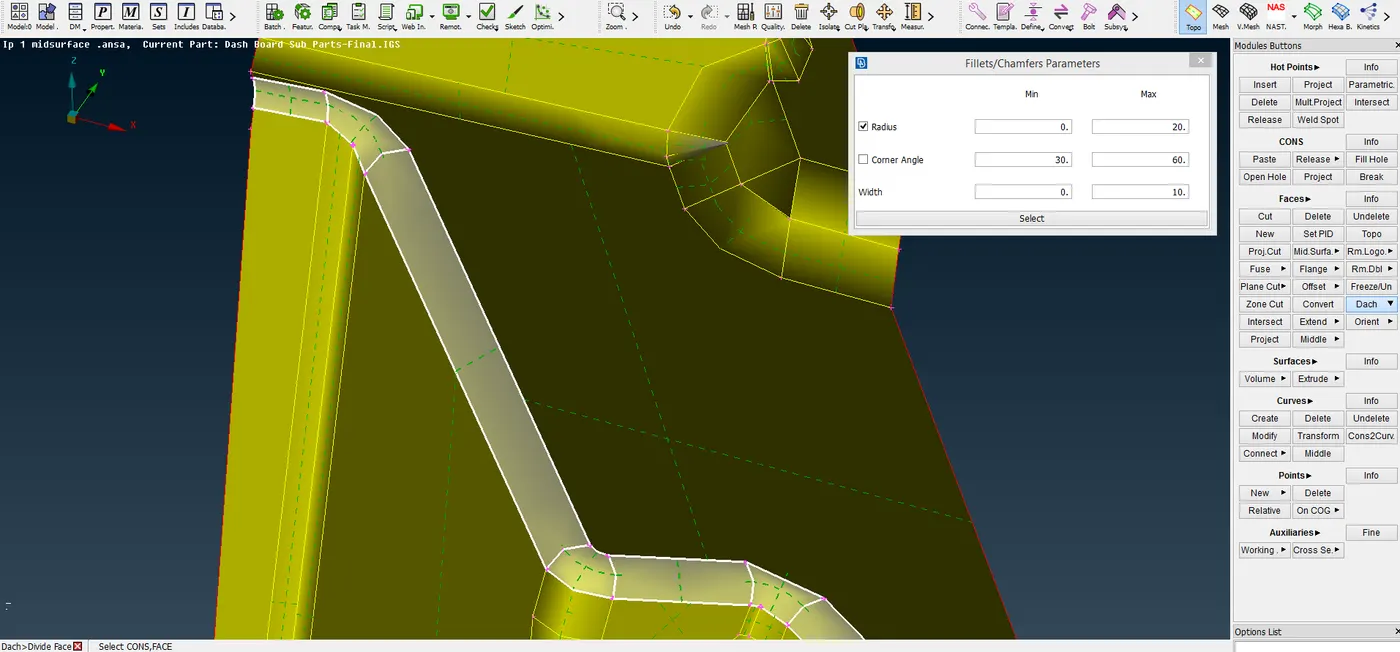
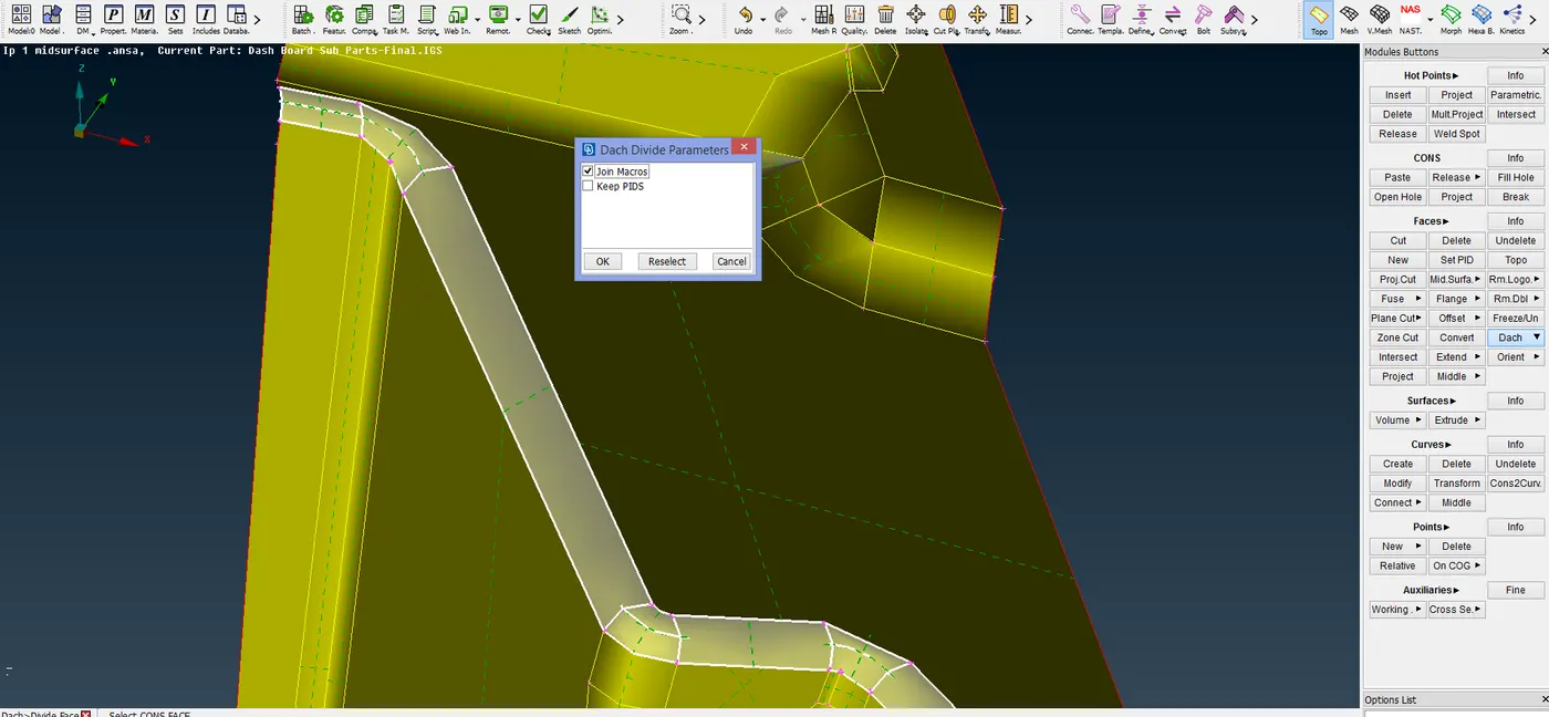
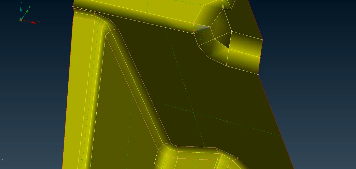
De-featuring is done in similar manner for fillets failing for minimum element length.
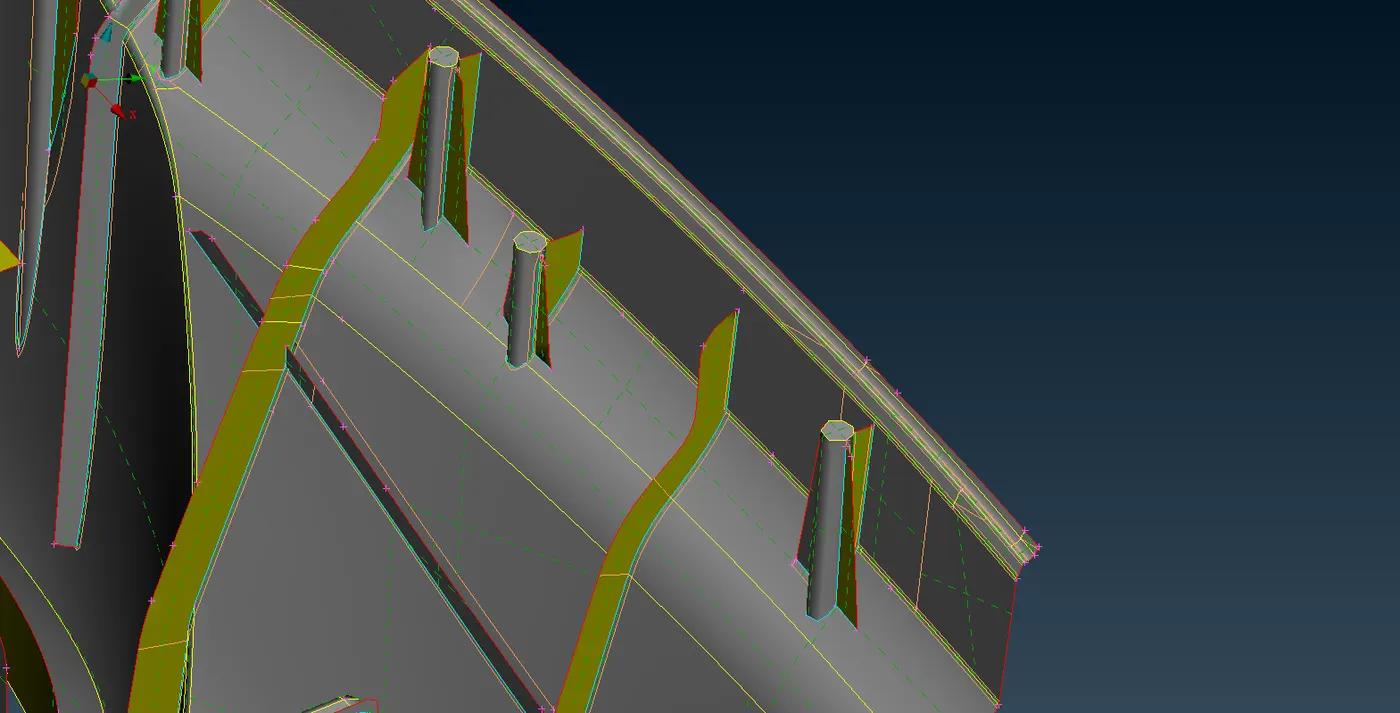
Mid-surface extracted from the Parent surface
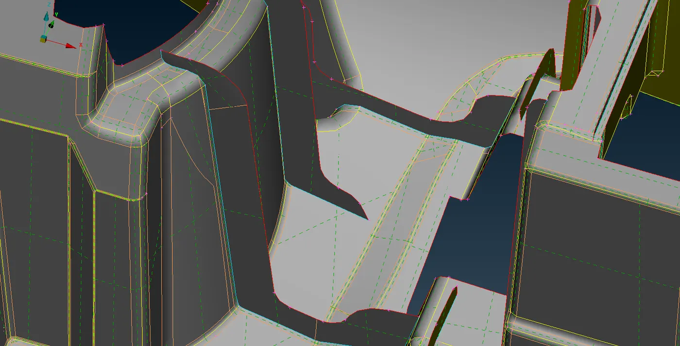
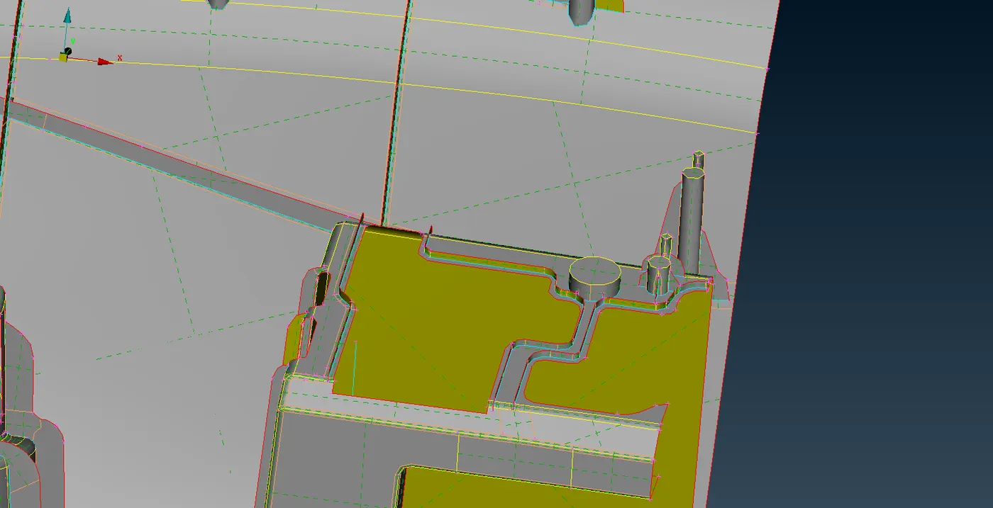
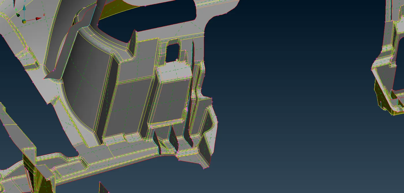
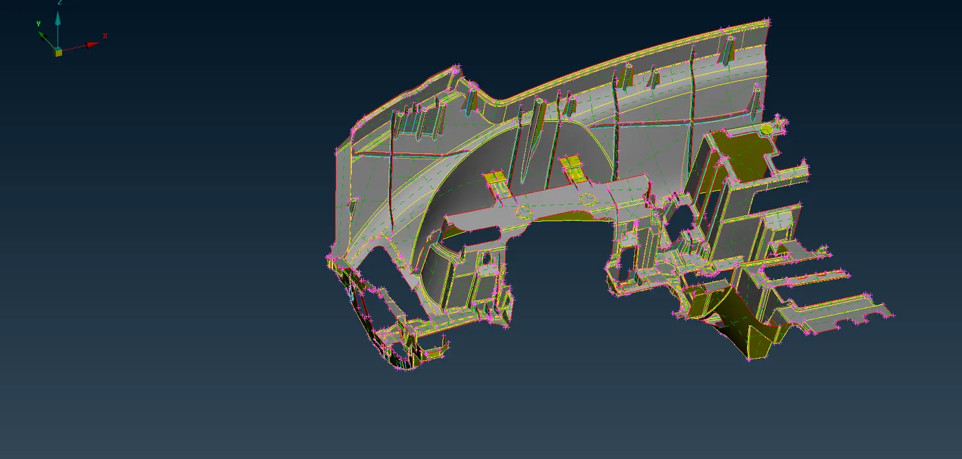
This way, the de-featuring is done on all surfaces as per the requirement and then the meshing is done on the surfaces.
MESHING:
Meshing is done in the Mesh tab. The commands used for meshing are SPOT MESH & BEST MESH. They are under the MESH GENERATION module button.
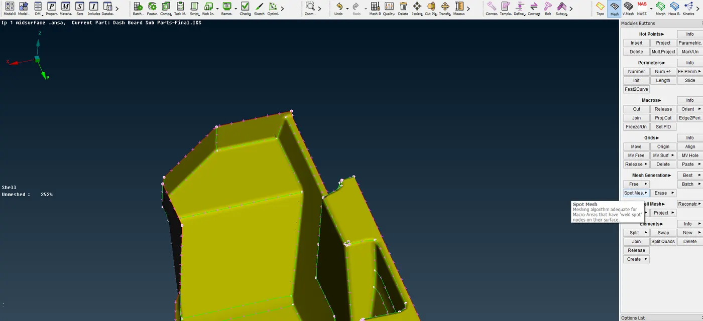
Meshing using the SPOT MESH command
First, the surfaces are selected.
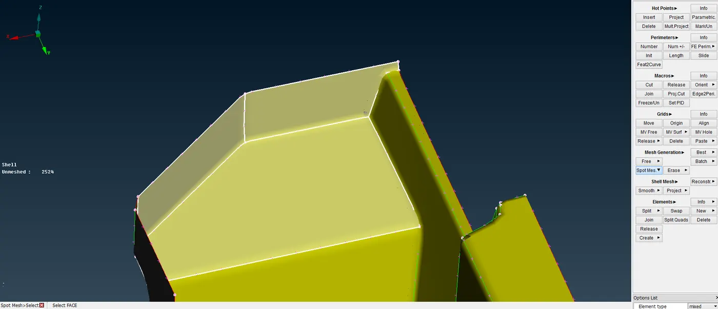
Upon accepting, the mesh is deployed on the surface.
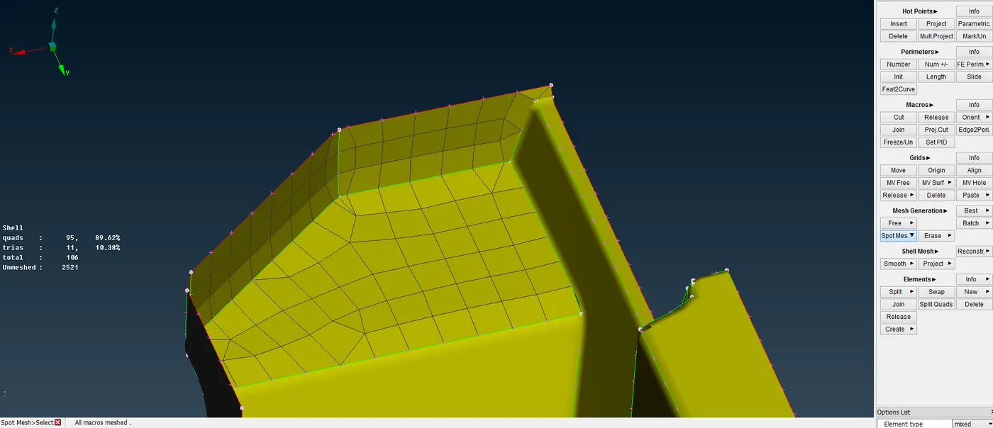
To obtain a better mesh flow, the mesh can be re-constructed using the SHELL MESH -> RECONSTRUCT command.
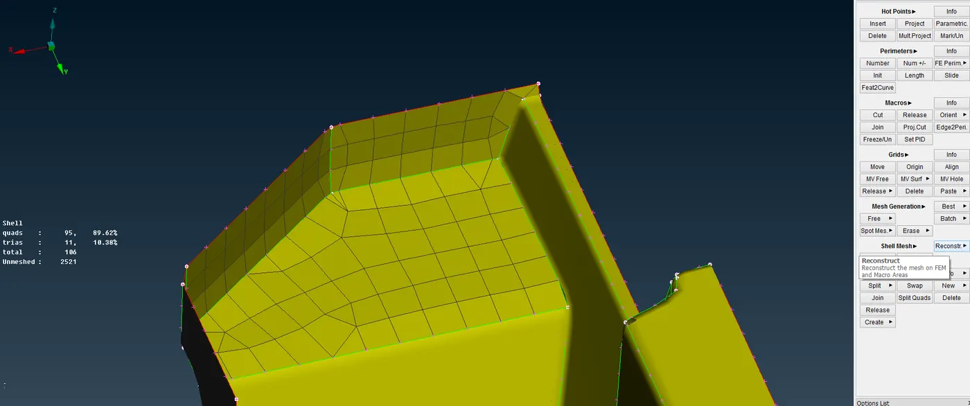
The RE-CONSTRUCT command
After re-constructing the mesh, it can be seen that we have obtained a better mesh flow than the previous mesh.
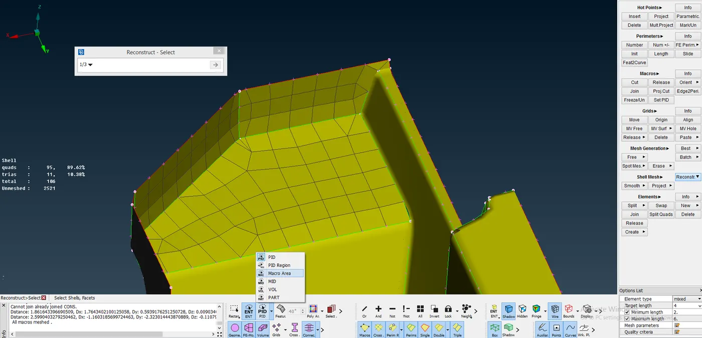
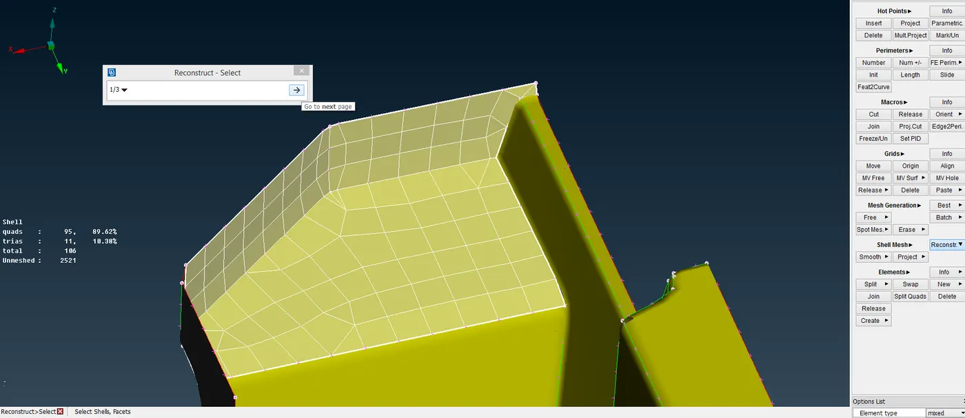
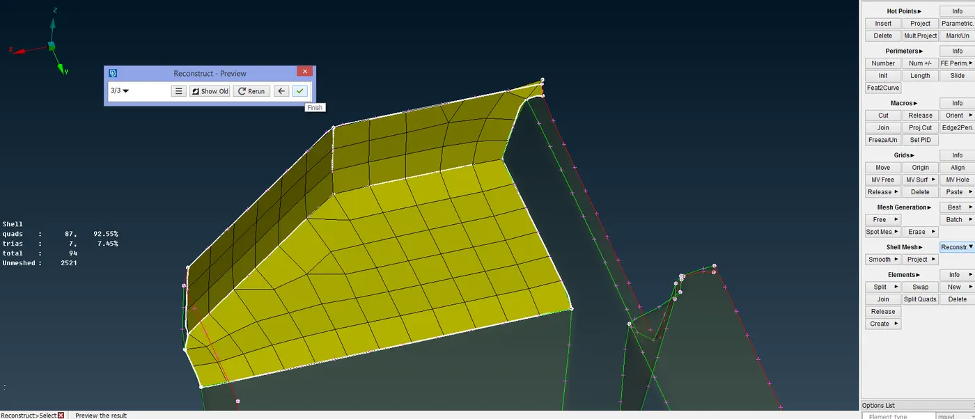
This way, the meshing is done on the surfaces.
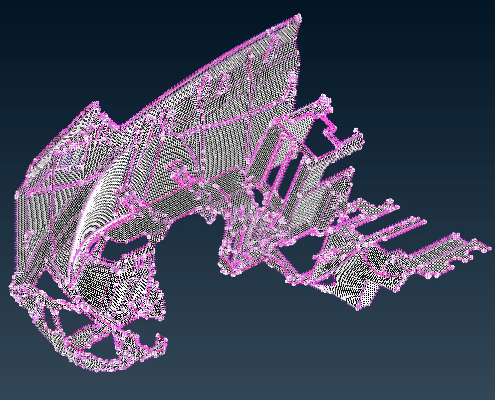
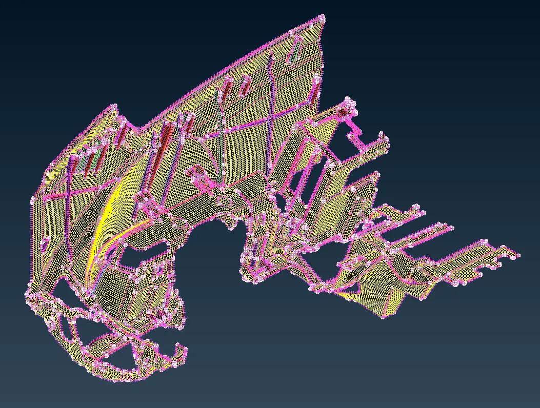
RESOLVING QUALITY ISSUES:
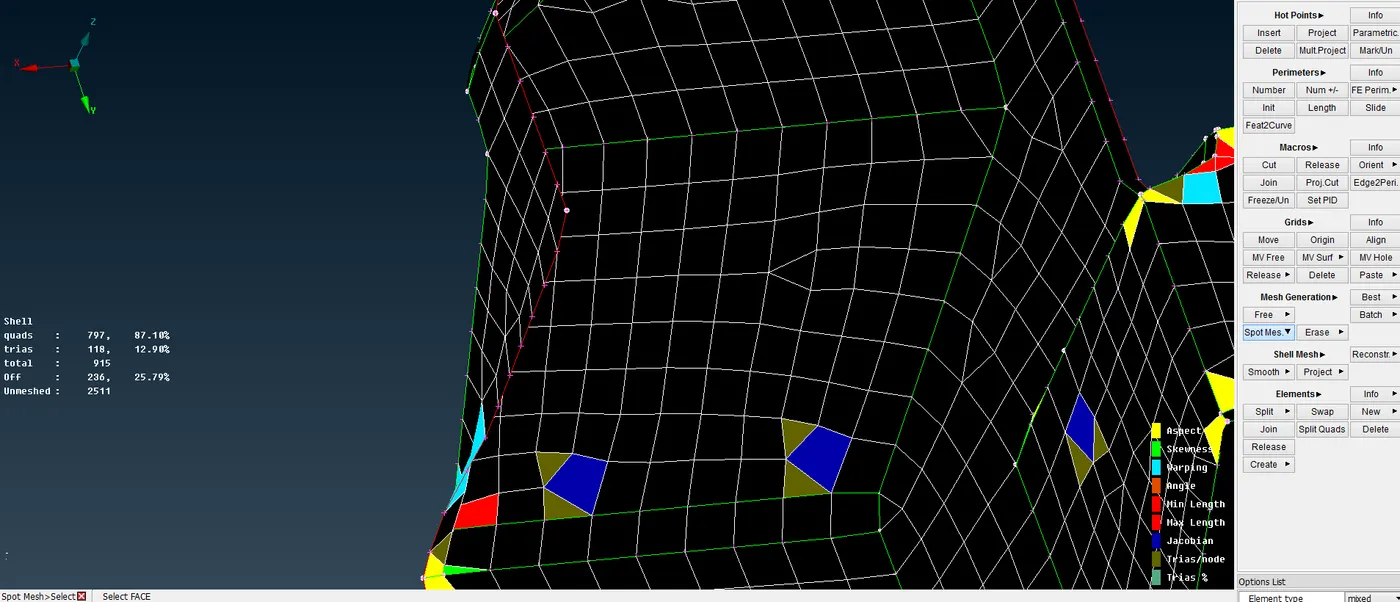
Once the meshing is done, the quality issues need to be solved. The elements failing for quality need to be rectified. They can be seen only in the HIDDEN mode.
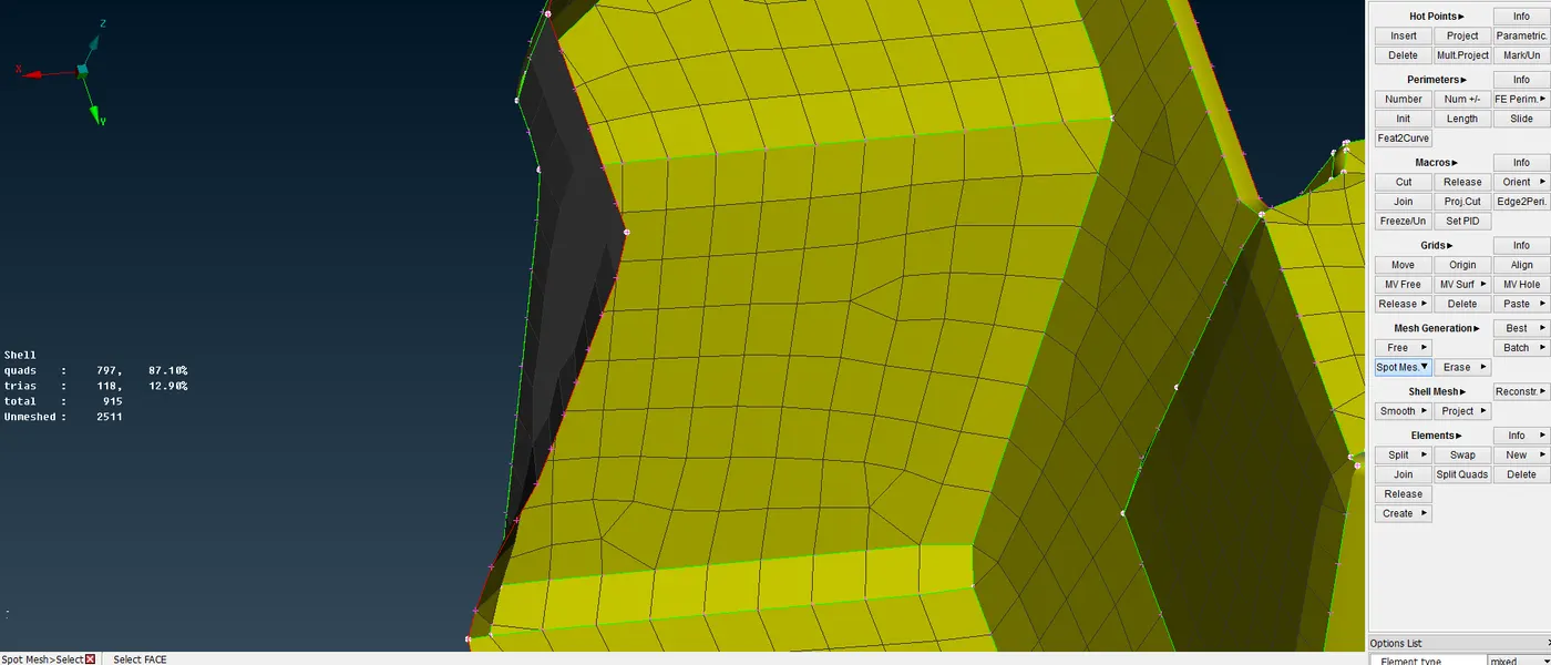
Here we can see that even though the mesh is proper, there are failing elements in the mesh which were not visible in the SHADOW mode.
These failing elements need to be resolved. This can be done by using RECONSTRUCT command. This is one method. The another method is by using the SPLIT command. It is under the ELEMENTS module button.
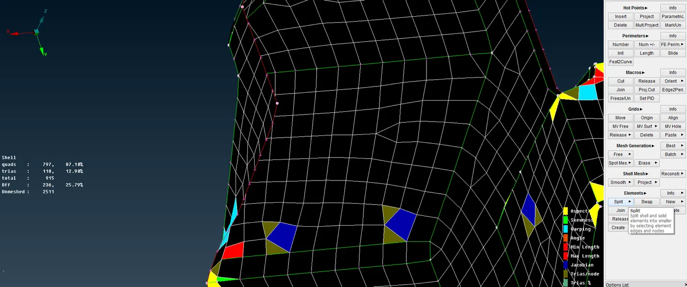
The ELEMENTS -> SPLIT command
This command is used to split quad elements into trias by selecting its nodes or edges.
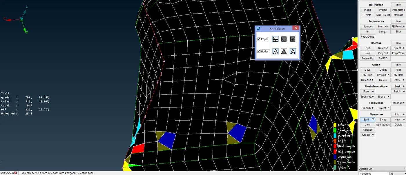
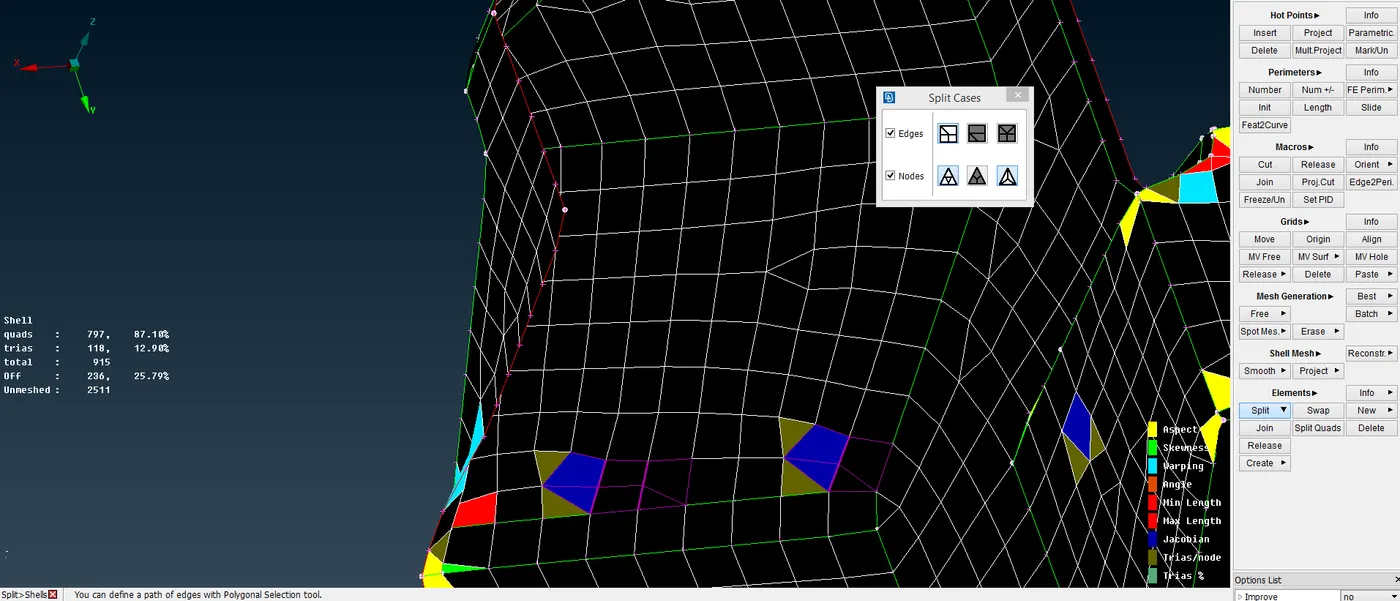
The edge of the quad element is selected and the split is done.
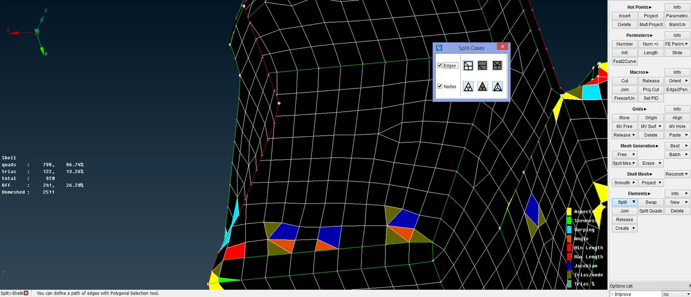
Then we can see two tria elements. They can be joined to form a quad element. This is done by using the JOIN command. It is under the ELEMENTS module button.
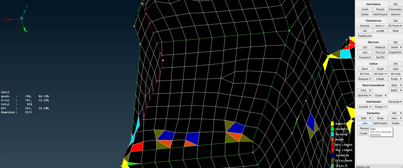
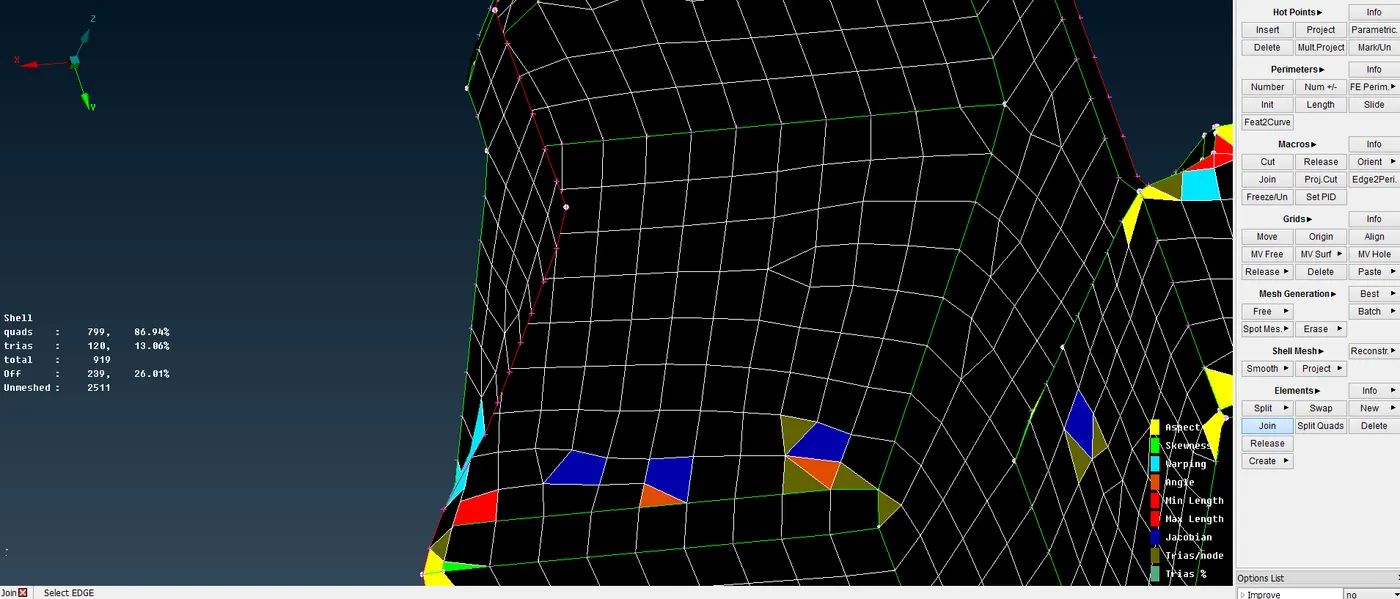
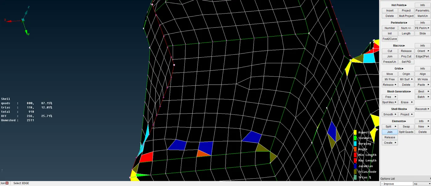
Now, we can see the mesh flow has been distorted. The SMOOTH command can be used to smoothen the mesh flow.
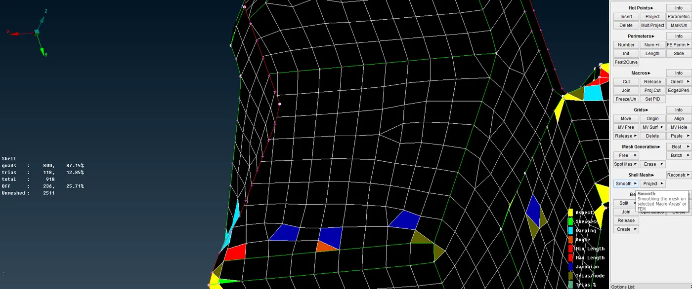
SHELL MESH -> SMOOTH command
After the command is selected, the mesh elements are selected. Upon accepting, the existing mesh is smoothened to get a good mesh flow.
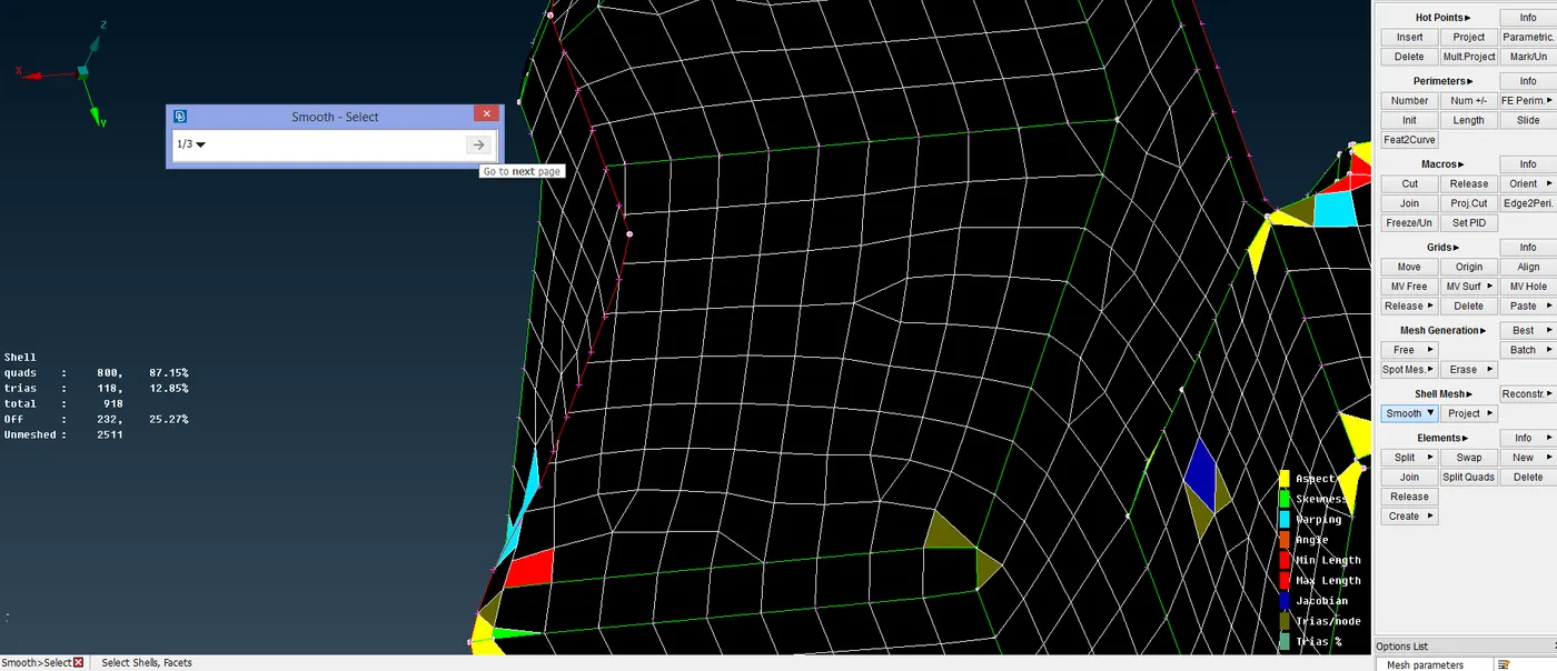
After resolving the quality issues, we will get a proper & good mesh flow.
It can be seen that the quality criteria cannot be met at some places. This is due to reason that the geometry is quite complex with construction lines. Therefore it is not possible to obtain a mesh flow that passes the quality criteria 100%. If we were to obtain a mesh flow that passes the quality criteria 100%, we would need to compromise on the feature and surface capturing.
ASSIGNING THICKNESS TO THE MID-SURFACE:
The mid-surface is assigned thickness in the Quality criteria (UTILITIES tab or F11) dialog box.
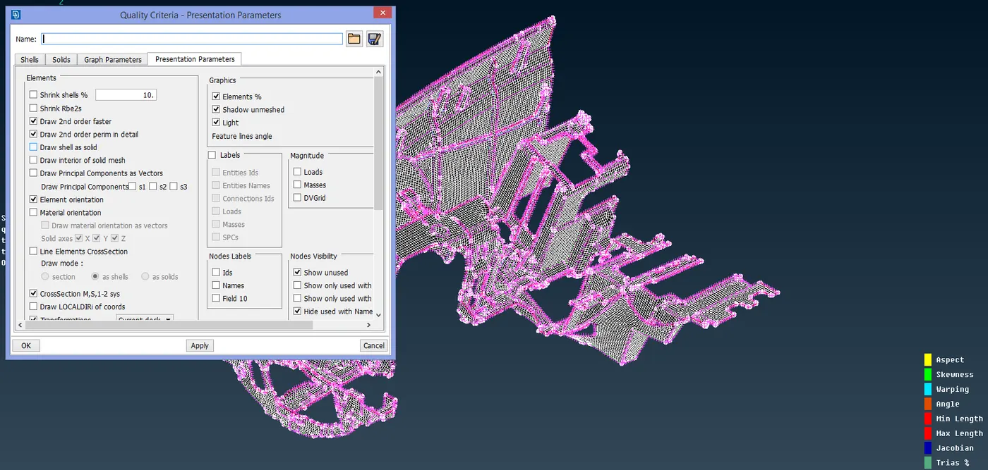
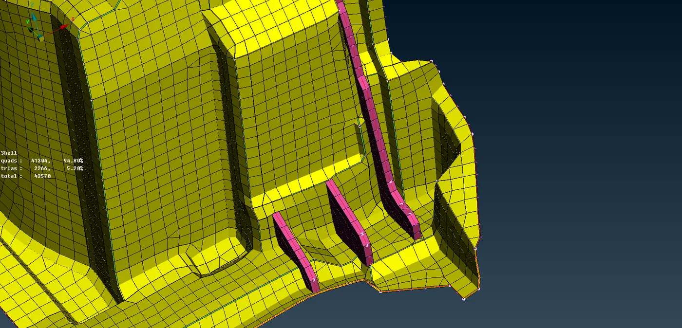
In the Presentation parameters tab, the “Draw shell as solid” checkbox is enabled and then the changes are applied.
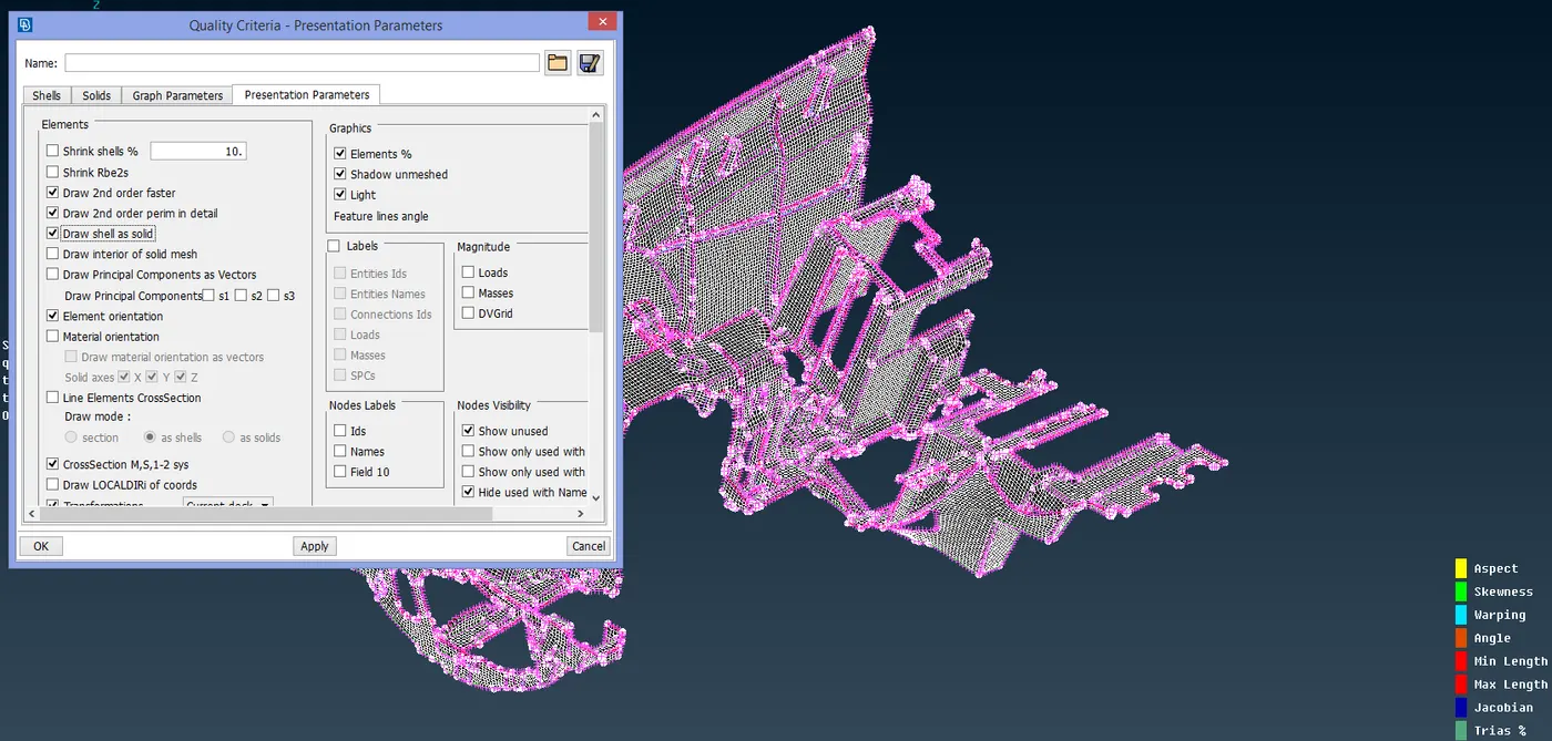
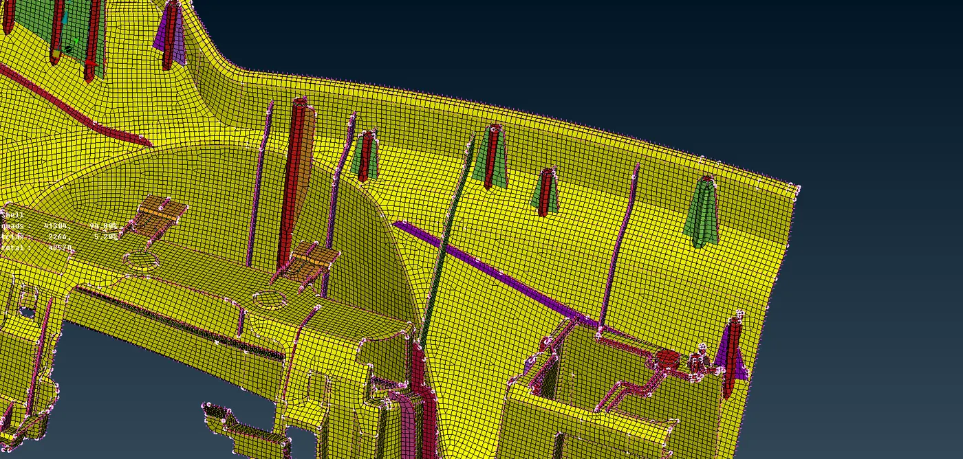
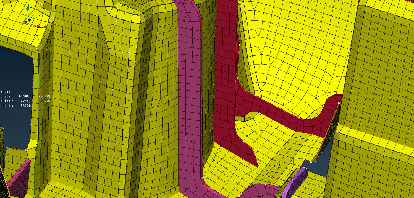
After this option is enabled, the existing shell mesh is converted to solid.
LEARNING OUTCOME:
From this project, the following are learnt:
1. Performing geometry checks and geometry cleanup.
2. Mid-surface extraction of the plastic components such as an instrument panel substrate.
3. De-featuring the mid-surface.
4. Meshing the mid-surface & Assigning thickness.
5. Also the methods of resolving quality issues in the FE model to obtain a good mesh flow are learnt.
CONCLUSION:
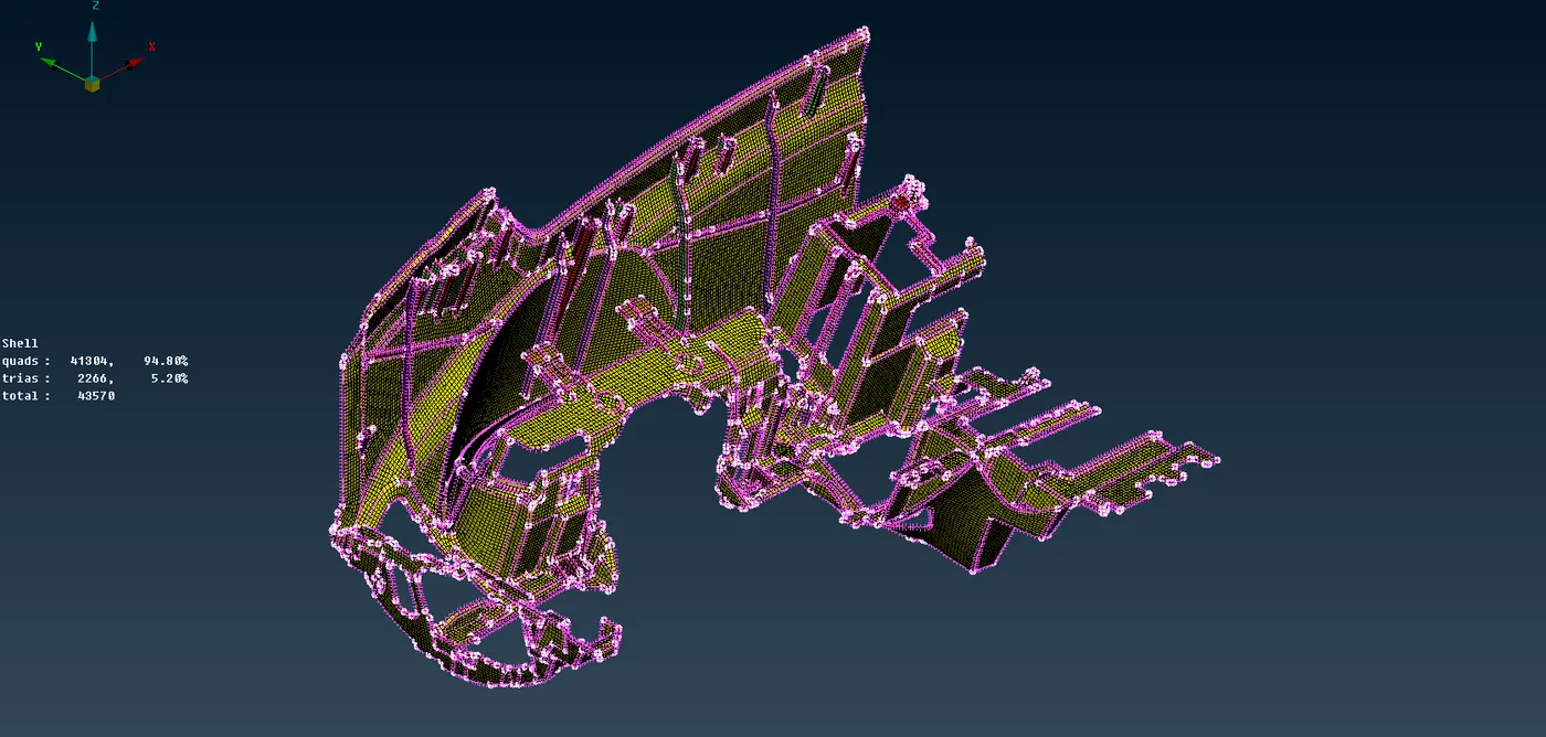
Thus the given Instrument panel substrate model is mesh with the given quality criteria.
Quad elements: 41304 (94.80%)
Tria elements: 2266 (5.20%)
Total elements: 43570
- Bimlendra RayActually, what is the percentage of tria in your component? Is there a jacobian and warpage issue too? Anyway, it seems good.