Simulating a doorbell & thermistor in Simulink
AIM:
- To make a Simulink model of a doorbell using the solenoid block.
- To make a Simulink model to use the thermistor to sense temperature of heater and turn on & off fan as per given conditions.
OBJECTIVE:
The objective of this project is to learn to solve problems by simulating using Simulink with basic models.
MODEL SETUP:
Doorbell:
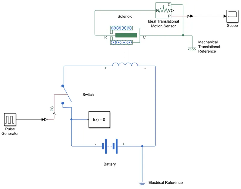
Condition: According to the given condition, we have to keep the switch closed for two seconds and then release the switch.
In the model setup, we have a battery, which is the voltage source in the circuit. There is a switch which opens & closes the circuit, a solenoid block to which the translation motion sensor is connected. The input is given from the pulse generator block to the switch. The switch block is a type of block which is closed when the received input is above the threshold value. If the input is below the threshold, the switch block will be open. The output is obtained from the translation motion sensor in the Scope block, where we have a plot of the movement of the arm(plunger). Also there is a Solver configuration block. Keeping the solver configuration block is necessary as we are using the Simscape block-sets. We also have a Electrical reference and Mechanical translational reference. It is necessary to use Electrical & Mechanical references when the respective blocks from the block-sets are used.
Thermistor:
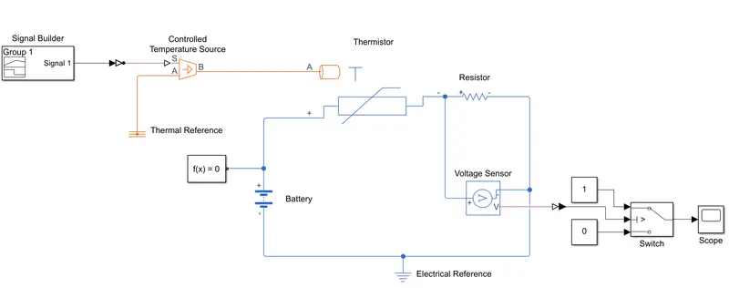
Condition: Fan conditions- ON if the temperature is above 25° C, otherwise OFF. (Temperature source: 20 °C from 0 to 10 seconds, 27 °C from 10 to 30 seconds, 23 °C from 30 to 50 seconds).
In the model setup, we have a battery, which is the voltage source in the circuit. There is a Controlled temperature source, a Thermistor and a resistor. A Thermistor is basically a resistor whose resistance depends on the temperature. In this case we have a NTC (Negative Temperature Coefficient) type thermistor. For NTC thermistors, the resistance decreases as the temperature increases. The resistor is of a known resistance which is used to know the threshold value of the thermistor. A Voltage sensor block (Voltmeter) is also connected between the two terminals of the resistor. The physical signal output from the voltage sensor is given to a Switch block through the output plot is obtained in the scope.We also have the Solver configuration block. Since we have blocks from Thermal and Electrical block-sets, we have connected Thermal reference and Electrical reference. The input for the Controlled temperature source is given through the Signal builder block which generates signals as designed in the block manually.
THEORY:
Doorbell: In Simulink, we do not have physical components such as a Doorbell or a plunger. Instead we can use the available blocks which can serve the purpose of a doorbell or a plunger. As a replacement of the plunger, we have the Translation motion sensor block, which detects translation motion and instead of the doorbell, we have the scope block, which shows visual output of the movement of the translational motion sensor block.
Thermistor: Similarly, in this case, instead of a fan, we have a switch block and a scope through we can see the output visually. For a temperature source, we have the Controlled temperature source block which maintains the specified temperature difference across the source. Measuring the voltage across the two terminals of the resistor is done using the Voltage sensor block. It acts as the Voltmeter.
EXPLANATION:
Doorbell: The input from the pulse generator block is given to the switch block through the PS-Simulink converter. It is used to convert physical signals to Simulink signals. When the input is more than the threshold value given in the switch block, the switch is closed and the circuit is complete. When the circuit is complete and closed, the current flows through the coil. Through the solenoid, the iron core inside excites and the movement of the arm is facilitated. This movement is detected by the Translational motion sensor block. The output from the sensor block is again converted to Simulink signal using the PS-Simulink converter and sent to the Scope where the plot is obtained.
Thermistor: First the threshold for the found out by giving the temperature input at 25° C. When the threshold is found, the signal is built in the signal builder and the same is given as input to the Controlled Temperature source through the Simulink-PS converter. This is done to convert the Simulink signal to a physical signal. One port in the source is given to the Thermistor and the other port is used for Thermal reference. In the main circuit, we have a battery which is the voltage source of 12V. The positive of the battery is connected to the positive of the Thermistor and the negative of the Thermistor is with one terminal of a resistor which is of known resistance. A voltage sensor block is connected across the terminals of the resistor. The physical signal output from the voltage sensor block is given to the Switch block. This switch block is a different one from the one used in the previous case. When the input received in port 2 is satisfies the criteria given, the output is passed from the port 1, or else the output is passed from the port 3. The inputs at port 1 and 3 will be given as 1 and 0. The output is then given to the Scope.
RESULTS:
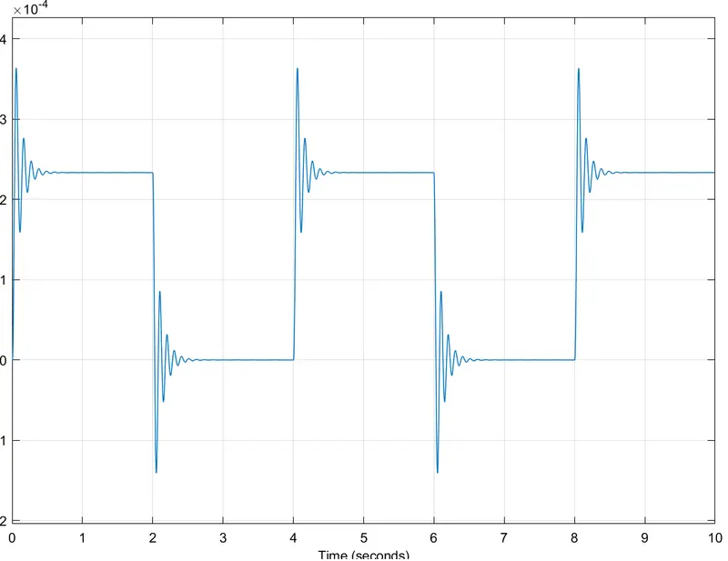
In the output plot, we can see a step-function with ups and downs in the curve. When looking at the time axis (x-axis), we see a difference of 2 seconds for every peak and trough in the curve. This in-turn indicates the opening & closing of the switch for every 2 seconds.
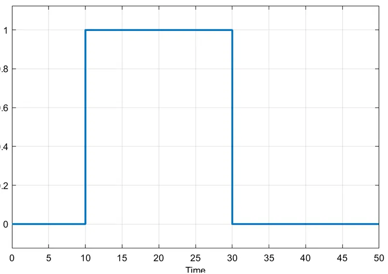
In the second plot, we can see a step curve. In the time axis (x-axis), we can see that the peak is from 10 to 30 seconds. The value on the y-axis is 1. For other time values, we can see the y value is zero. This shows that the on position for the fan is from 10 seconds to 30 seconds and at other time values the fan is at off position.
CONCLUSION:
Thus the Simulink model is done and the required output is obtained in the form of plots.