Week 9-Creation of 1D Connectors Challenge
AIM:
To mesh the given model and create connectors and attach the various parts of the given model.
OBJECTIVE:
The objective of the project is to learn the different connectors and welds in Hypermesh and deploy them.
PROCEDURE:
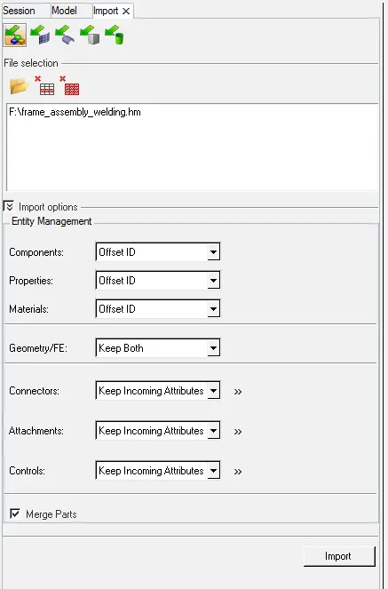
First the model is imported using the Import model option.
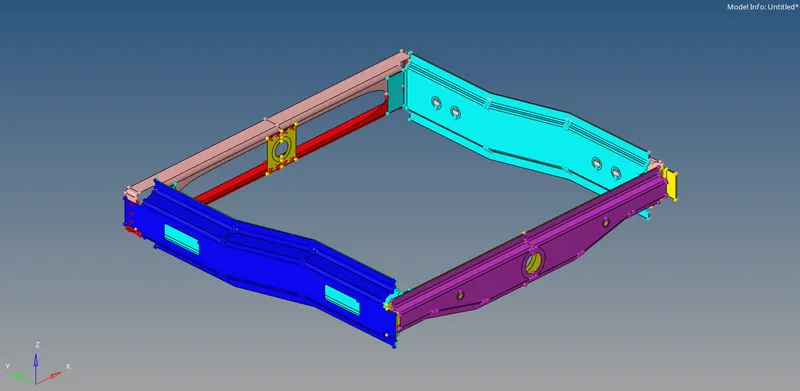
Then the geometry is kept in Topo mode so that all edges in the model can be seen clearly.

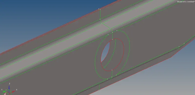
The geometry cleanup is done on the model by toggling free edges. Here we can see that there are two surfaces intersecting but there is a free edge. So this kind of free edges are toggled.

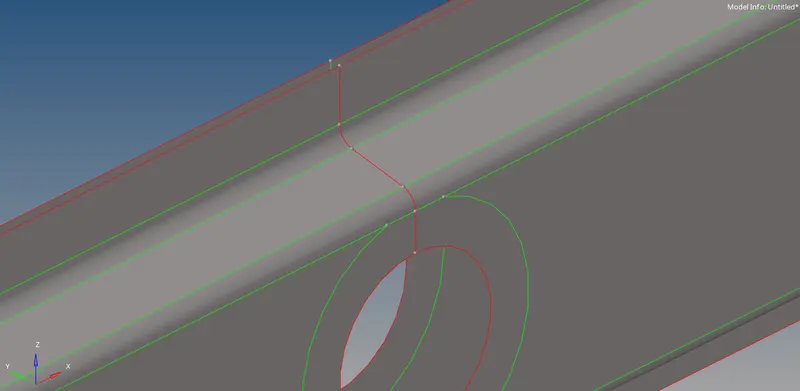
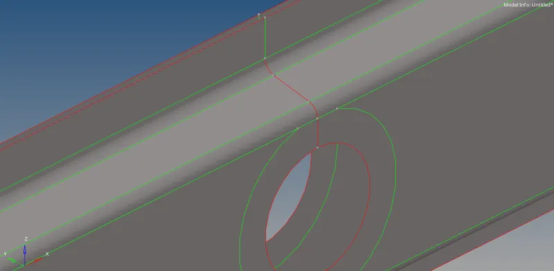
Then the meshing is done in the automesh command button (F12) by selecting the model.

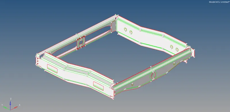
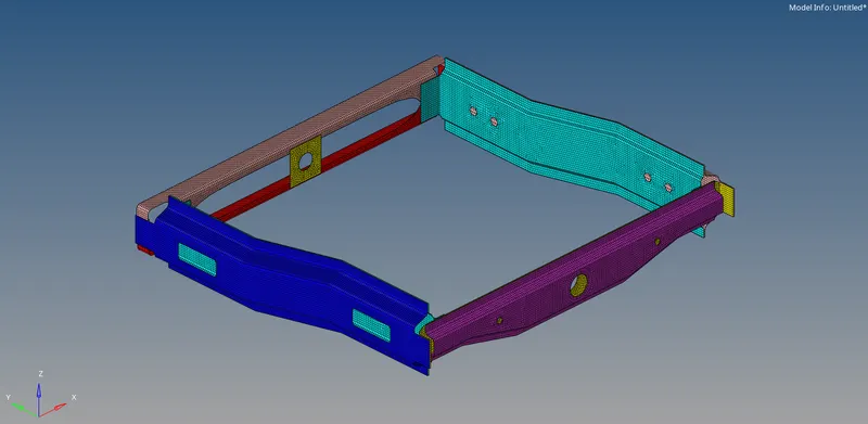
Then the connectors section is opened which is inside the 1D, connectors panel.


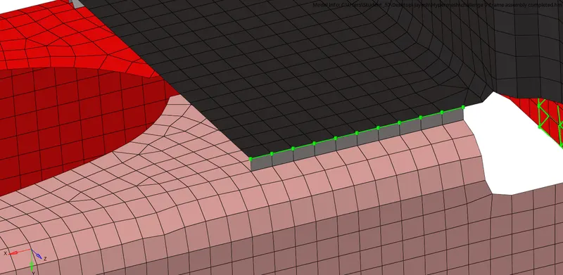
First, the location where the connection is to be given is taken. Here we are giving seam connection.
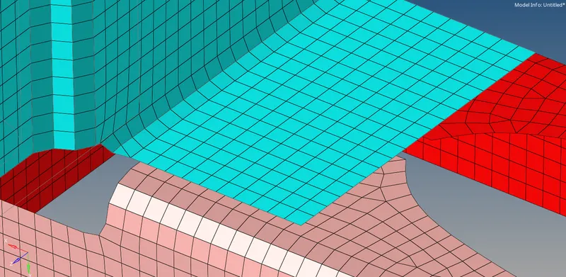
The connection parameters are set. In type, the angled+capped+L option is selected.

The nodes are selected and the components between whom the connection is to be given is selected and the connection is created.
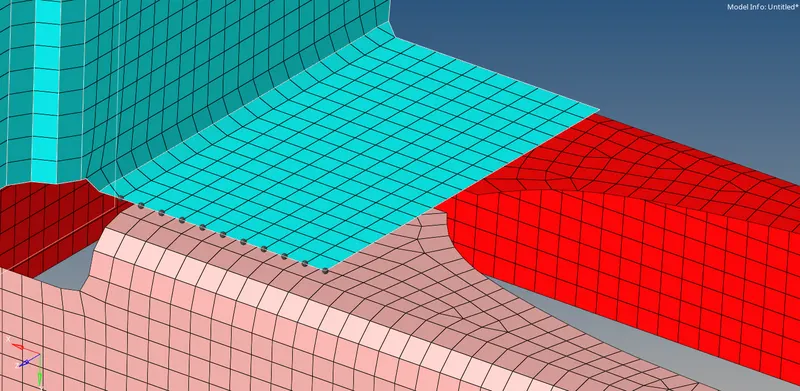
For seam weld using Quad elements, the same process is followed. In type, the Quad option is selected.
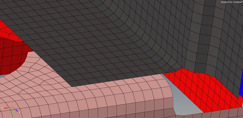

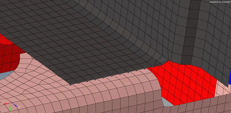
For spot weld, we will go inside the spot command button inside connectors.

The location where the connection is to be given is taken.
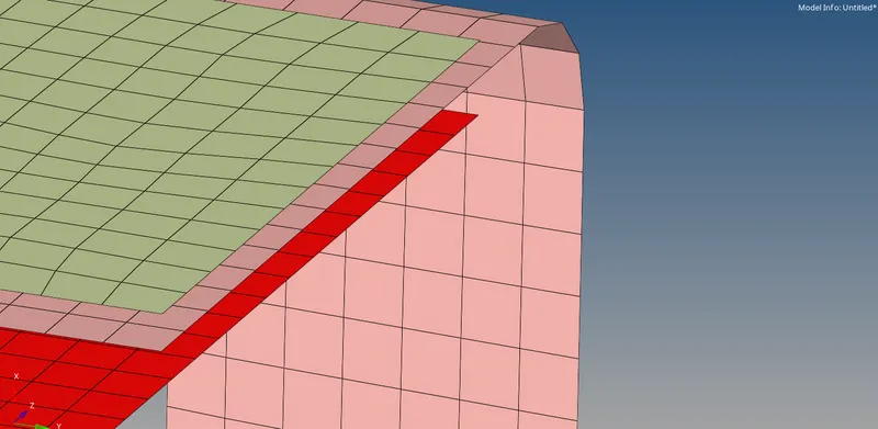
The connection parameters are set. In type, the weld option is selected. For num layers 3 Layers and for diameter 5 mm is given.
The nodes are selected and the components between whom the connection is to be given is selected and the connection is created.
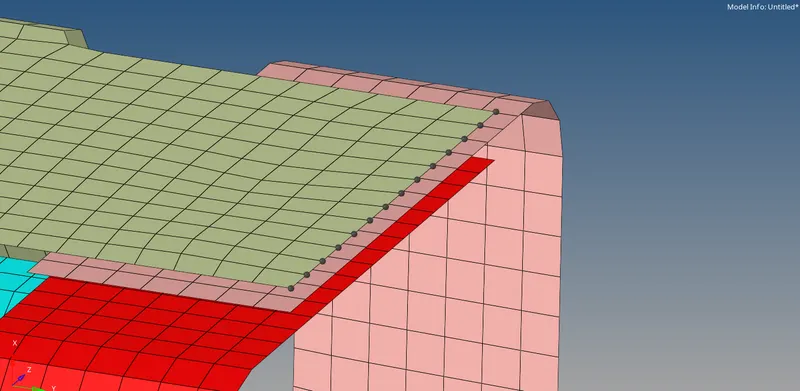
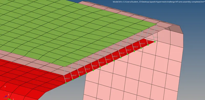
The next connection we are giving is adhesives. This is given inside the area command button inside connectors.
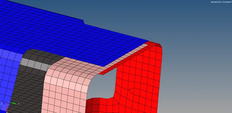
The location where the connection is to be given is taken.

The connection parameters are set. The width and FE type are selected. Also the no. of coats is given.
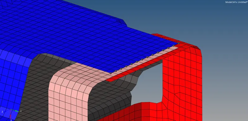
Then the nodes are selected and the connection is created.
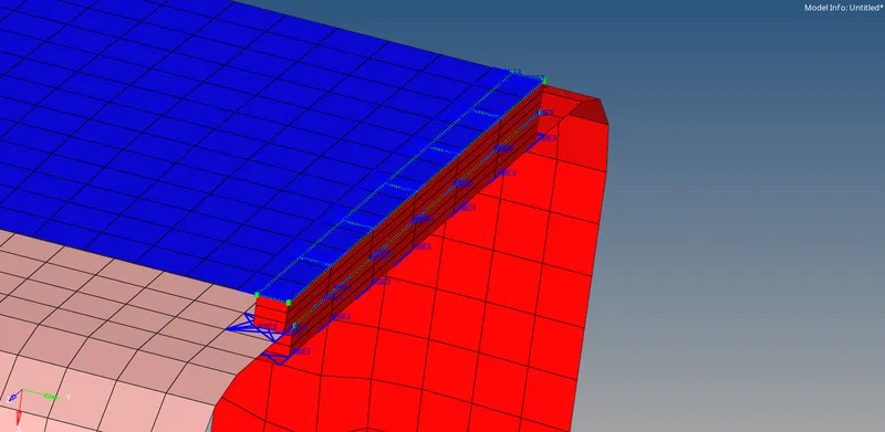
The next connection is bolt connection. The location where the connection is to be given is taken.
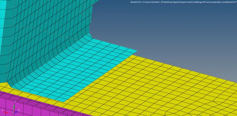
If we already have a hole with a washer split, the nodes surrounding the hole are selected. If we do have a hole, a single node is selected. The connection parameters are set. The create hole if none option is kept as we do not have a hole created.

Then the connection is created.
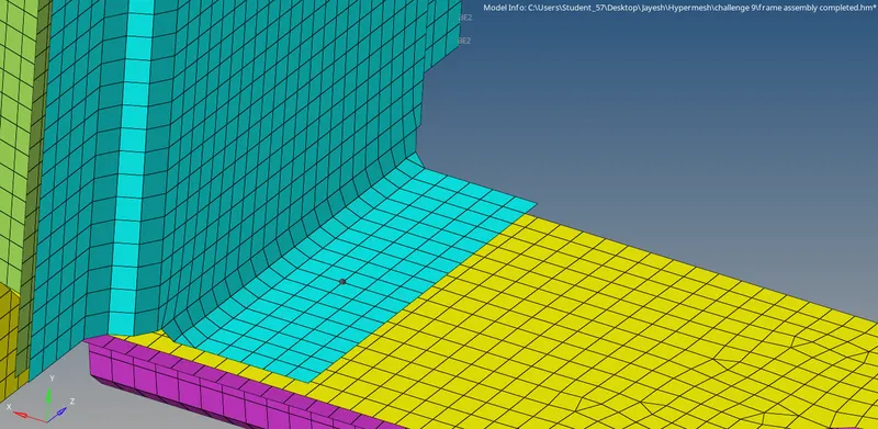
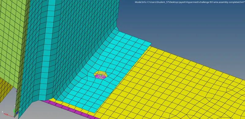
The same way, another bolt connection is given.
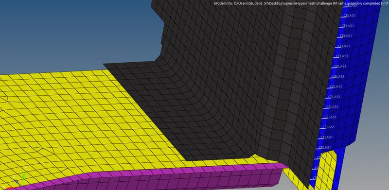

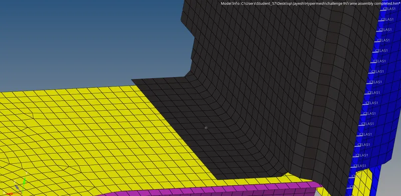
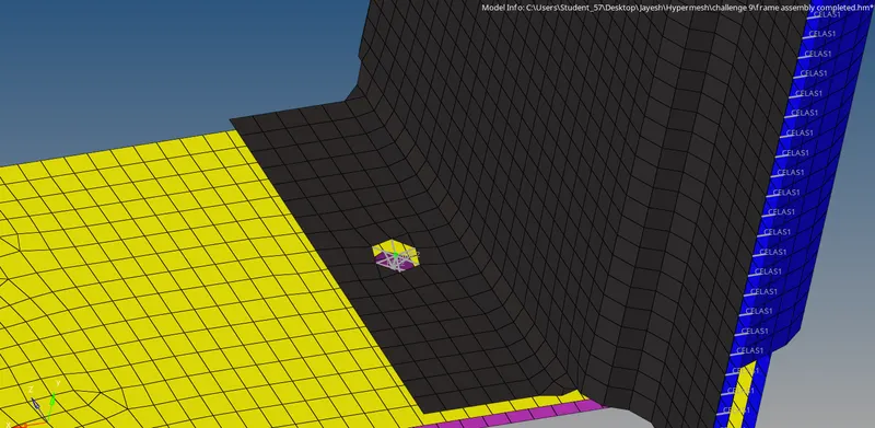
For spot weld using rigids, we should be inside the spot command button in the connectors.
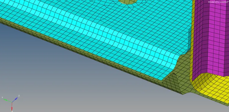
The nodes are selected and the components between whom the connection is to be given is selected. The connection parameters are set. In type, the rigids option is selected.

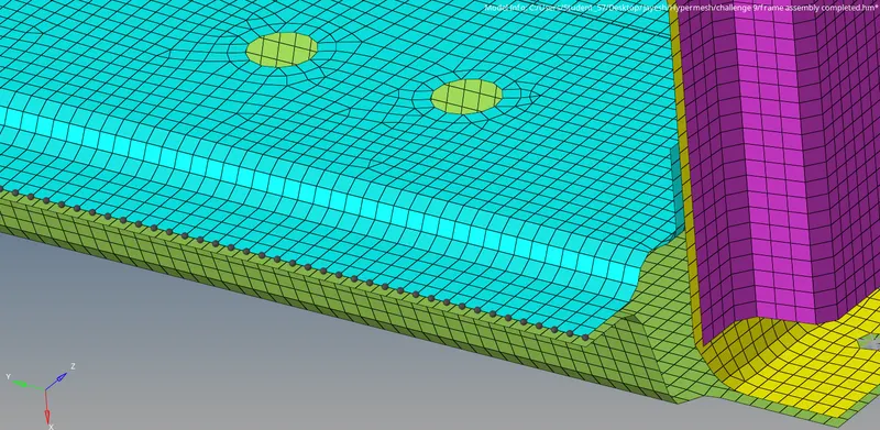
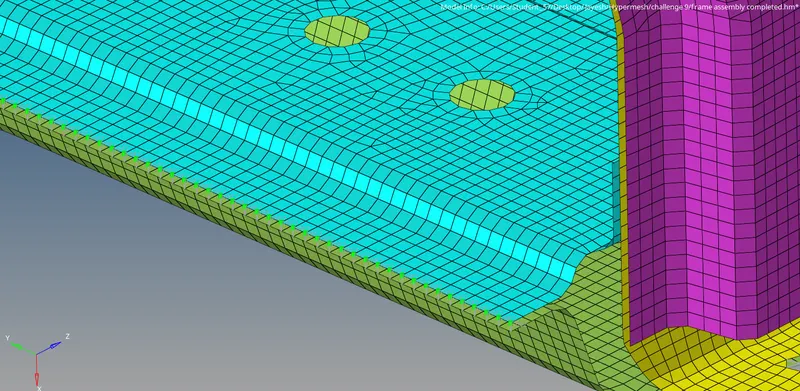
For spot weld using spring elements, the same process is followed. In type, the spring option is selected.

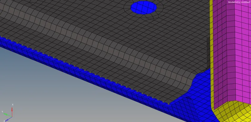
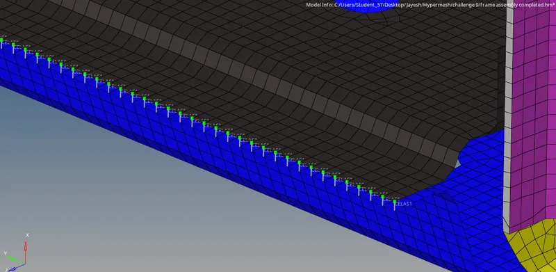
RESULTS:
Seam-Quad(angled+capped+L):
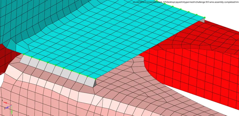
Seam weld (Quad elements):
Spot weld with 3 Layers and 5 mm Diameter:
Hexa (Adhesive):
Bolt Connector 1:
Bolt Connector 2:
Spot-weld with Rigid Elements:
Spot-weld with Spring Elements:
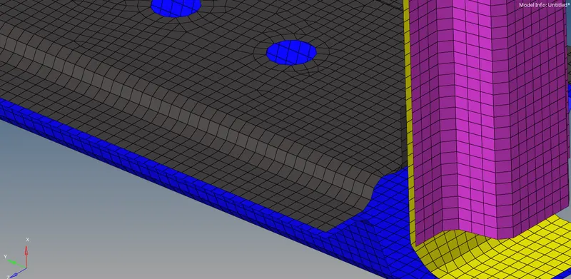
Completed model:
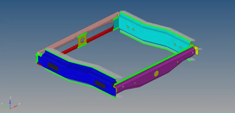
CONCLUSION:
Thus the connections are given as specified with required parameters.