Week-6 Challenge: EV Drivetrain
AIM:
- To know the types of power converters circuits employed in HEVs & EVs.
- To calculate the steady state speed for an EV with the given parameters.
- To refer to the Induction Versus DC Brushless Motors blog and briefly explain about the topic discussed.
OBJECTIVE:
- To study the different types of power converters used in HEVs & EVs.
- To understand the steady state condition of the motor & vehicle characteristic curves.
GOVERNING EQUATIONS:
- Angular speed `omega =V/(kphi)-(R_a/(kphi)^2)*T`
where,
V = Effective voltage (V)
kɸ =Motor speed constant
`R_a` = Armature resistance (Ω)
T = Torque (Nm)
- Roots of the quadratic equation `ax^2+bx+c` is given by
`x=(-b+- sqrt (b^2-4ac))/(2a)`
EXPLANATION:
1. There are two major power electronic units in the general configuration
- DC to AC converter or Inverters
- DC to DC converter or Choppers
- AC to DC converter or Rectifiers
- AC to AC converter
DC to AC converter (Inverters):
These are used to convert fixed DC (direct current) to varying AC (alternating current). The output of the inverter can be fixed or varying AC voltage. It is decided based on the fixed or varying frequency.
DC to DC converter (Choppers):
Choppers are mainly classified as two types, Unidirectional converters & Bi-directional converters. Unidirectional converters can only step up or step down voltage i.e. they can only function in one direction. Bi-directional converters can be used to step up and step down voltage. They can be used according to the requirement. These chopper circuits are generally connected between the DC source and the load so that they can give the required voltage for the loads.
Based on topology of conversion, the DC-DC converters are classified as follows,
- Buck Converter
- Boost converter
- Buck-Boost converter
Buck Converter: The Buck converter is a step down converter which produces a lower output voltage than the input voltage. For example if the input voltage is 100 V, the output voltage can be obtained as 9 V or 12 V.
Boost converter: The Boost converter is a step up converter which produces a higher output voltage than the input voltage. For example if the input voltage is 9 V or 12 V, the output voltage can be obtained as 100 V.
Buck-Boost converter: The Buck-Boost converter is a combination of the Buck & Boost converter as the name suggests. It can be used to step up and step down voltage as required.
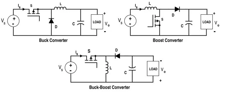
AC to DC converter (Rectifiers):
The AC to DC converter is also called a Rectifier. It converts AC (Alternating current) to DC (Direct current). Usually it is a step-down transformer which reduces the input voltage to a lower voltage value. It converts the low voltage AC supply into DC supply. Rectifiers are highly useful in EVs & HEVs during regenerative braking to charge up the battery.
AC to AC converter:
These converters are used to convert AC of one form to another. They are used in stepless fan regulators. They are not of much importance in EVs & HEVs.
2. Inputs given:
V = 72 V kɸ = 0.7
`R_a`=0.5 Ω Duty cycle = 70%
I = 400 A Chopper Switching frequency= 400 Hz
Relation between the torque and speed of the motor is given by the equation `T=24.7+0.0051omega^2`
Since the duty cycle is 70%, we will calculate the effective voltage for the load.
`72*(70/100) = 50.4 V`
The angular speed of motor is given by the equation `omega =V/(kphi)-(R_a/(kphi)^2)*T`
Substituting the inputs given,
`implies omega = 50.4/0.7-(0.5/(0.7)^2*T)`
`implies omega = 72-1.02T`
`implies T = (72-omega)/1.02`
`implies T=70.58-0.98 omega` --------------- 1
The relation between the torque and angular speed is already given by the equation
`T=24.7+0.0051omega^2` --------------- 2
Equating the two equations, we get
`24.7+0.0051omega^2=-0.98omega+70.58`
Further, re-arranging the terms,
`implies 0.0051 omega^2+0.98 omega-45.88=0`
To get the roots of the quadratic equation, we use the given formula.
`(-0.98+- sqrt (0.98^2-(4*0.0051*-45.88)))/(2*0.0051)`
`implies (-0.98+- sqrt (0.9604+0.9359))/(0.0102)`
`implies (-0.98+- 1.38)/(0.0102)`
Since we cannot have a negative value for the angular speed, we ignore the negative root.
`implies omega = (-0.98+1.38)/0.0102`
`implies omega = 39.2` rad/s
3. The author in the given article discusses the DC brushless motors and Induction motors, their similarities, differences, the advantages with them and also their limitations. It can be briefed up as below.
DC brushless motors
DC brushless motors contain rotors which include two or more permanent magnets that generate a DC magnetic field. The magnetic field enters the stator core and interacts with currents flowing within the windings to produce a torque interaction between the rotor and the stator.
Induction motors
In Induction motors, the rotor has no magnets. It has stacked steel laminations with buried peripheral conductors.
Similarities between the DC Brushless and Induction motors:
- Stators for the 3-phase induction motor and the DC brushless motor are virtually identical. Both have three sets of “distributed windings” that are inserted within the stator core.
- Both motors use 3-phase modulating inverters for their working.
Advantages of DC brushless motors
- Torque performance is better compared with Induction motors.
- Much less rotor heat is generated and the rotor cooling is easier.
- Peak point efficiency is generally higher than Induction motors.
- Can also operate at unity power factor.
Disadvantages of DC brushless motors
- Brushless DC motors produce no starting torque when directly connected to fixed frequency utility power. They really need the aid of an inverter whose “phase” is maintained in step with the angular position of the rotor.
- As the machine size grows, the magnetic losses increase proportionately and part load efficiency drops.
Advantages of Induction motors
- Induction motors are directly compatible with conventional utility power ---- the main reason for their success.
- At light loads the inverter can reduce voltage such that magnetic losses are reduced and efficiency is maximized.
Disadvantages of Induction motors
- 3-phase induction motors cannot operate from DC; AC is a must. Inverter is required to power an induction machine from a battery or other DC source.
- Induction machines are more difficult to control. The control laws are more complex. Achieving stability over the entire torque-speed range and over temperature is more difficult with induction than with DC brushless.
RESULTS & CONCLUSION:
- Thus the various types of power converter circuits such as Inverters, Choppers & Rectifiers are studied.
- The steady state speed of the motor is calculated as 39.2 rad/s.
- The author finally concludes that DC brushless motors will likely continue to dominate in the hybrid and plug-in hybrid vehicles and Induction motors will likely maintain dominance for the high-performance pure electric vehicles.