Comparing different methods of Mid-surface extraction & meshing
AIM:
To compare the mid-surface and mesh generated by Skin option, Casting and Batch mesh option for the given CAD model and determine the best method among them.
OBJECTIVE:
The objective of this project is to learn & get familiarized with the different methods of mid-surface extraction and meshing and find out the best suitable method.
PROCESS:
- Perform geometry clean up and resolve geometry errors.
- Extract the mid-surface and mesh the mid-surface using the Skin option & manual meshing, using the Offset option & Batch meshing and using the Casting method.
- After the mid-surfacing is done, check for the preciseness of mid-surface and correct missed feature capturing in the mid-surface.
- After the meshing is done, resolve the quality issues and obtain a better mesh flow.
SOFTWARE USED:
ANSA (Automatic Net generation for Structural Analysis) v19.0.1 64-bit
PERFORM GEOMETRY CLEAN UP:
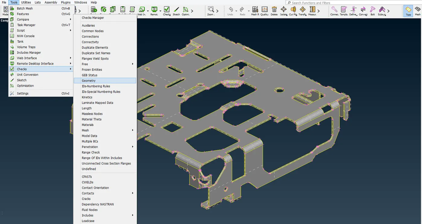
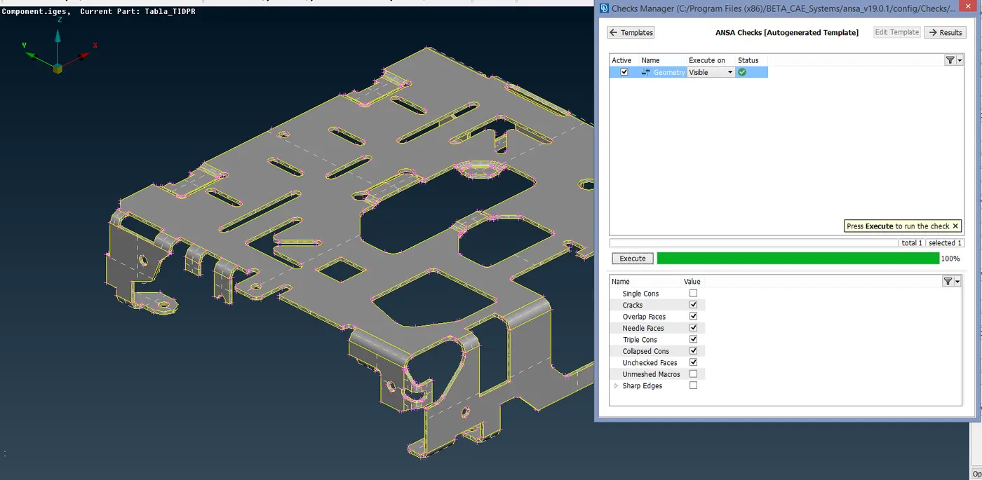
The Geometry check can be seen under the TOOLS tab under CHECKS -> GEOMETRY. The Geometry clean up can also be done through the CHECKS command.
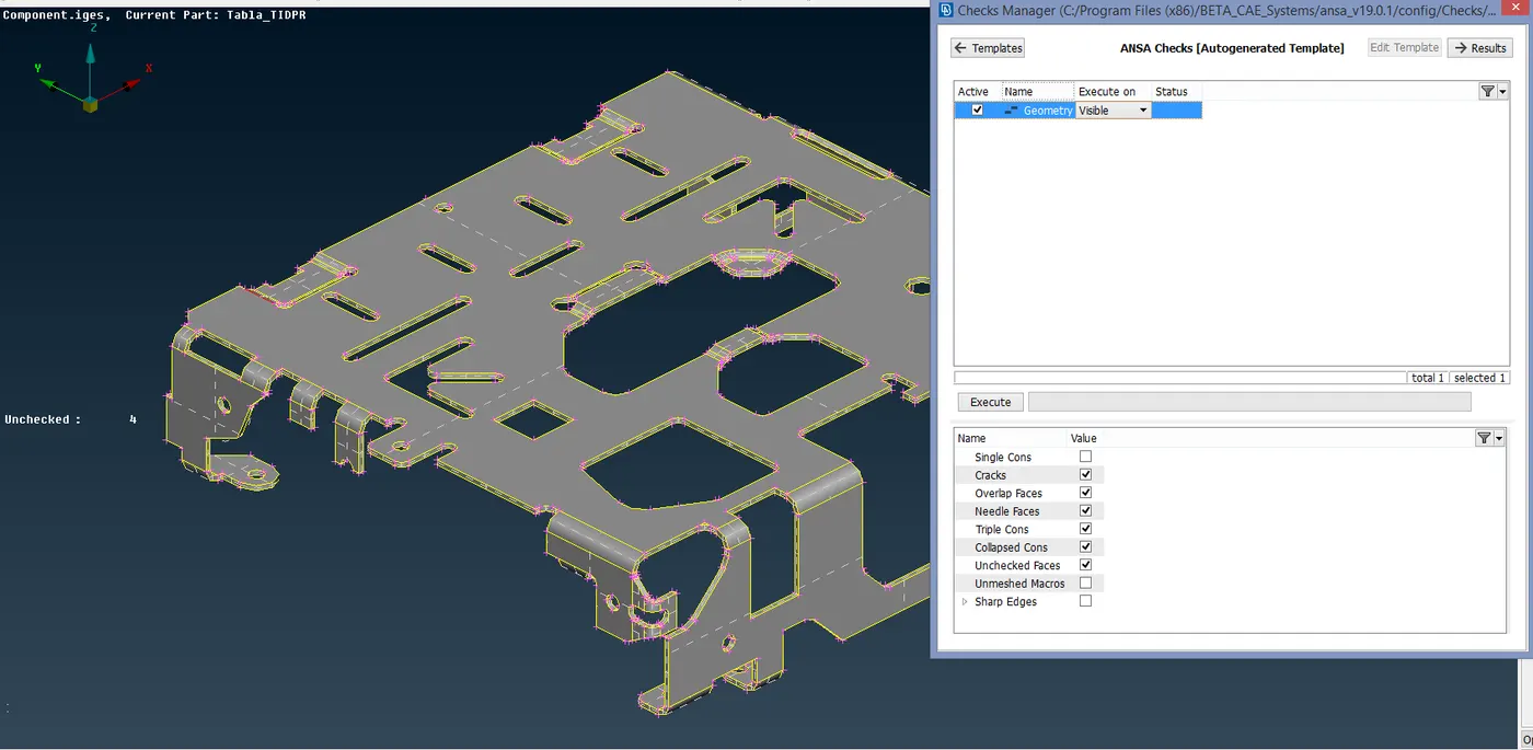
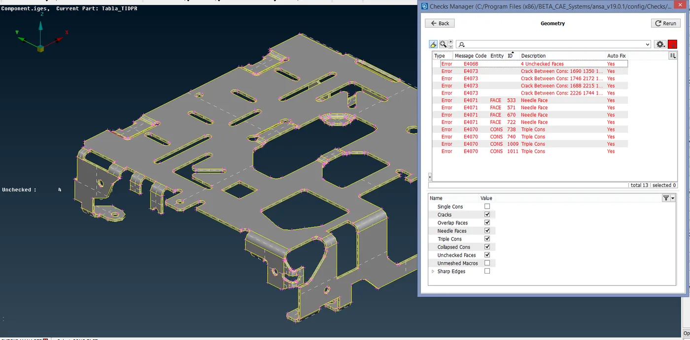
On clicking the EXECUTE button, the errors or geometrical issues in the model will pop up.
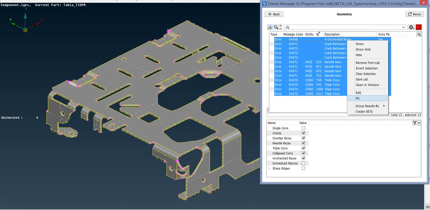
These errors can be fixed manually one by one or can be fixed automatically. When fixing automatically, the errors are fixed by ANSA.
Once the errors are fixed, the geometry checks should be run again. It should be ensured that there are no geometry issues.
MIDSURFACE EXTRACTION:
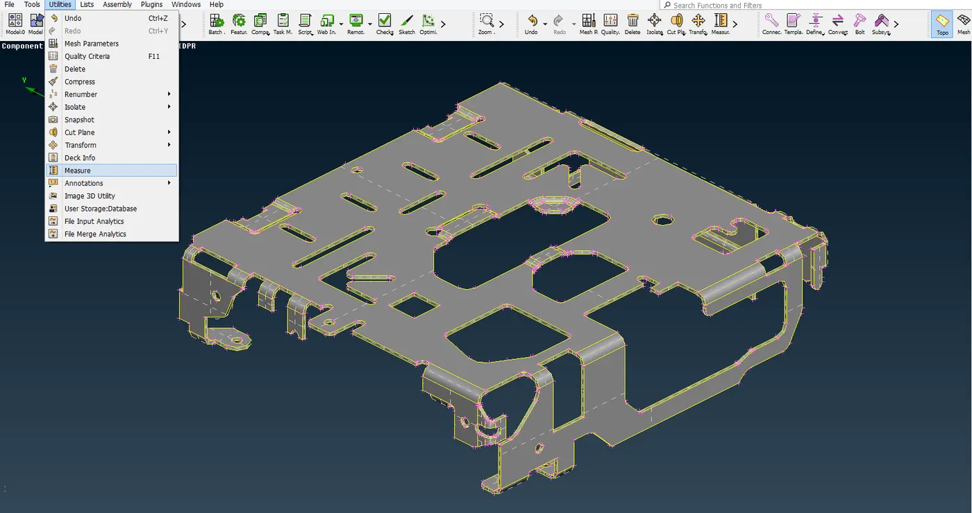
Before extracting the mid-surface for the component, the thickness of each of the surfaces needs to be known. The thickness of the surfaces can be measured using the MEASURE command, which is under the UTILITIES tab.
By selecting the CONS/Curves option, the distance between two CONS or Curves can be measured and the thickness value is stored. By selecting the Nodes option, the distance between two nodes can be measured.
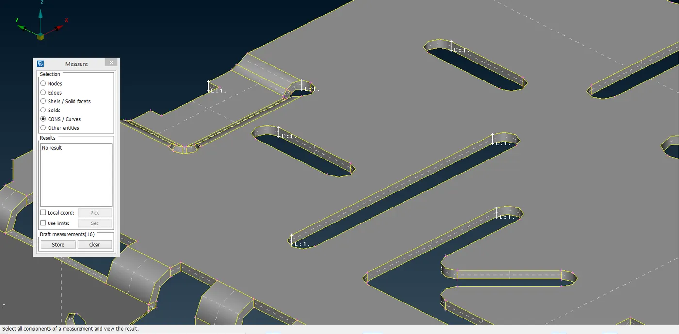
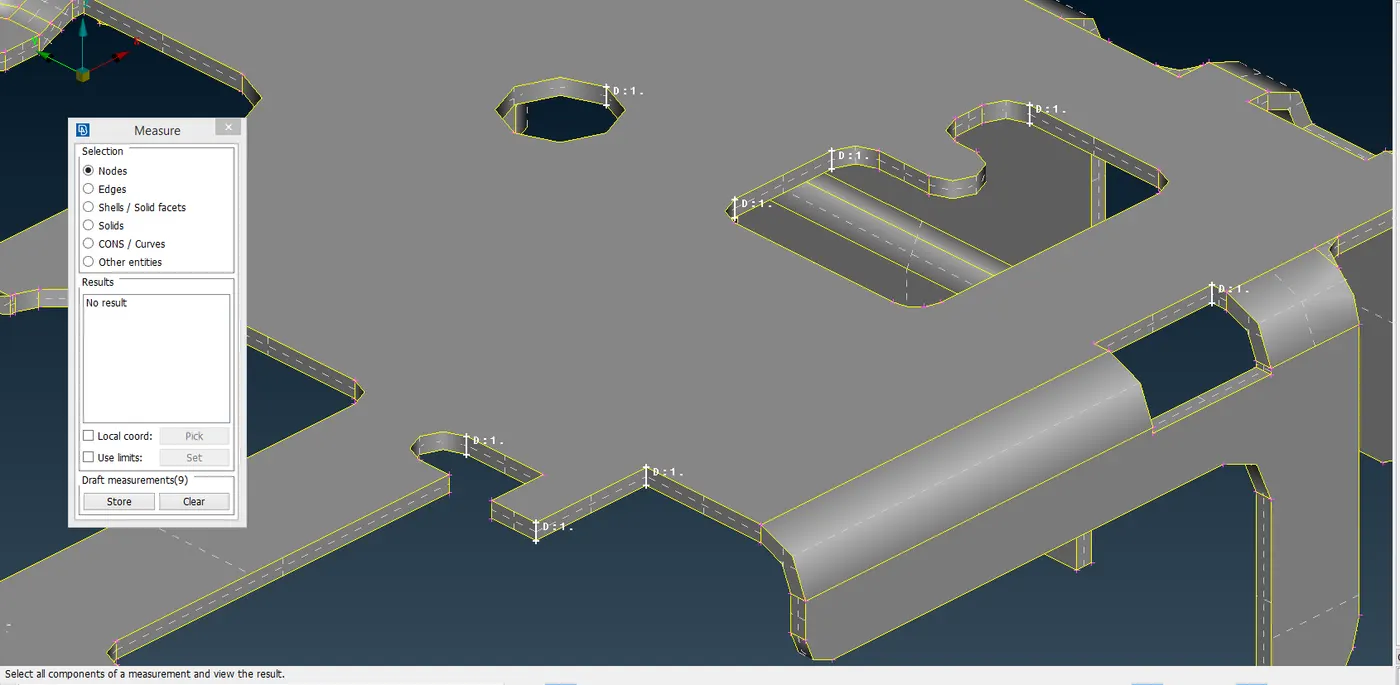
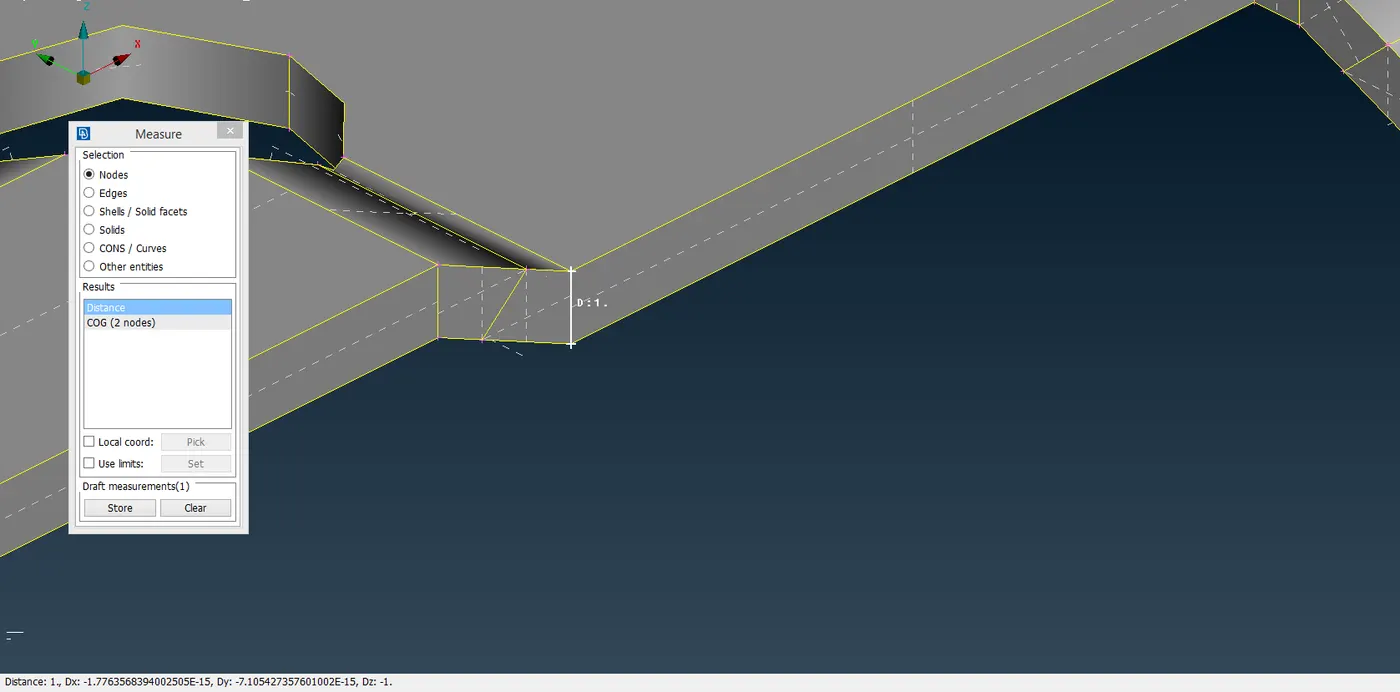
Now it can be seen that the thickness of this component is uniform.
SKIN OPTION:
In this method, the mid-surface is generated by the ANSA software automatically as soon as the CAD model is selected. The SKIN option is in the TOPO module under the FACES -> MID. SURFACE module button.
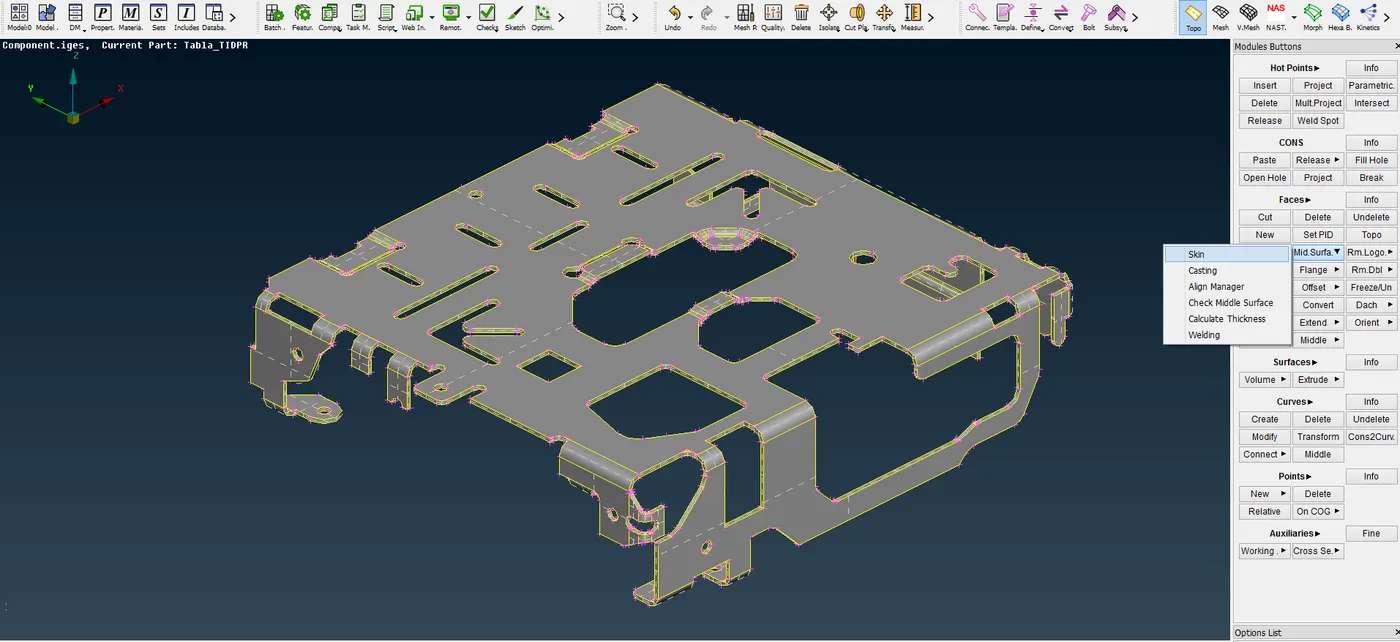
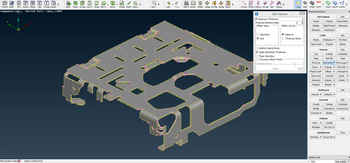
The maximum thickness of the CAD model and the thickness decimal digits are given and the component is box selected.
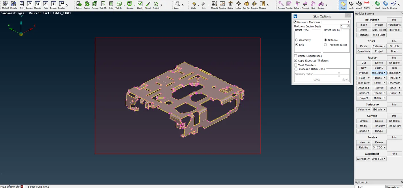
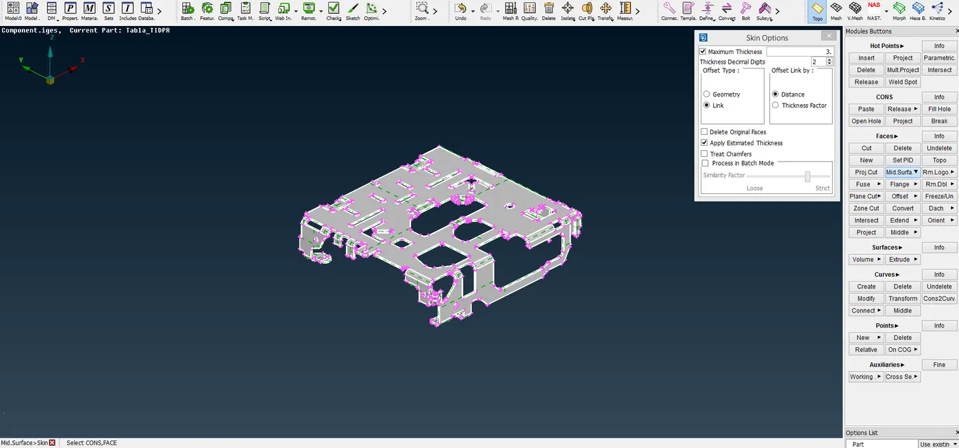
Upon accepting, the CAD model is highlighted with green, blue and red colour.
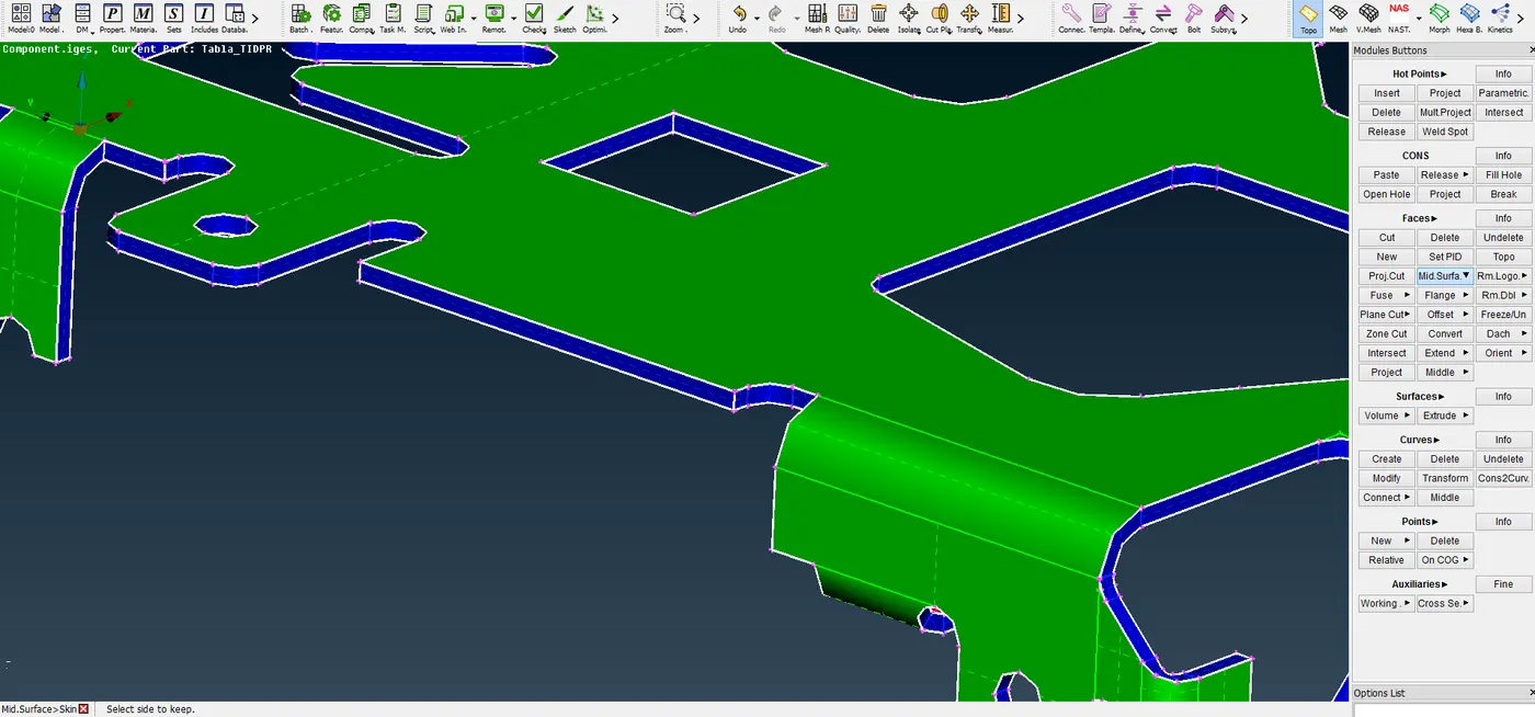
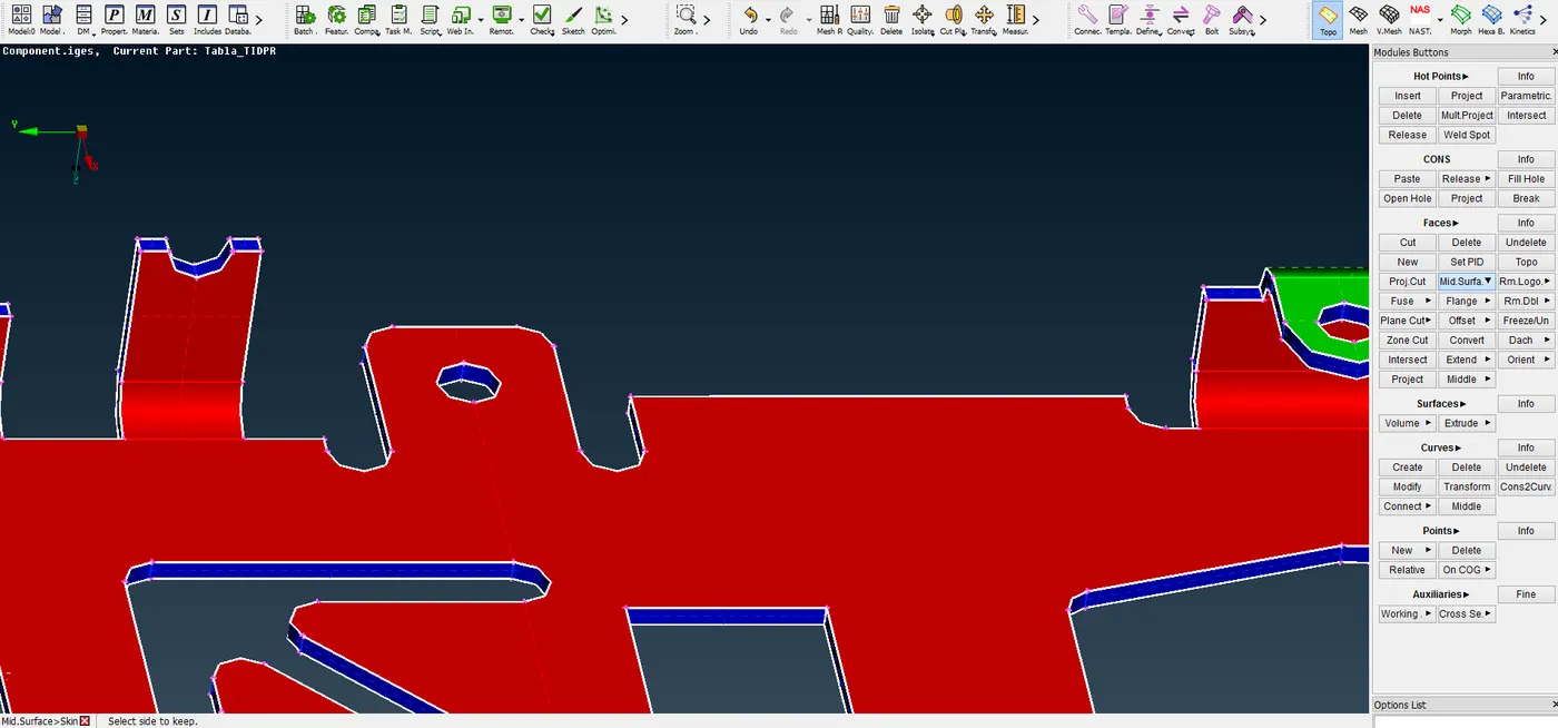
The green colour denotes the outer surface of the component and the red colour denotes the inner side of the component. The blue colour denotes the thickness of the component.
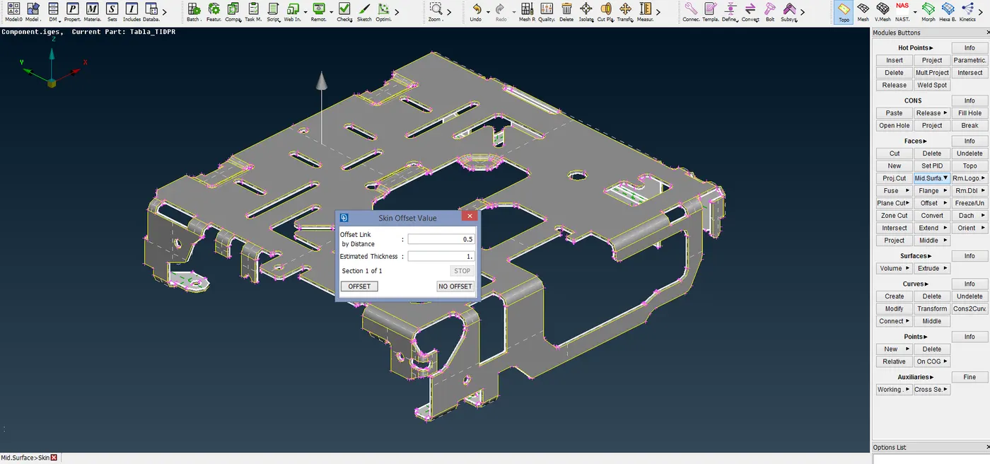
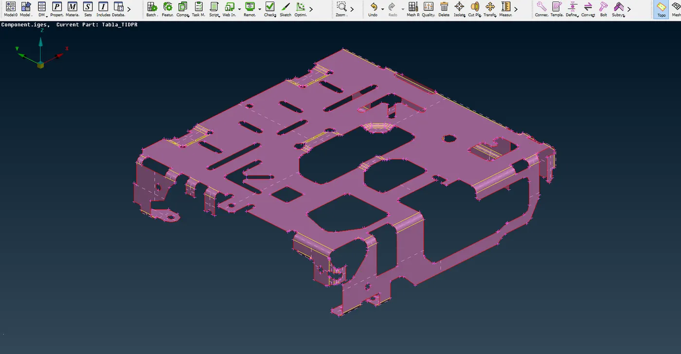
On clicking the OFFSET button, the mid-surface is generated and it is assigned with a separate Property ID.
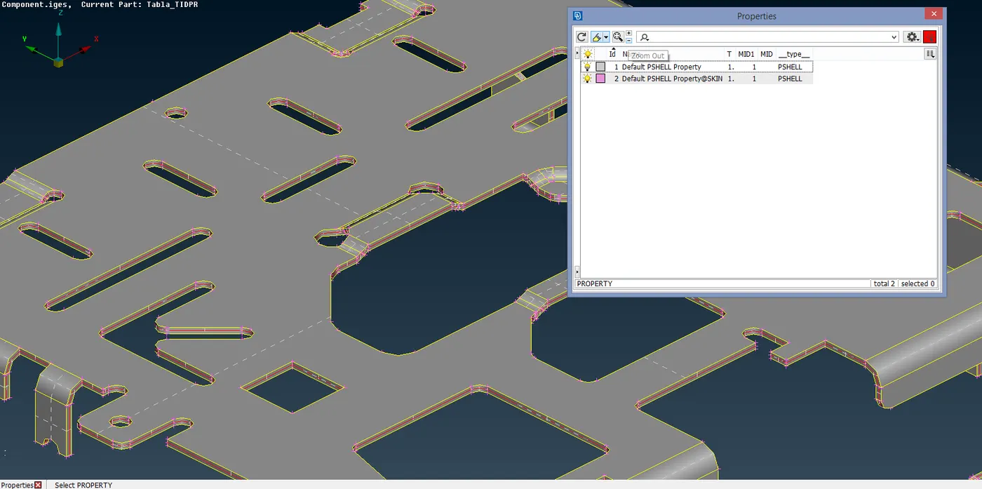
The Property ID and the mid-surface can be seen in the PROPERTIES dialog box which is under the LISTS tab. There is also a shortcut for the PROPERTIES dialog box. It is CTLR + P.
OFFSET METHOD:
This is the manual offset method where each of the faces of the CAD model are selected and offset to the required distance.
The OFFSET command is in the TOPO module under the FACES -> OFFSET button.
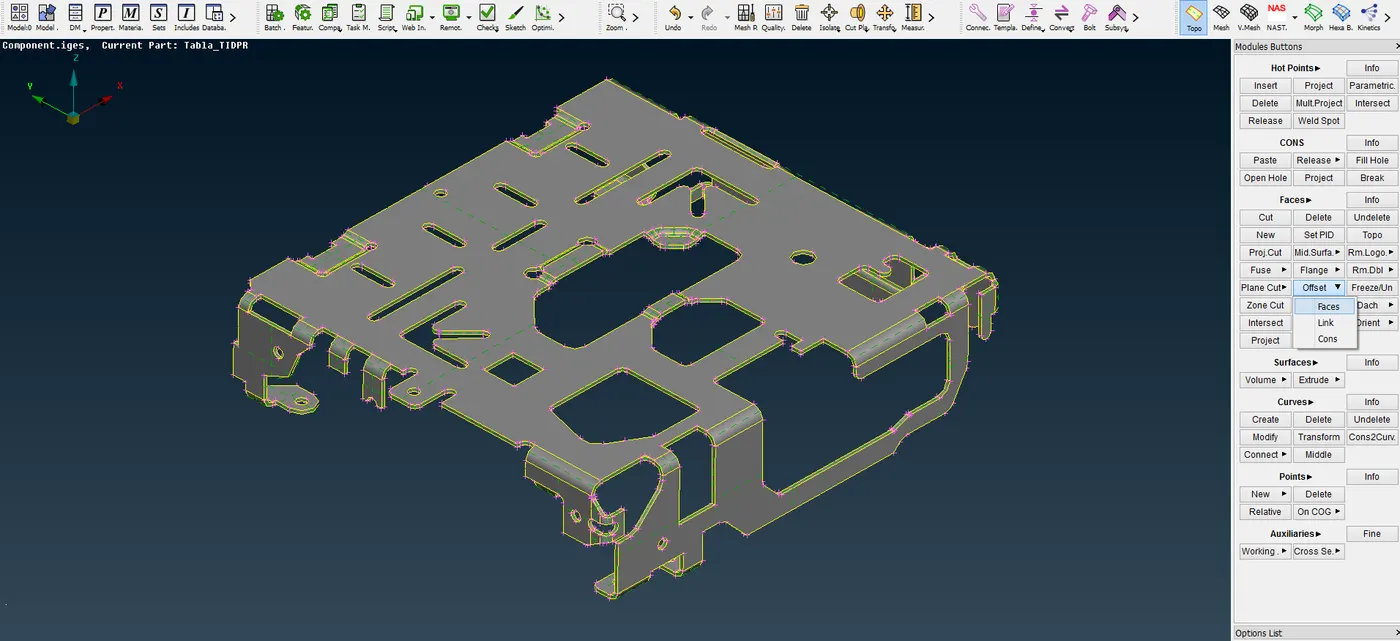
The surface is selected and after accepting, the distance to offset is entered. Then the surface is offset to the given distance.
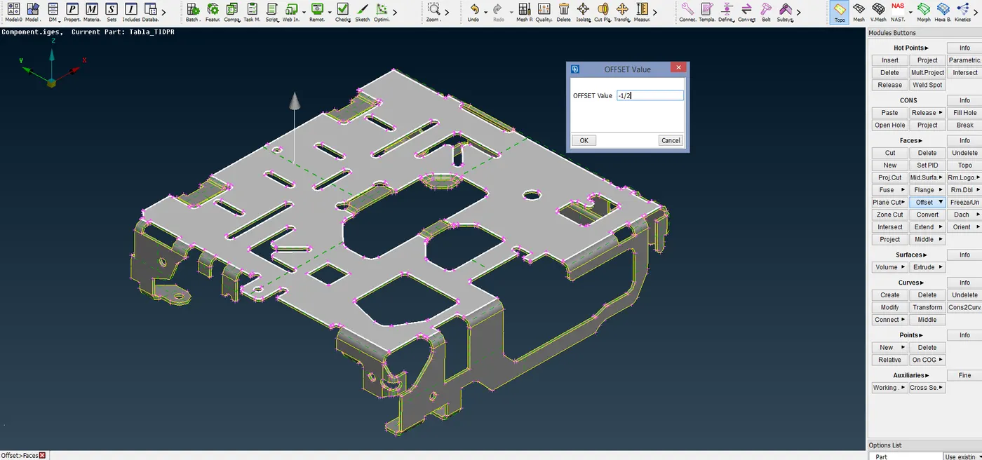
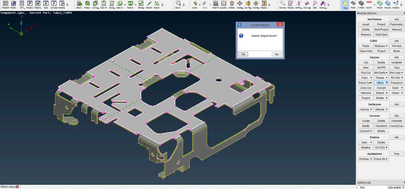
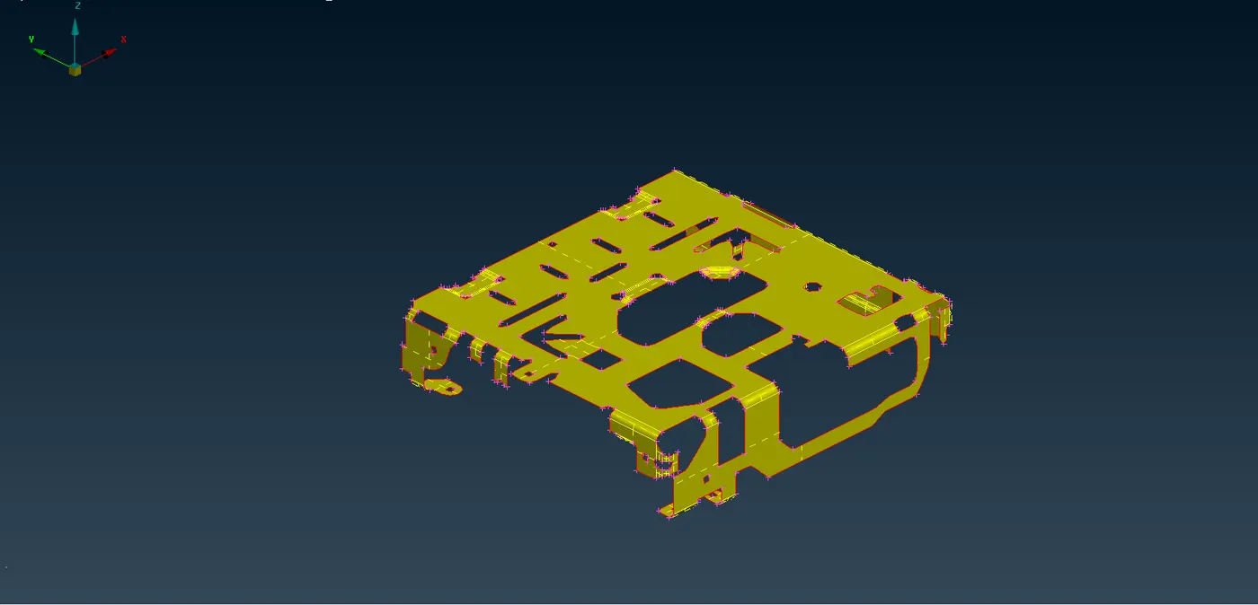
This way the mid-surface is generated for all the surfaces one by one. The mid-surface can also be generated for the whole CAD model at once. This is done by selecting the FEATURE AREA selection.
This way the mid-surface is generated using the OFFSET method.
CHECKING PRECISENESS OF THE MID-SURFACE & CORRECT MISSED FEATURE CAPTURING:
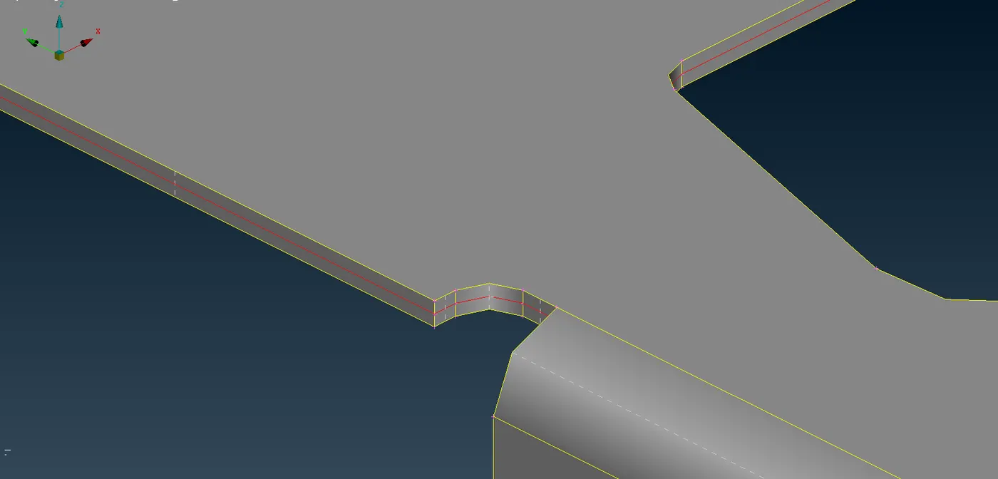
After the mid-surface is generated, the preciseness of the mid-surface is checked by putting the parent surface in Transparency in the PID mode.
SKIN OPTION:
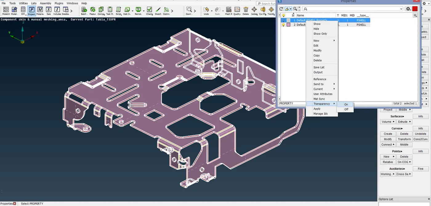
After the transparency is turned ON, both the parent and the mid-surface are visible. This is used to check how correct the mid-surface is in accordance with the parent surface.
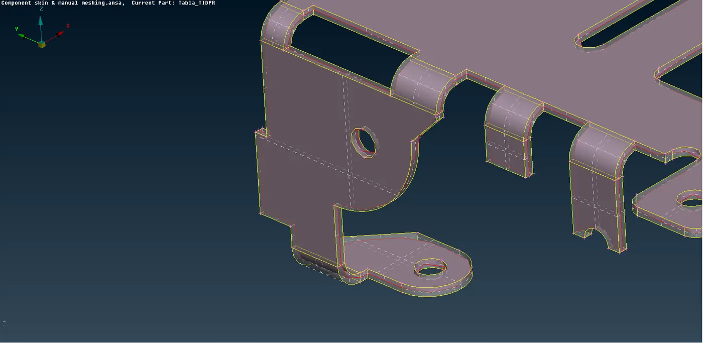
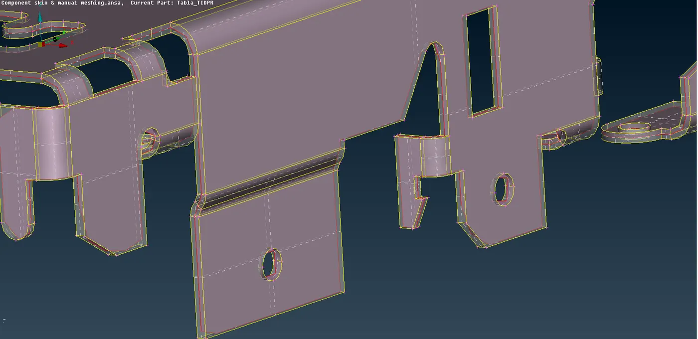
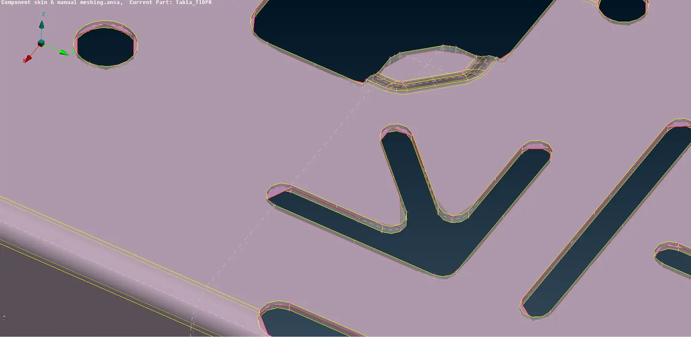
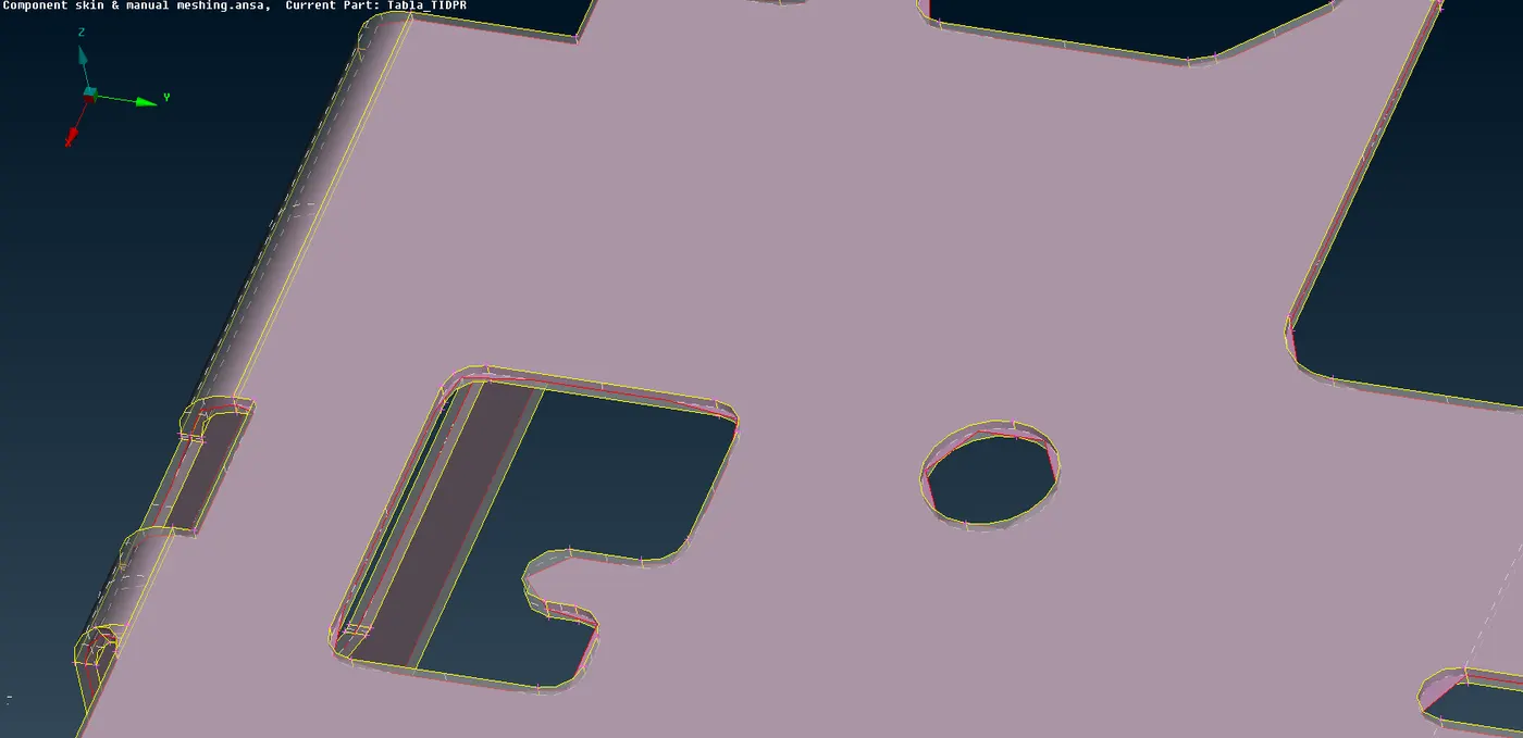
If there are any discrepancies available in the mid-surface like the mid-surface coming out of the parent surface or the going inside the parent surface, this means that the mid-surface needs to be corrected.
OFFSET METHOD:
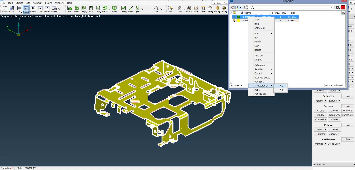
Similarly for the offset method, the mid-surface is compared with the parent surface with the transparency turned ON.
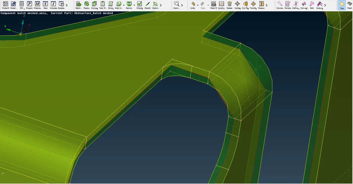
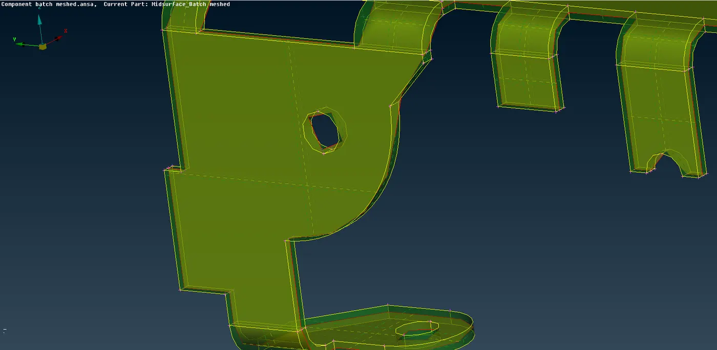
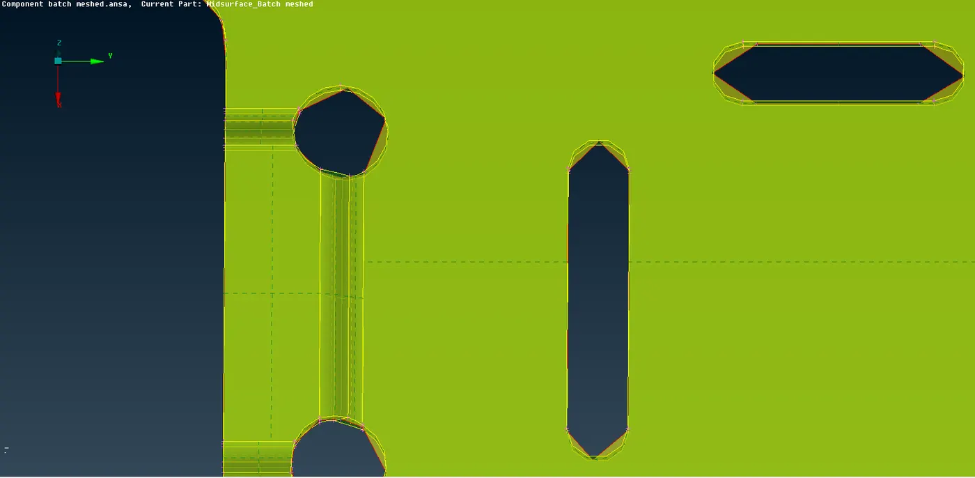
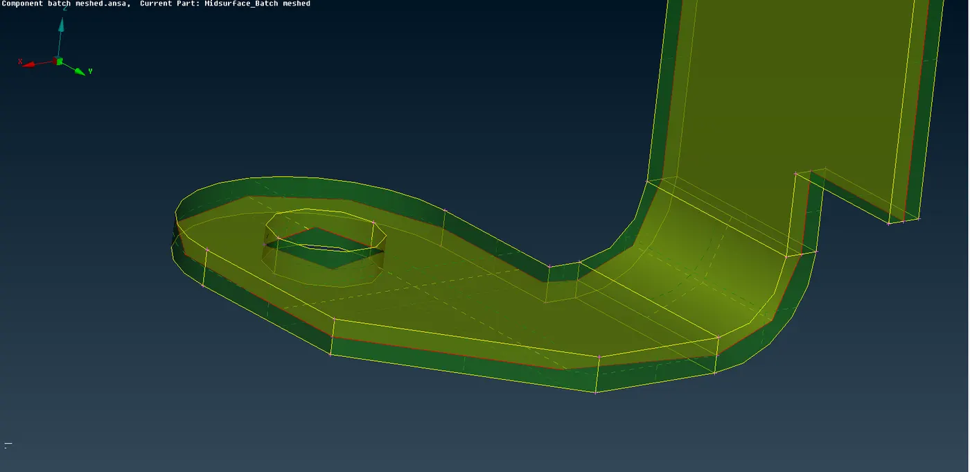
Next, the Feature capturing needs to be checked. Features like fillets, holes, chamfers etc. may be missed or ignored while extracting the mid-surface or during meshing. They should be checked and if missing need to be corrected.
In the SKIN option method, the Feature capturing needs to be checked before meshing.
In the OFFSET method, the Feature capturing needs to be checked after the Batch meshing because the construction lines are re-arranged by ANSA when the Batch meshing process is in progress.
MESHING:
MANUAL MESHING:
In Manual meshing, the meshing is done with the help of SPOT MESH and BEST MESH meshing algorithms.
The surface is split into separate macros using the MACROS -> CUT command and is meshed. The reason of splitting the surfaces into small rectangle or square shaped macros is to obtain better mesh flow.
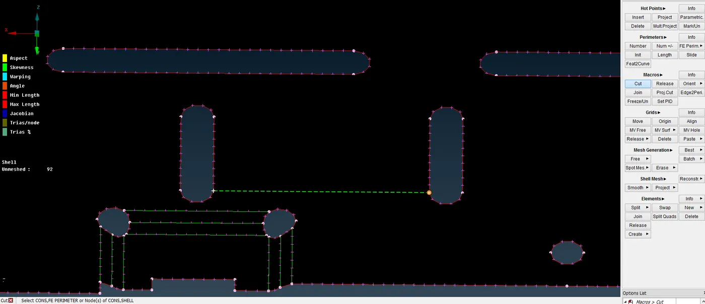
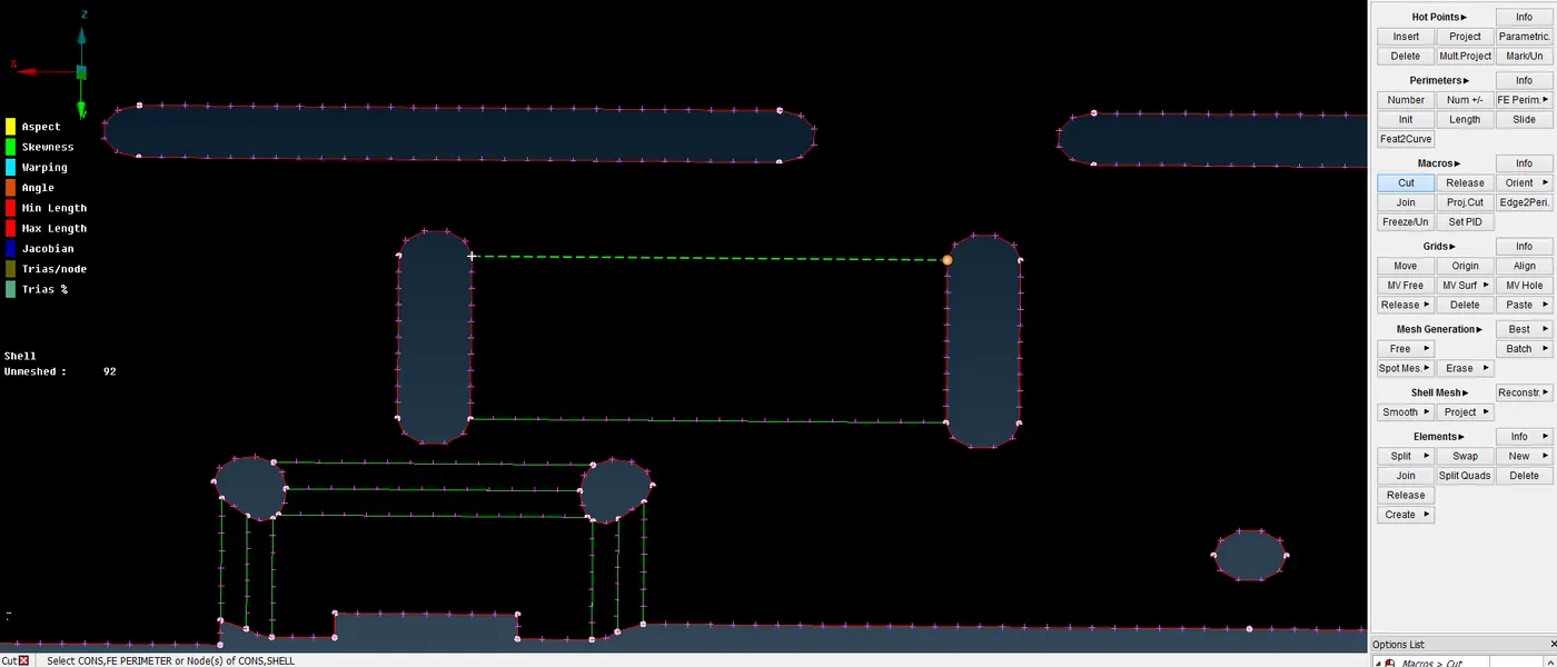
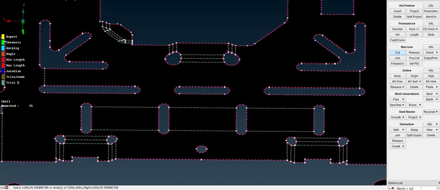
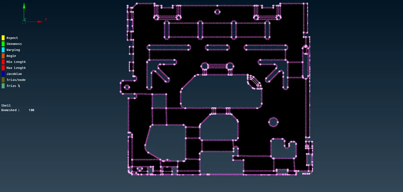
Once the meshing is done, the macros are joined using the JOIN command which is under the MACROS module button.
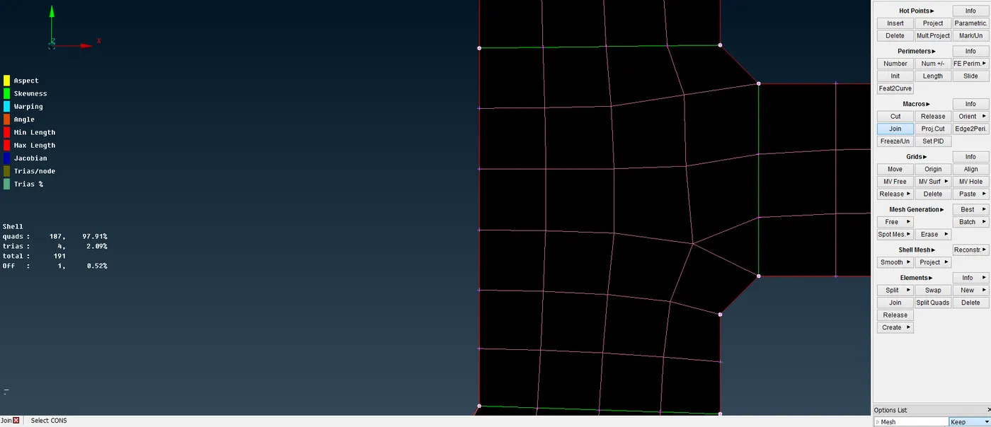
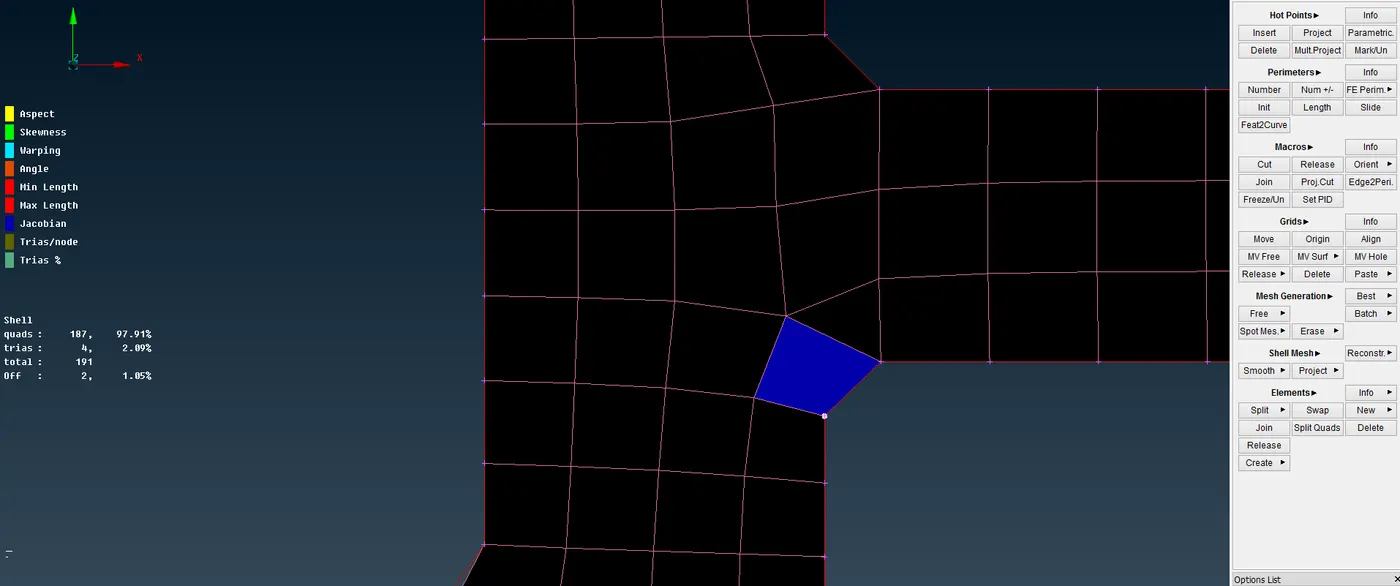
BATCH MESHING:
Batch meshing is a meshing process where the re-arranging of construction lines and meshing is done by built-in algorithms in ANSA.
Before the Batch meshing is done, the mid-surface extracted needs to be set in as a separate Part. The mid-surface is set as a separate part using the MODEL BROWSER. It is under the LISTS tab.
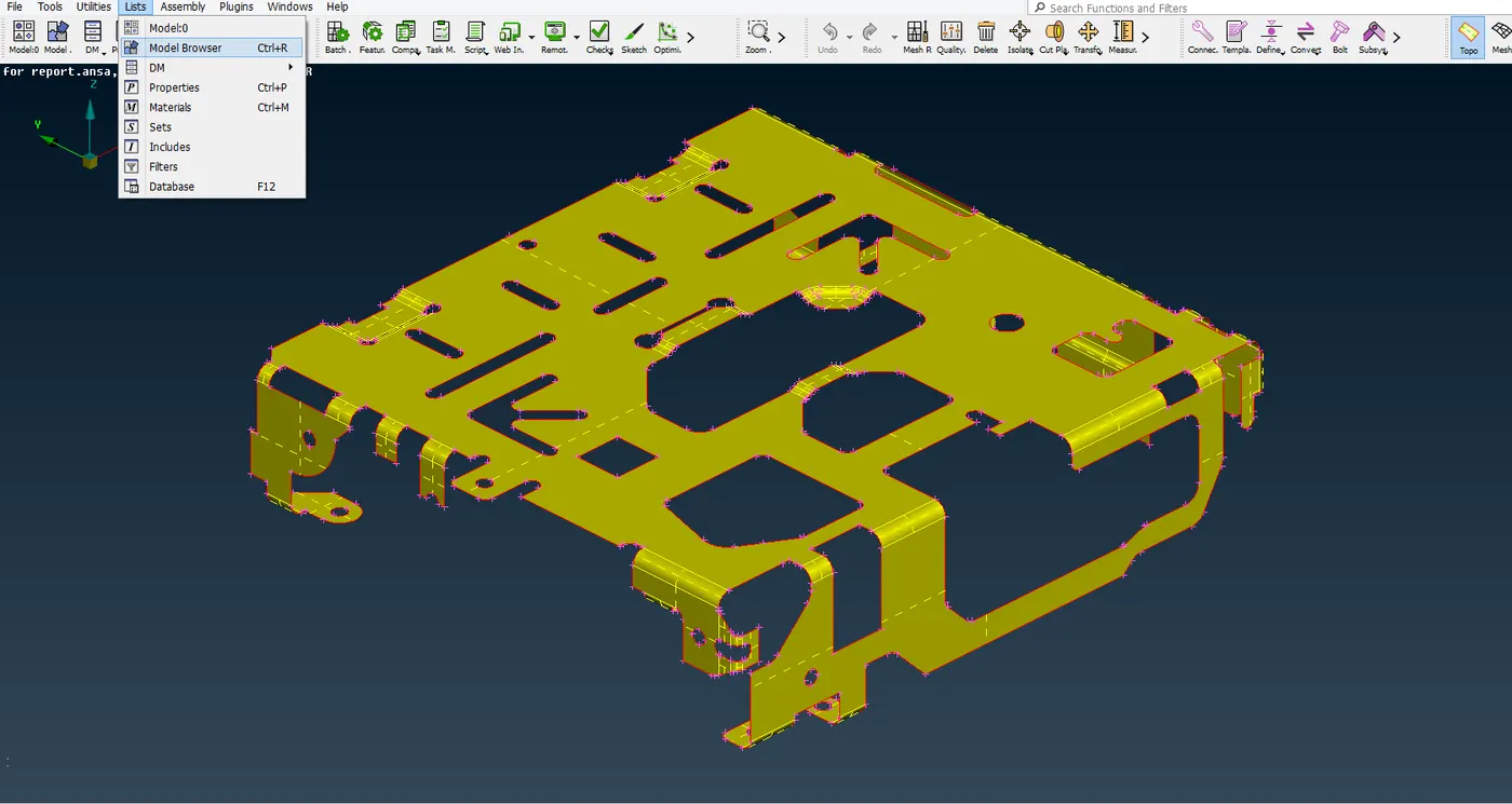
Then the Set part button is clicked, and the mid-surface is selected with a box selection.
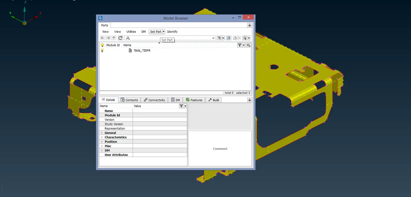
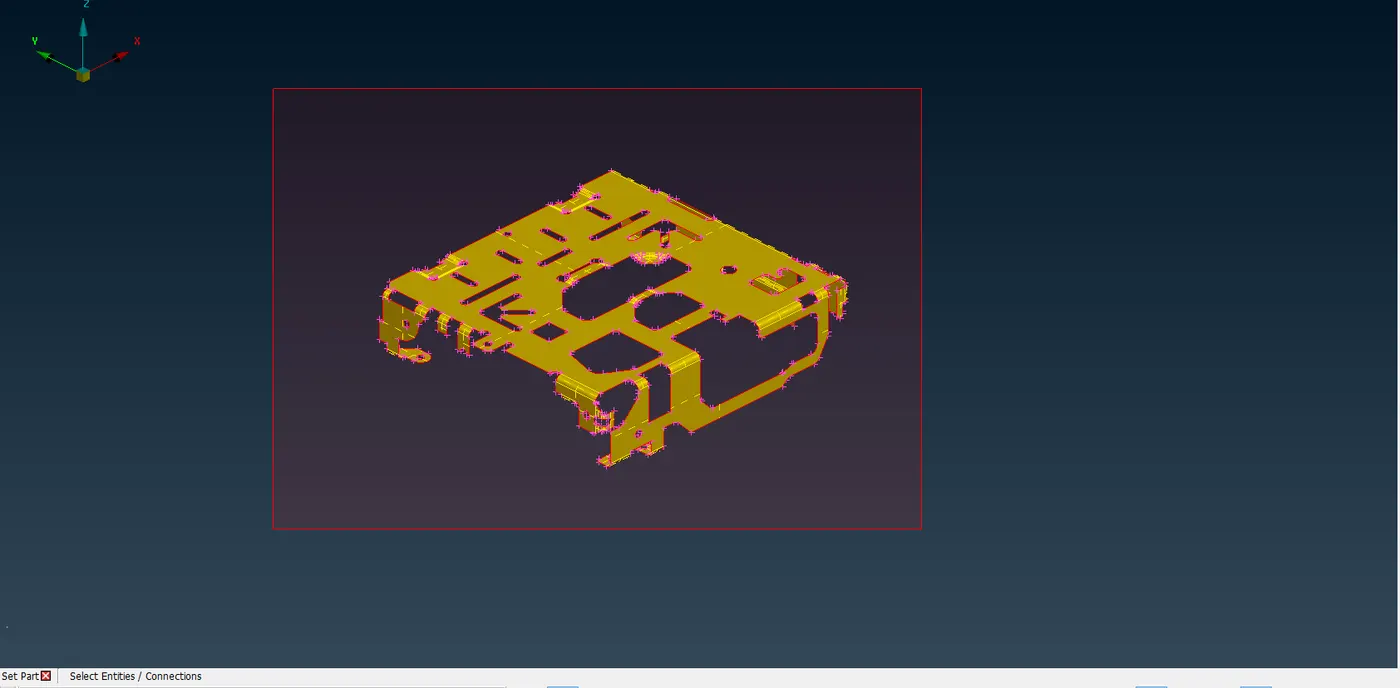
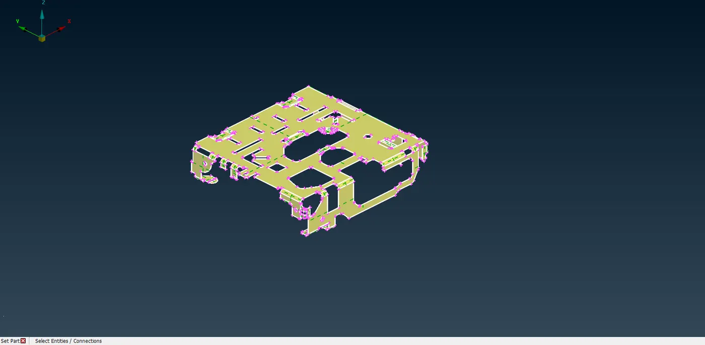
Upon accepting, a new part is created. With a middle-mouse click, the mid-surface is assigned to the part.
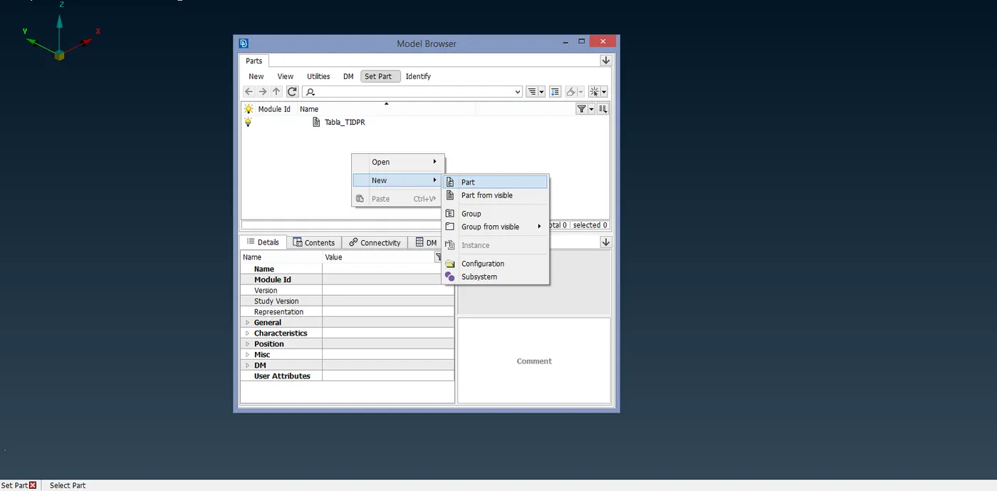
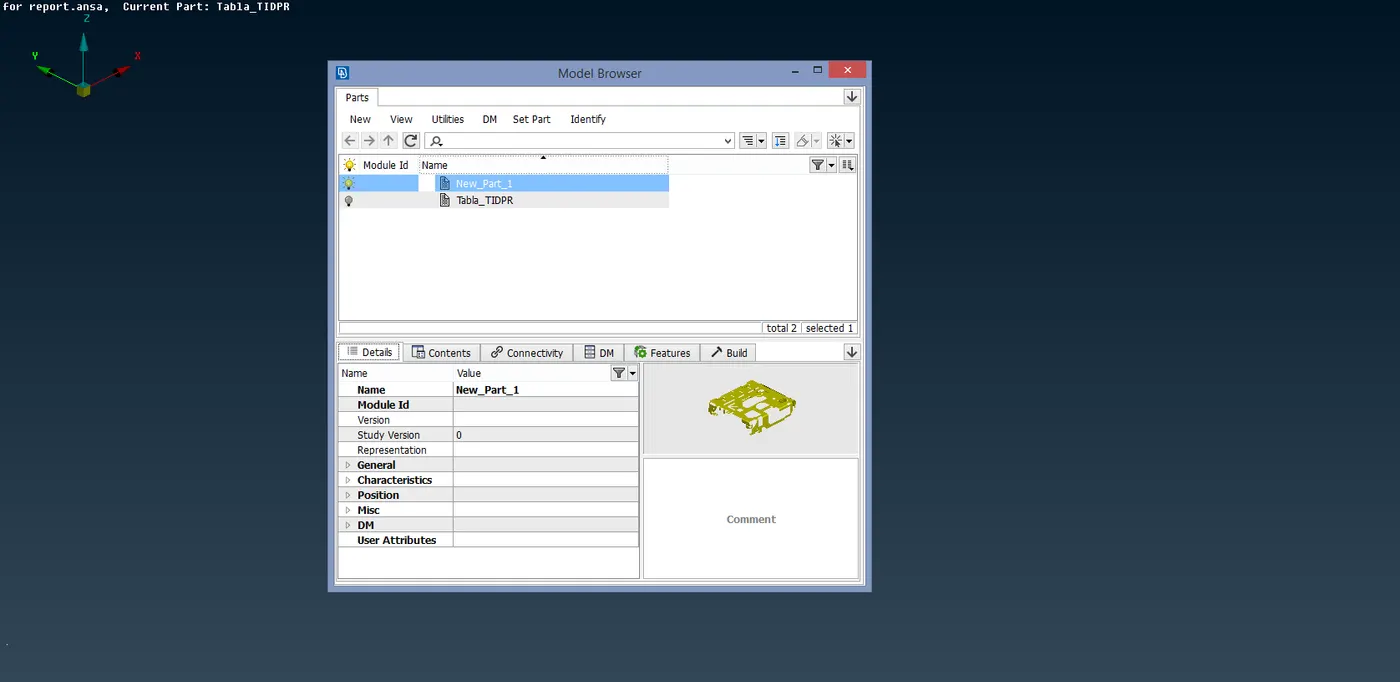
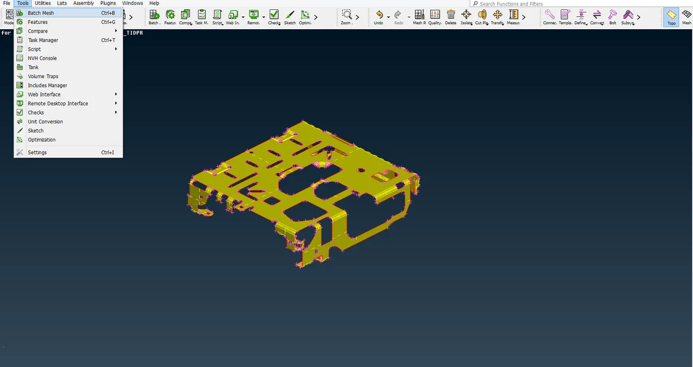
Now, the meshing needs to be done. The BATCH MESHING command is under the TOOLS tab. In the BATCH MESH MANAGER, a new Meshing scenario needs to be created. It is under the NEW button.
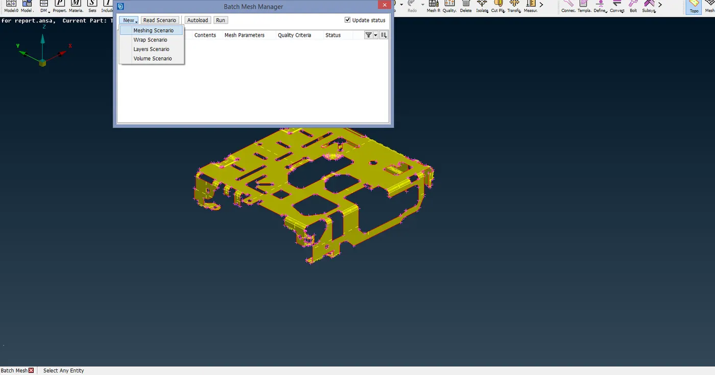
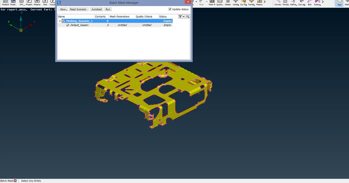
After the Meshing scenario is created, the mid-surface needs to be selected. It is selected by double-clicking under the CONTENTS tab.
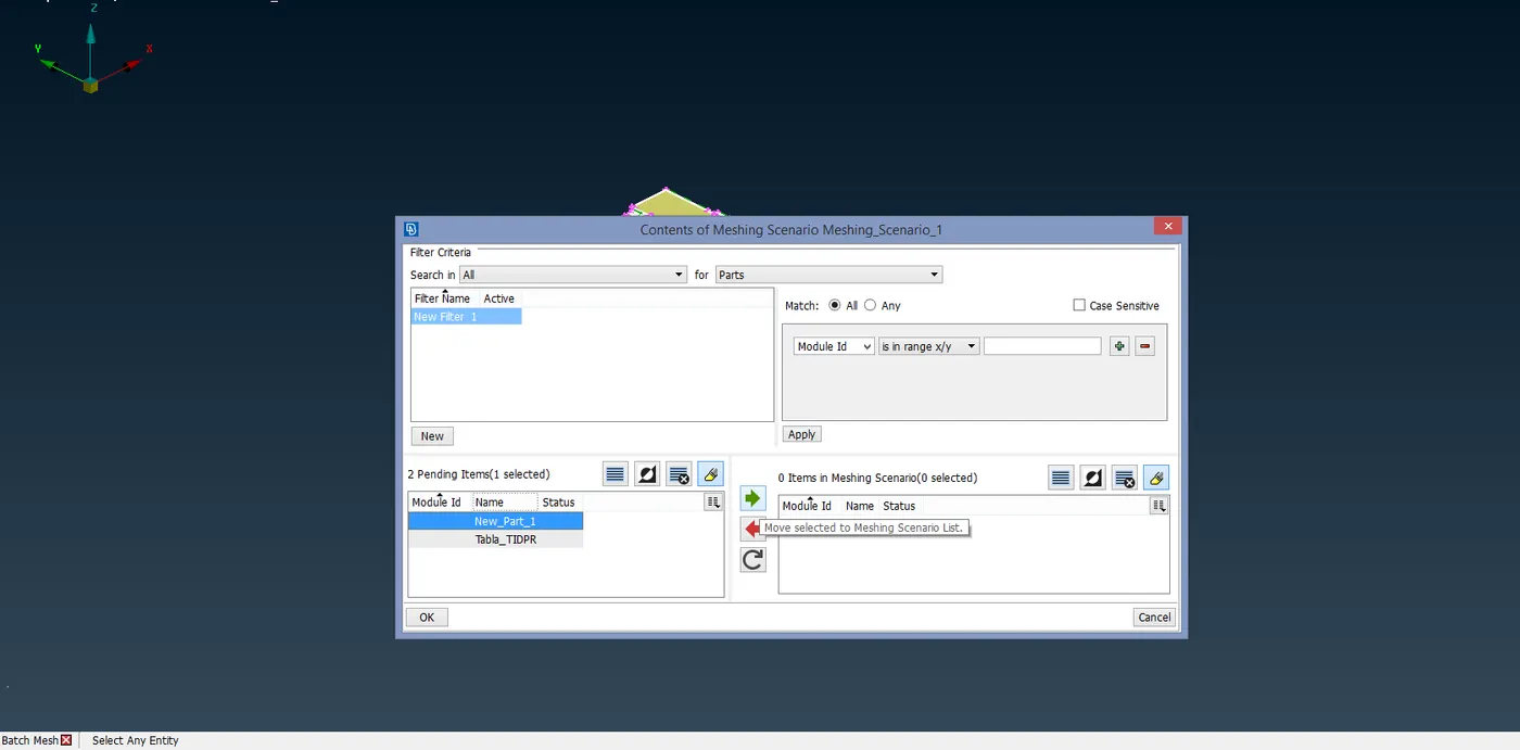
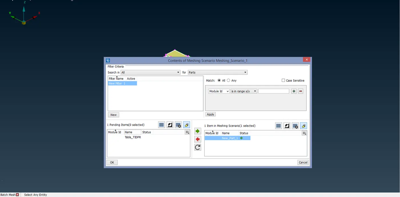
In the Contents tab, the Part is selected.
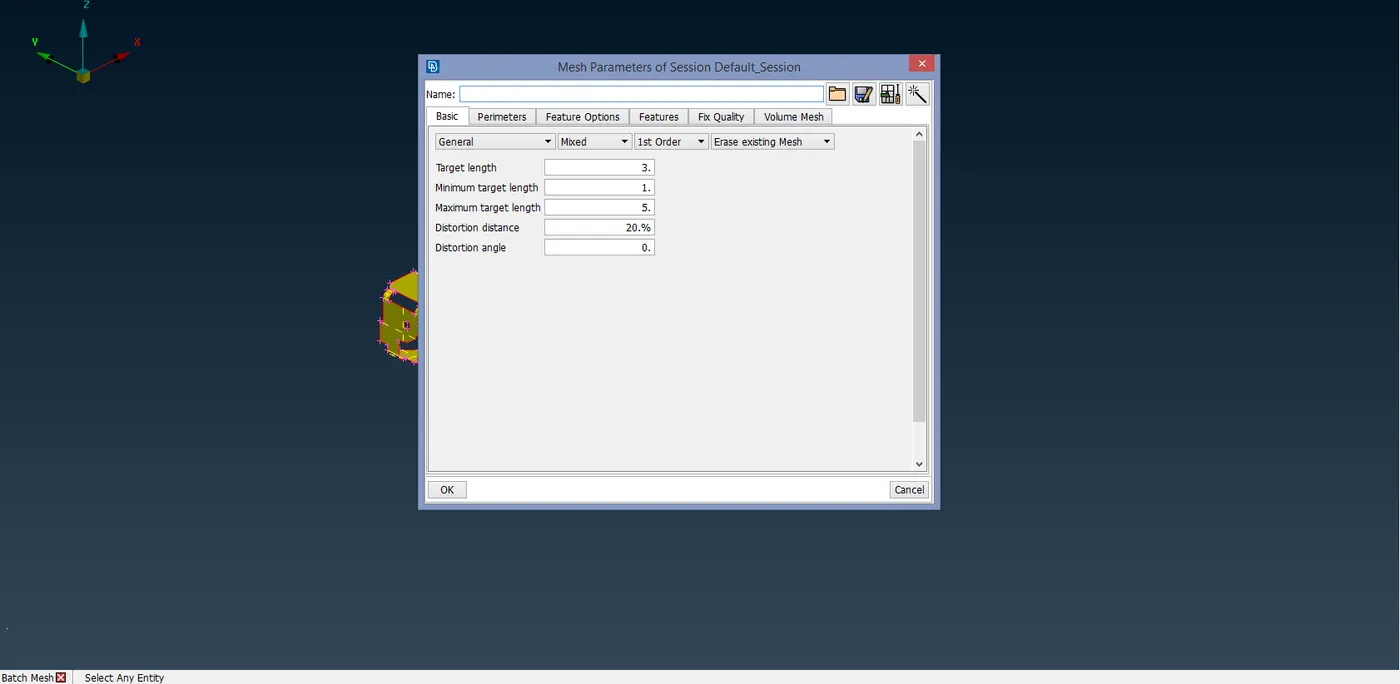
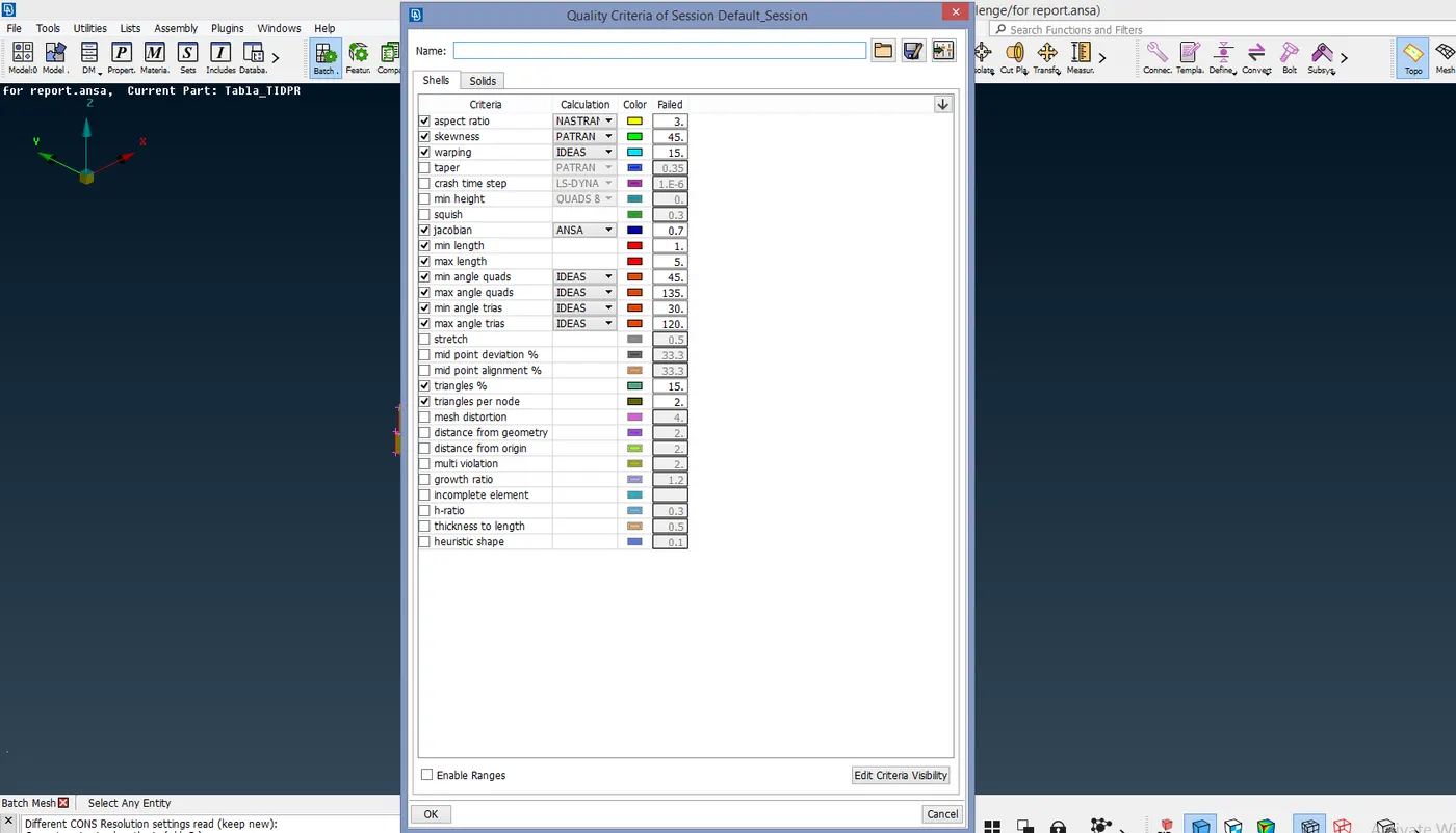
The Mesh parameters and Quality criteria are assigned by double-clicking under the Mesh parameters and Quality criteria tab.
Then, the RUN command is given and the algorithm is applied.
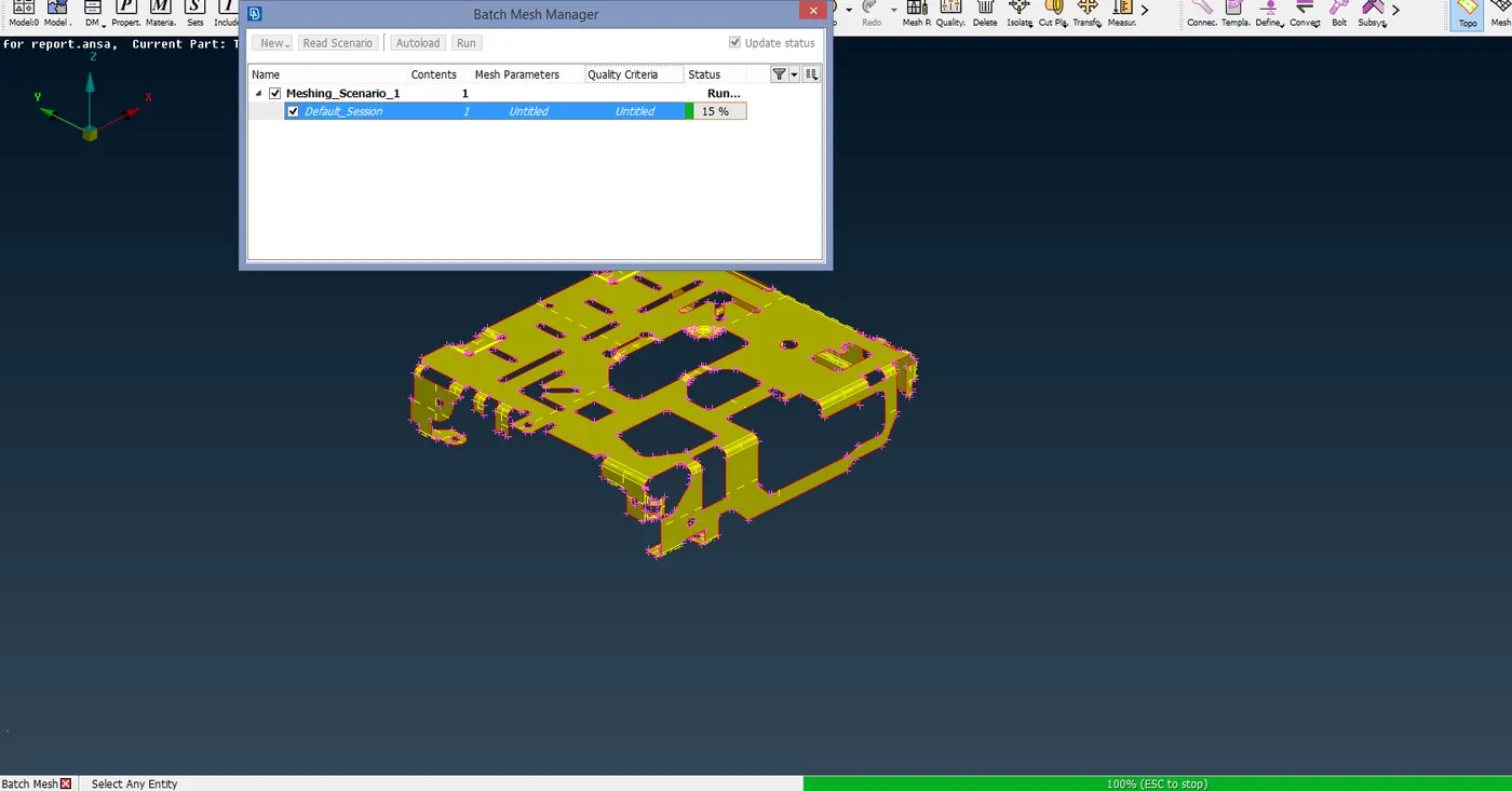
Finally, the re-arrangement of construction lines is done and the mid-surface is meshed.
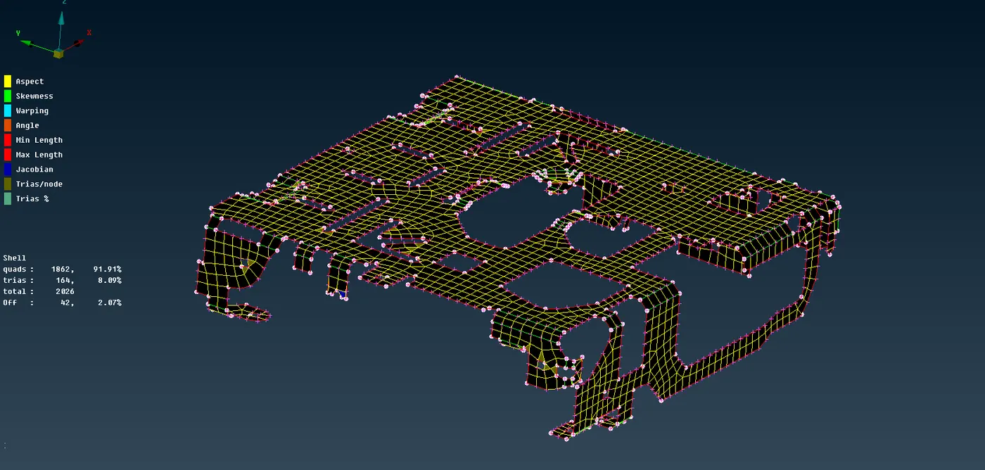
Once the meshing is done, the mid-surface needs to be checked for the preciseness and feature capturing.
Now, it can be seen that some of the construction lines have been disabled in the mid-surface (orange colour). We need to check with the parent surface for the feature capturing. If disabling the construction line affects a feature such as a fillet, that line needs to be enabled.
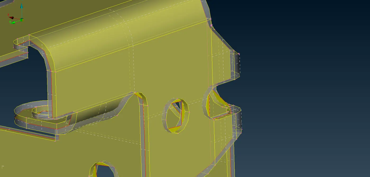
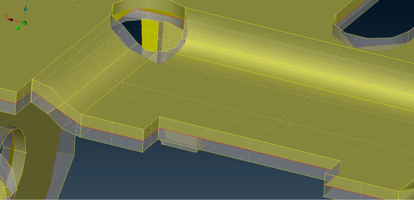
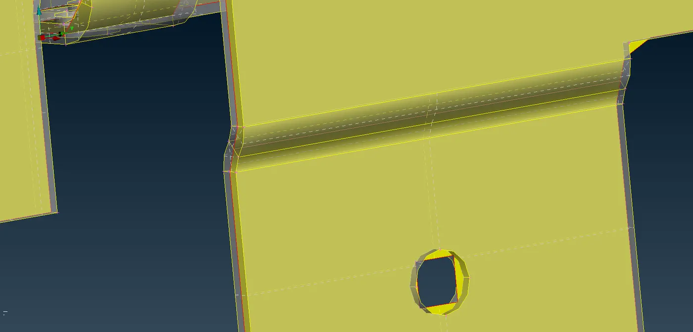
Here we can that see that without the construction line, the fillet is not captured and with the construction line the fillet will be better captured.
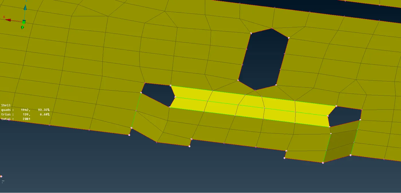
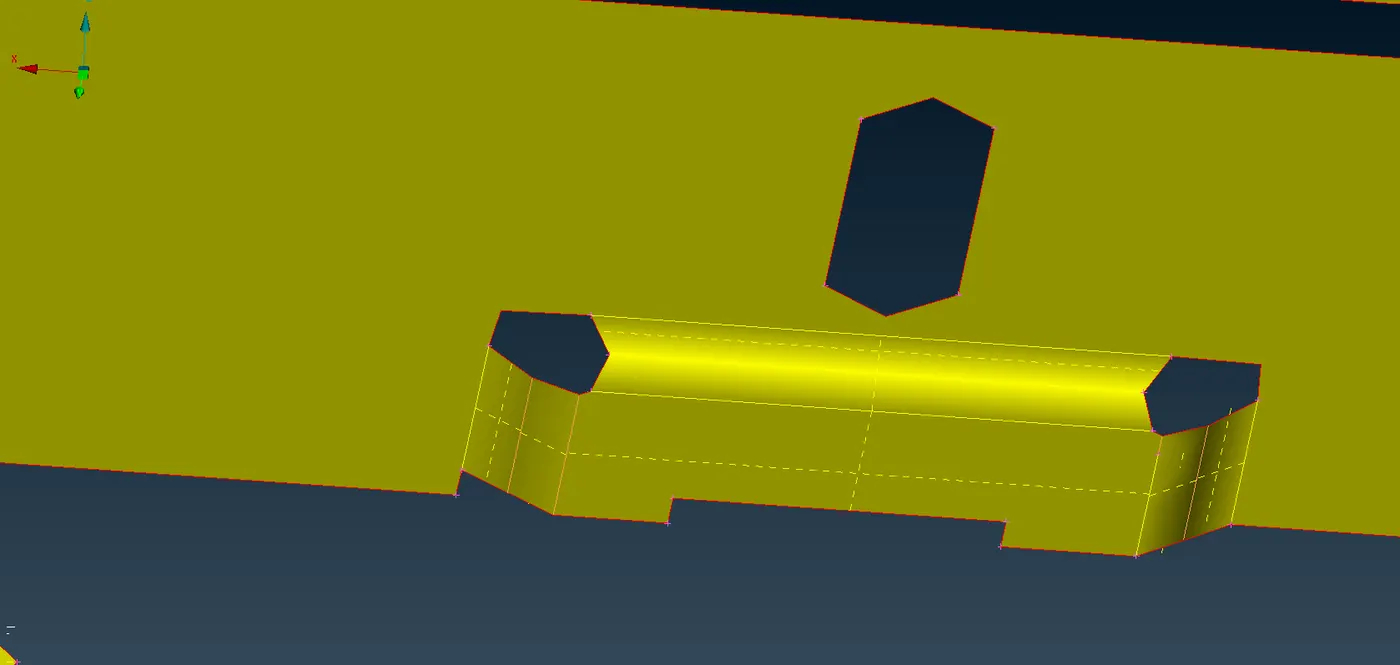
By enabling the construction line, the feature will be captured. Also the mesh in that particular macro area will be erased by enabling the construction line. So, before enabling the construction line, we need to prevent the mesh from getting erased.
This can be done by using the EDGE2PERIMETER command. It is under the MACROS module button in the MESH mode.
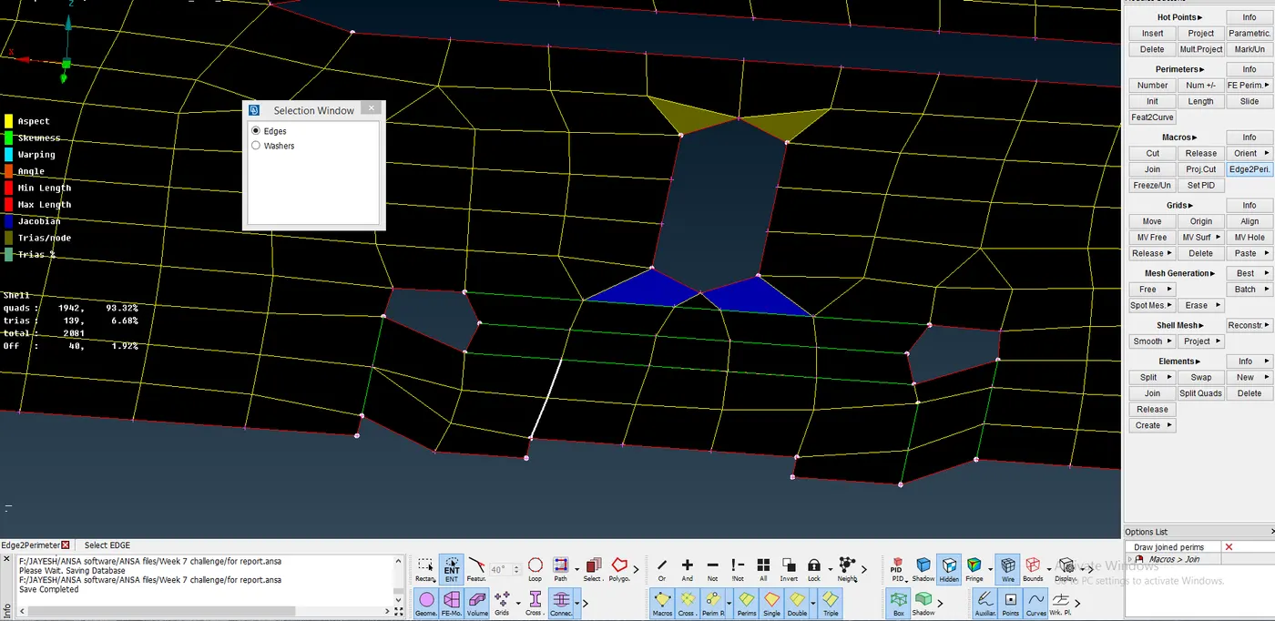
By enabling the command, select the edges of the mesh elements (FE) and accept. This way a macro area is created with the edges of the mesh elements.
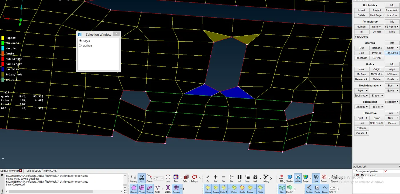
The construction line is enabled using the RELEASE command which is under the MACROS module button in the MESH mode.
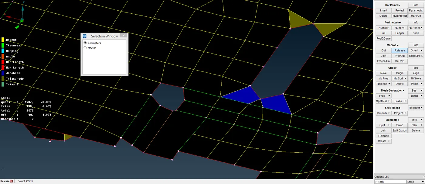
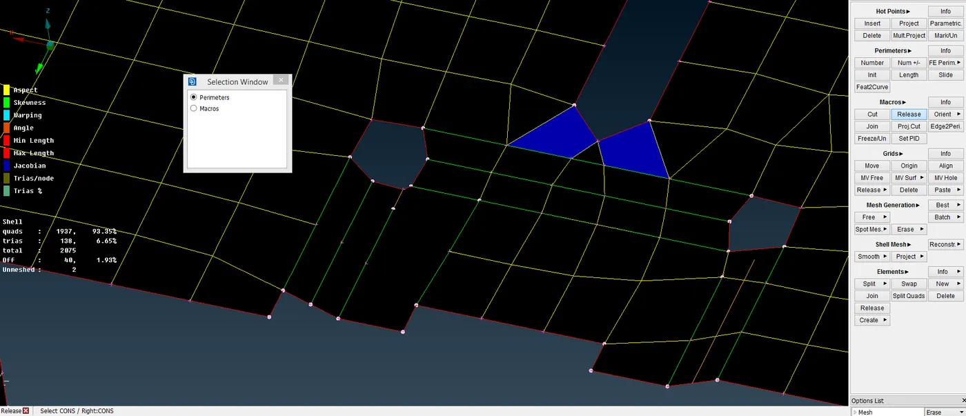
Now when the construction line is enabled, the mesh within the small macro area alone will be erased. This area can be re-meshed using the SPOT MESH command which is
under the MESH GENERATION command button in the MESH mode.
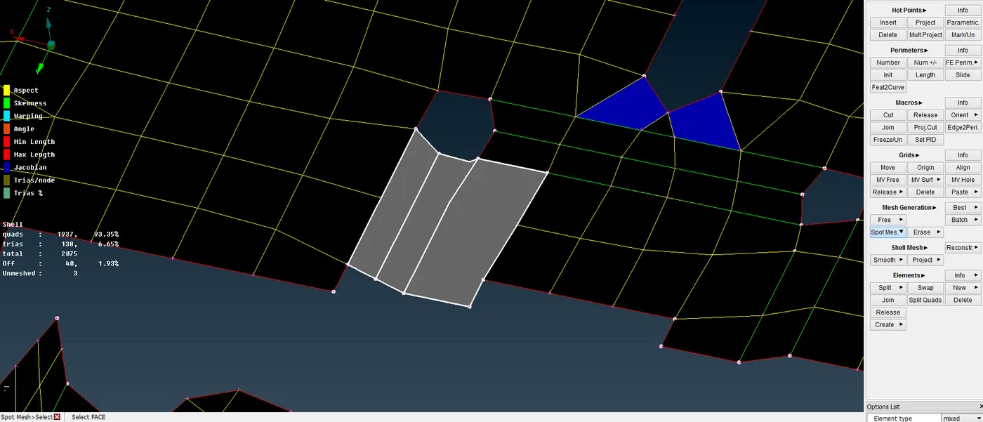
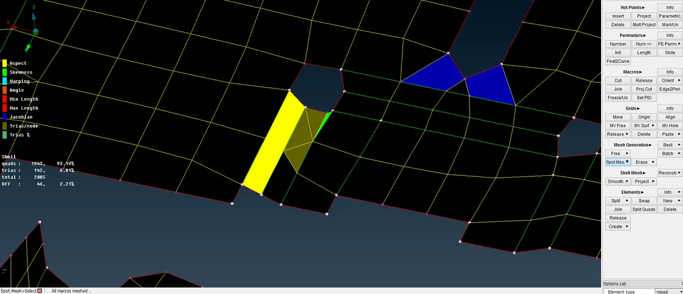
To obtain a better mesh flow, the mesh is re-constructed using the RECONSTRUCT command which is under the SHELL MESH module button in the MESH mode.
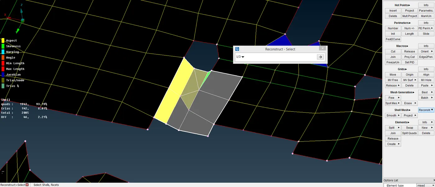
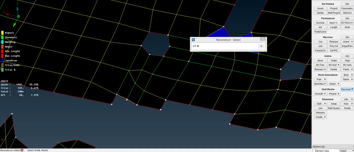
Here we can see two fillets with and without the construction line enabled. This is the difference created in the feature capturing with and without the fillet.
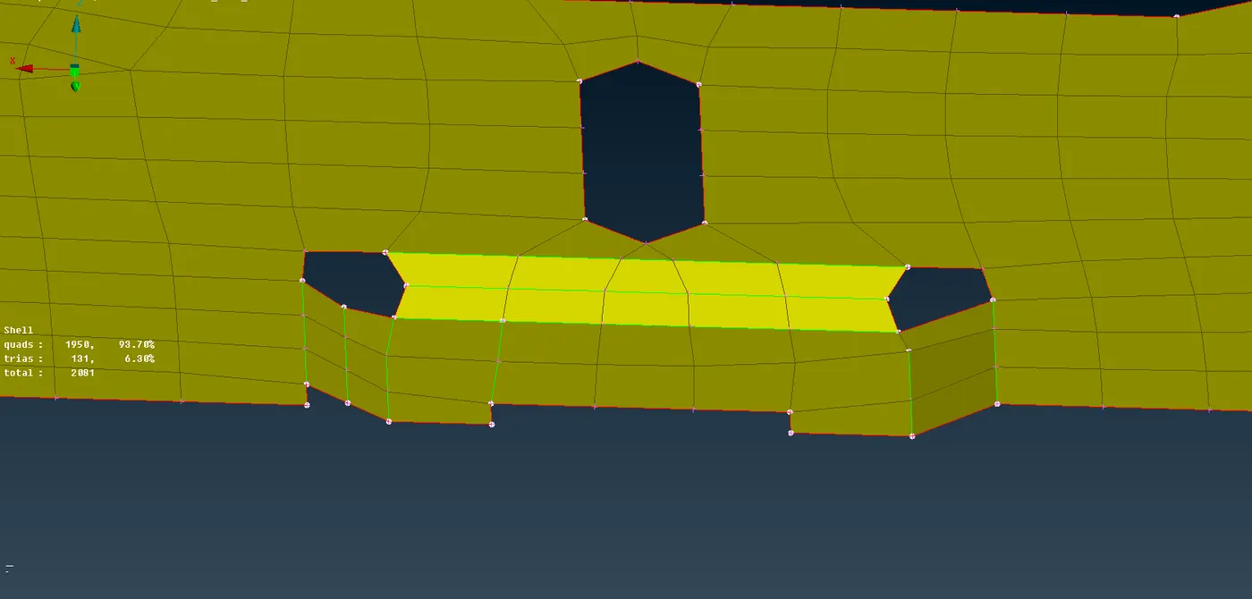
At another instance, we can see a construction line disabled. With the construction line enabled, the feature capturing for the fillet would be better.
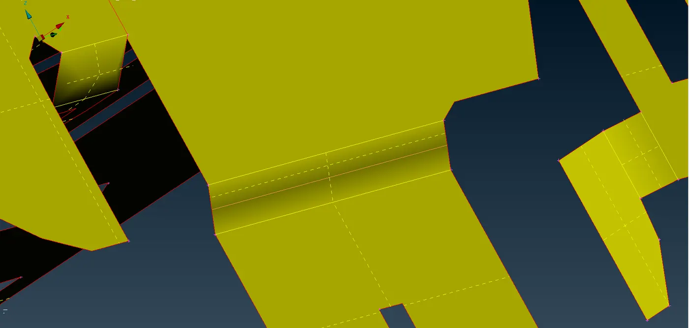
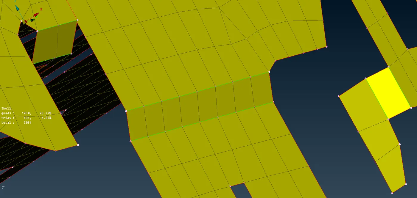
But there is a difference between the previous instance and the current one. In the previous instance, the construction line was not enclosed within a small macro area. So we had to create as small macro area around the construction line. But in this instance the construction line is already enclosed within a small macro area.
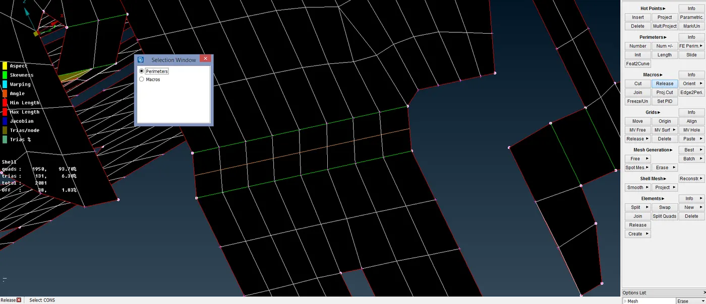
So the EDGE2PERIMETER command need not be used now. The construction line can be enabled using the MACROS -> RELEASE command and the macro area can be re-meshed.
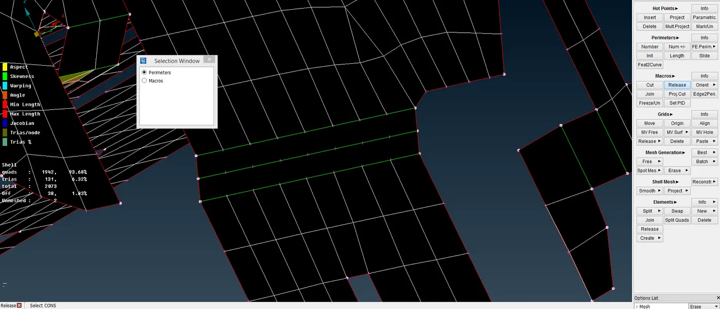
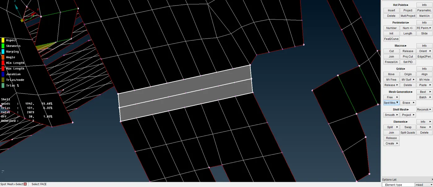
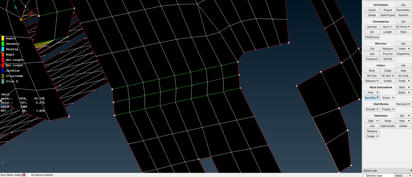
This way, the missed feature capturing is identified and is corrected manually.
CASTING:
Casting is a method which extracts the mid-surface from the CAD geometry, meshes the mid-surface and releases the FE elements from the CAD geometry. This way it creates an FE which is independent of the CAD geometry. This method is used mainly for components with varying thickness.
The CASTING command is under the FACES -> MID. SURFACE module button in the MESH mode.
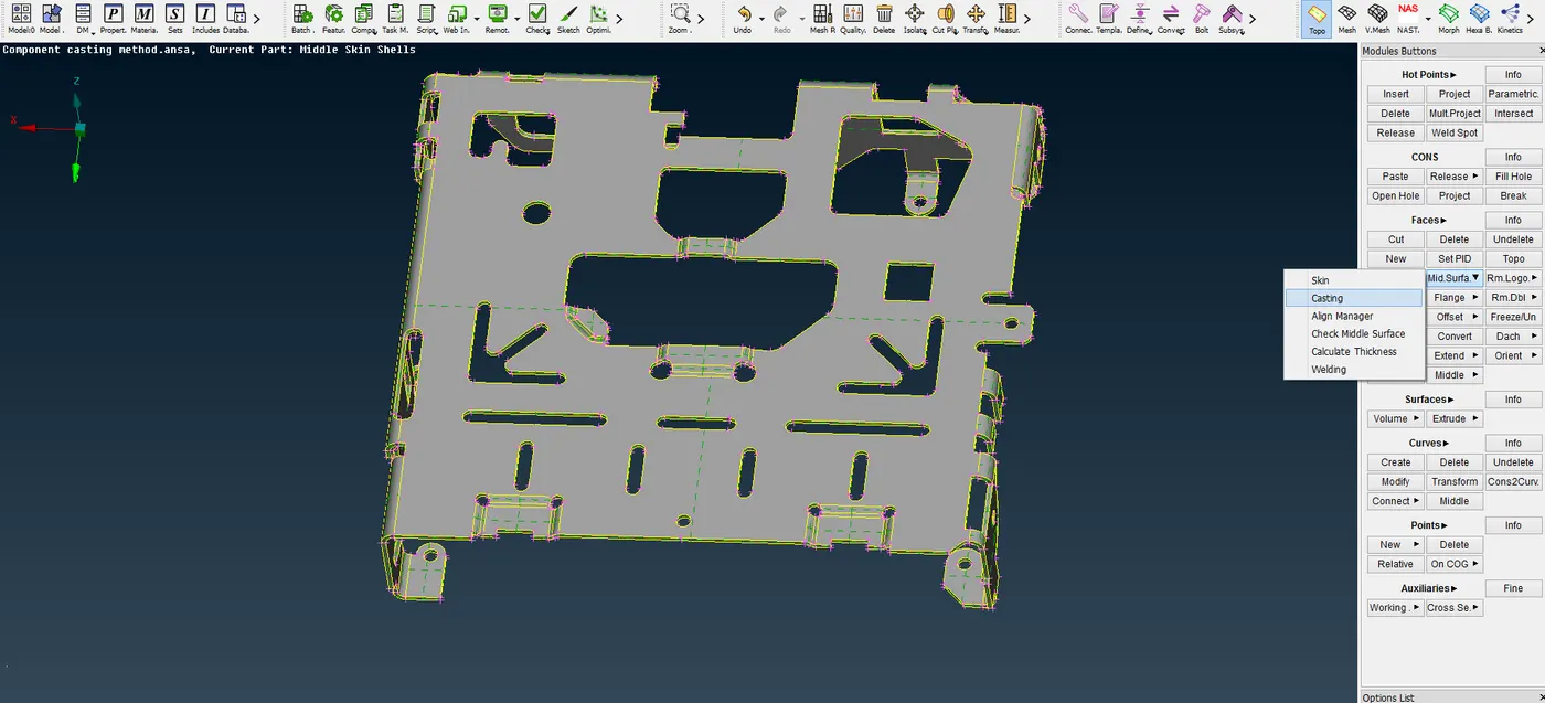
In the “AUTOMATIC MIDDLE-SURFACE MESH GENERATOR” dialog box, the minimum thickness of the CAD model is given. This is used for treating fillets as features. Then the Target element length is given.
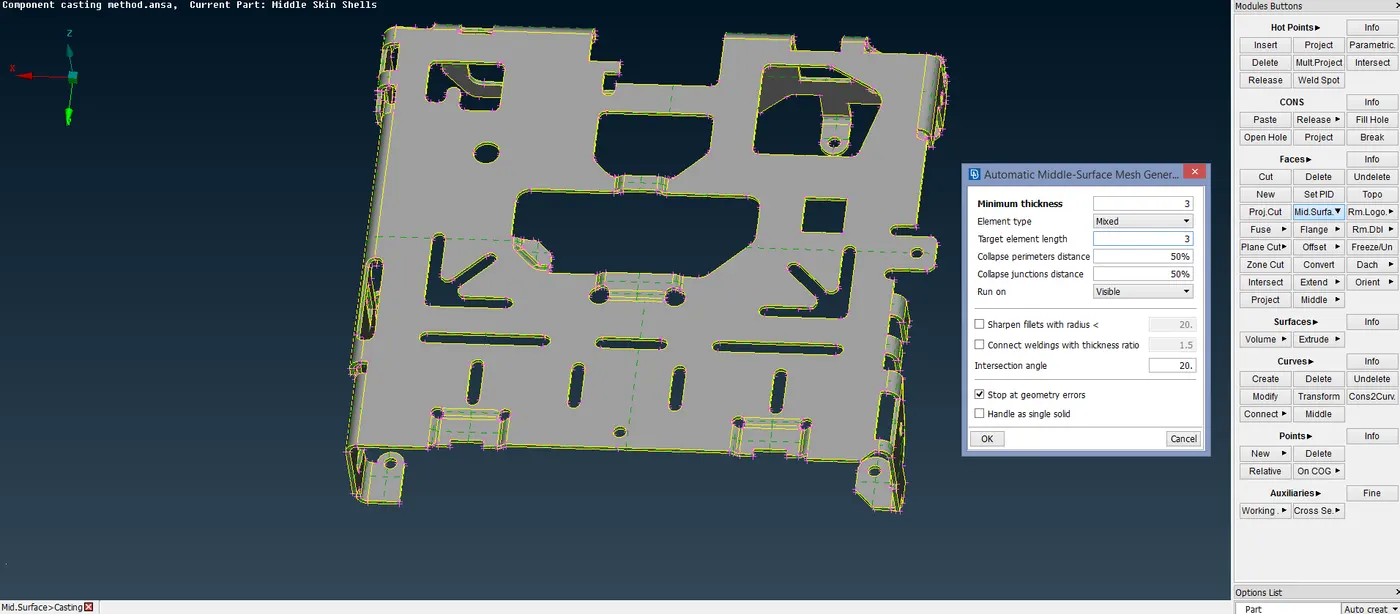
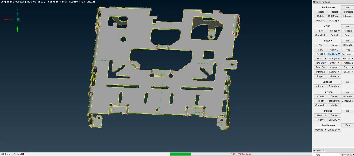
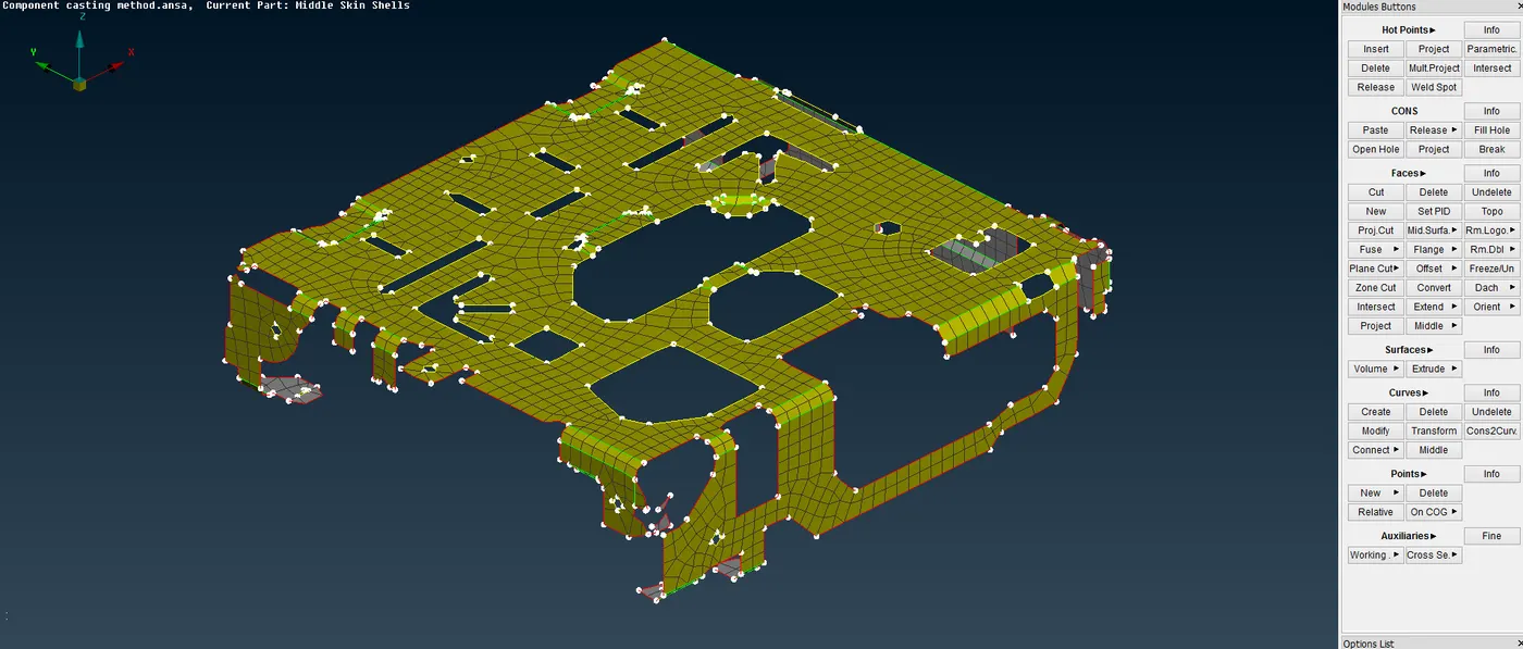
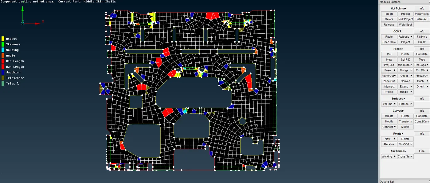
Upon executing, the mid-surface is generated & meshed and the mesh elements (FE) are released from the CAD model.
RESOLVING QUALITY ISSUES:
After the meshing, we will have FE elements failing for the set quality criteria. They need to be rectified and the errors need to be solved.
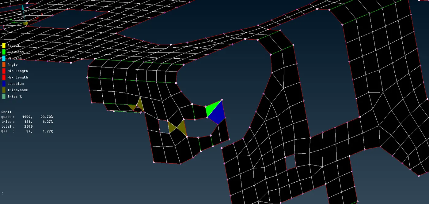
Here we can see that two elements are failing. One of them is failing for Skewness and the other for Jacobian. This can be solved using the SPLIT command which is under the ELEMENTS module button in the MESH mode. After enabling the command, the edge of the FE element is selected and accepted.
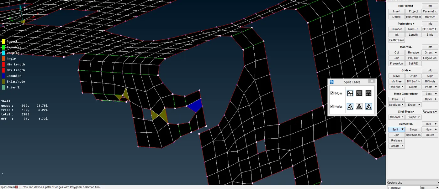
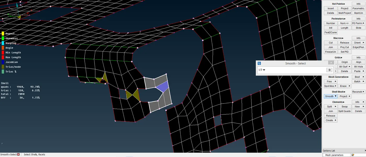
Then by doing a SMOOTH the mesh is smoothened and the quality issue is solved.
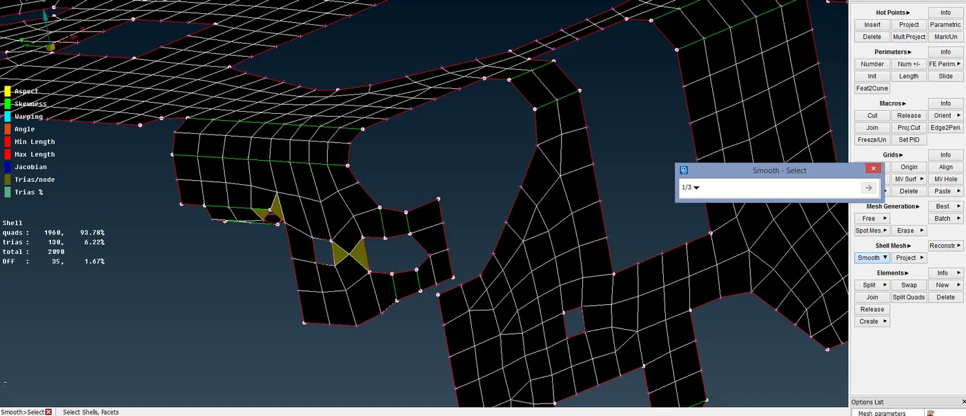
At another place we have a Maximum element length issue.
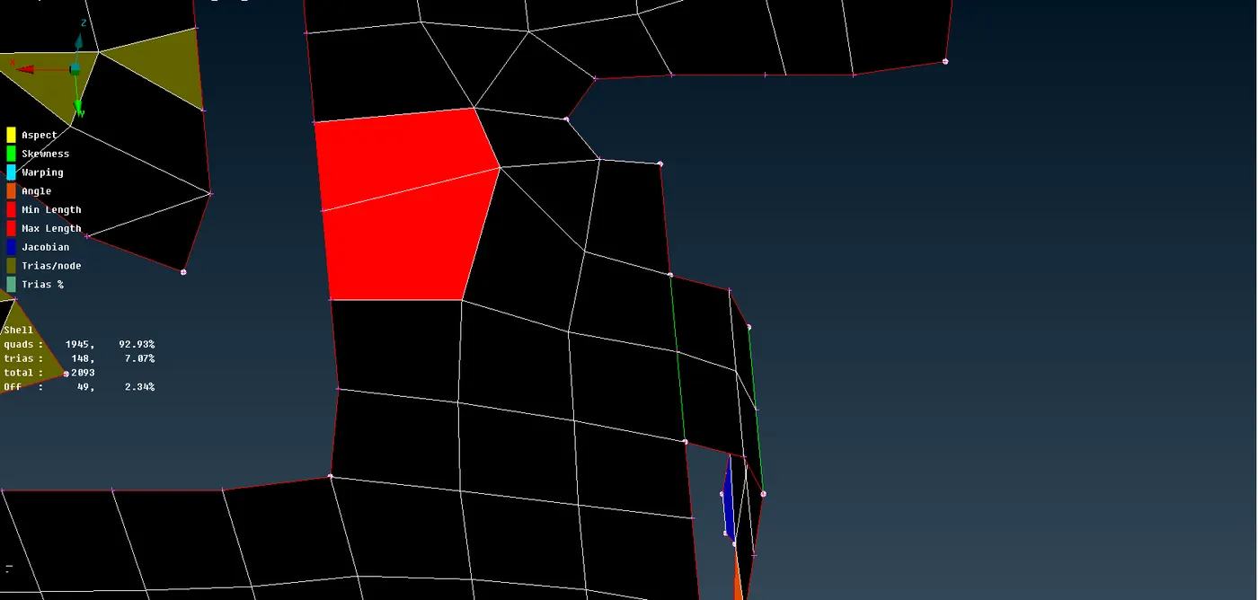
Similarly, nearby there is a tria element. The maximum element issue can be solved by using the SPLIT command.
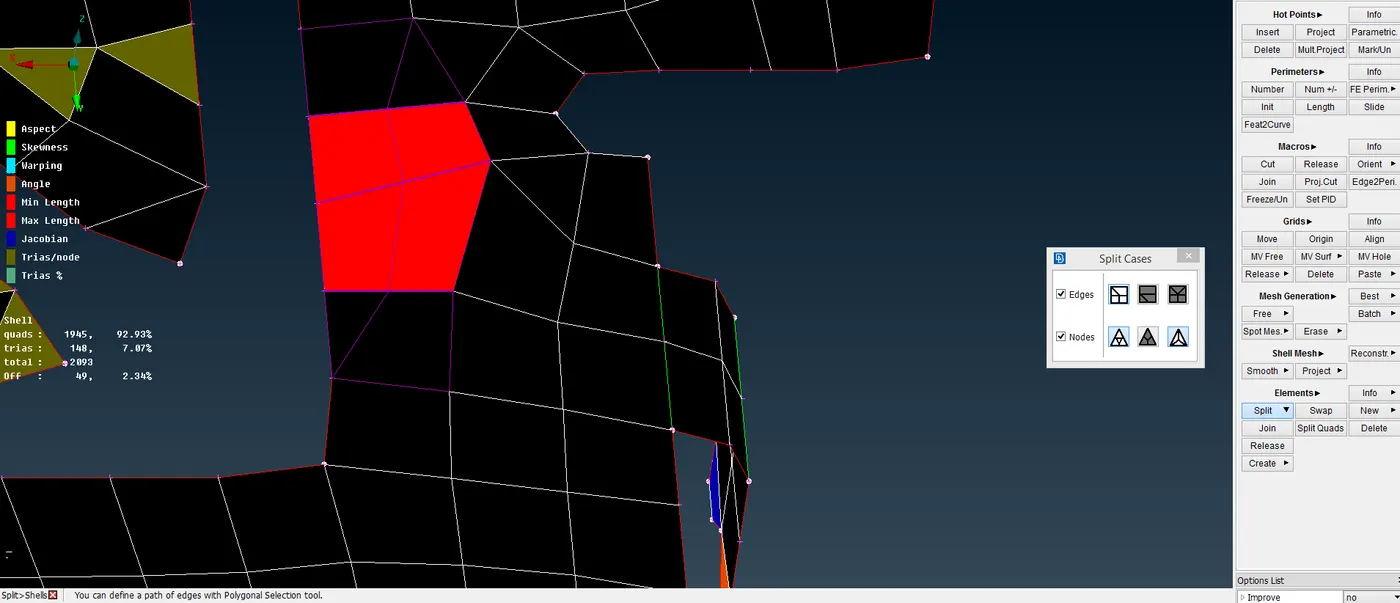
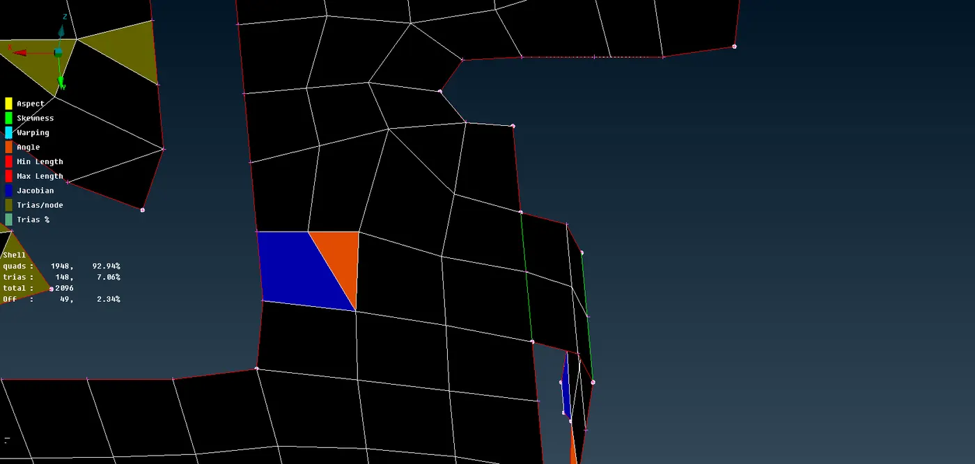
Then by doing a SMOOTH the mesh is smoothened and the quality issue is solved.
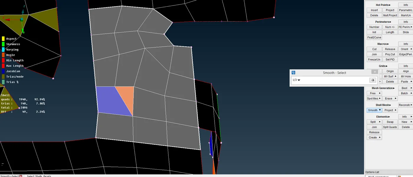
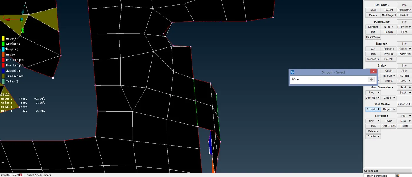
Here, we can find that there are two tria elements sharing a node with each other. Two tria elements should not share a common node/edge with each other.
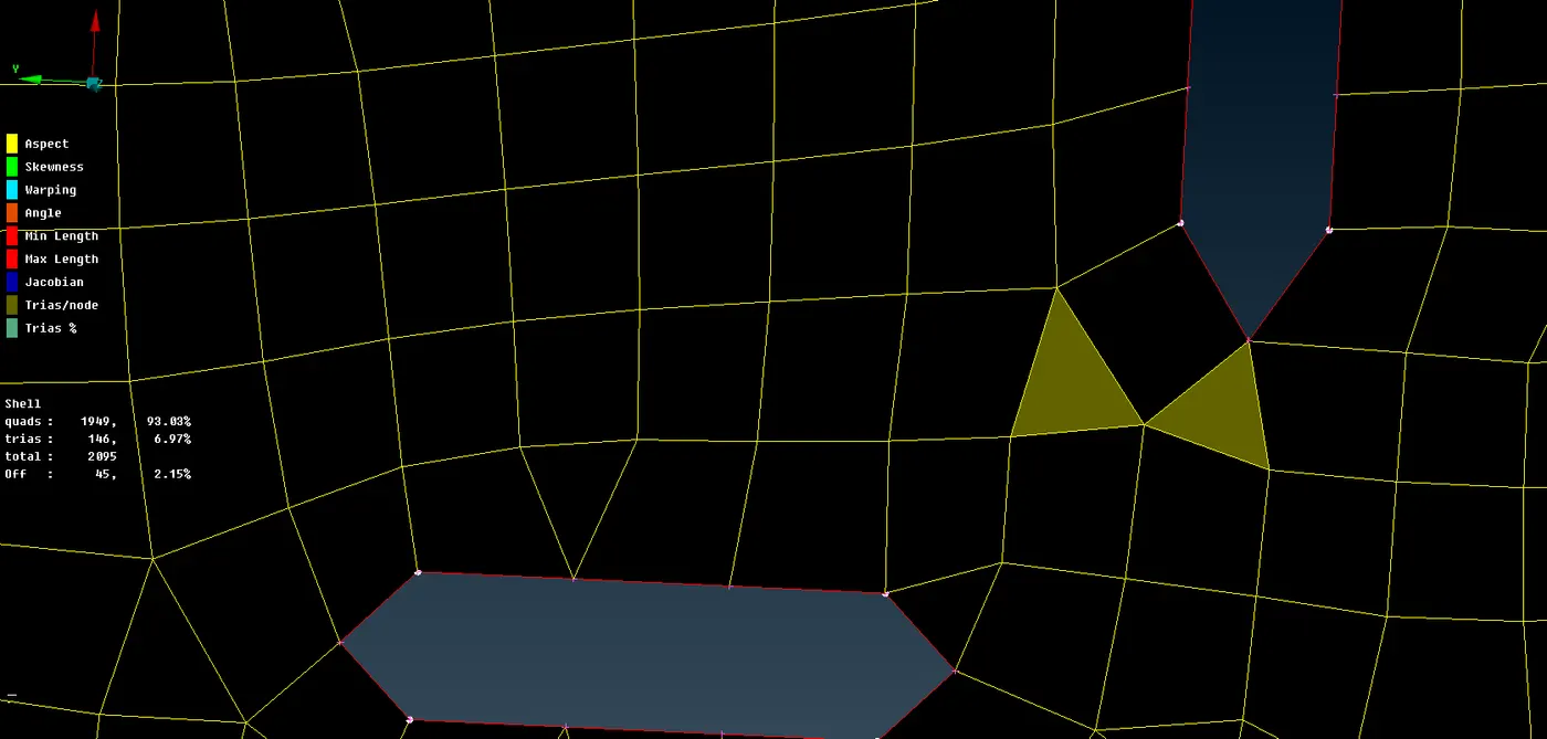
Similarly, we use the SPLIT command and solve the quality issue by doing a SMOOTH on the mesh.
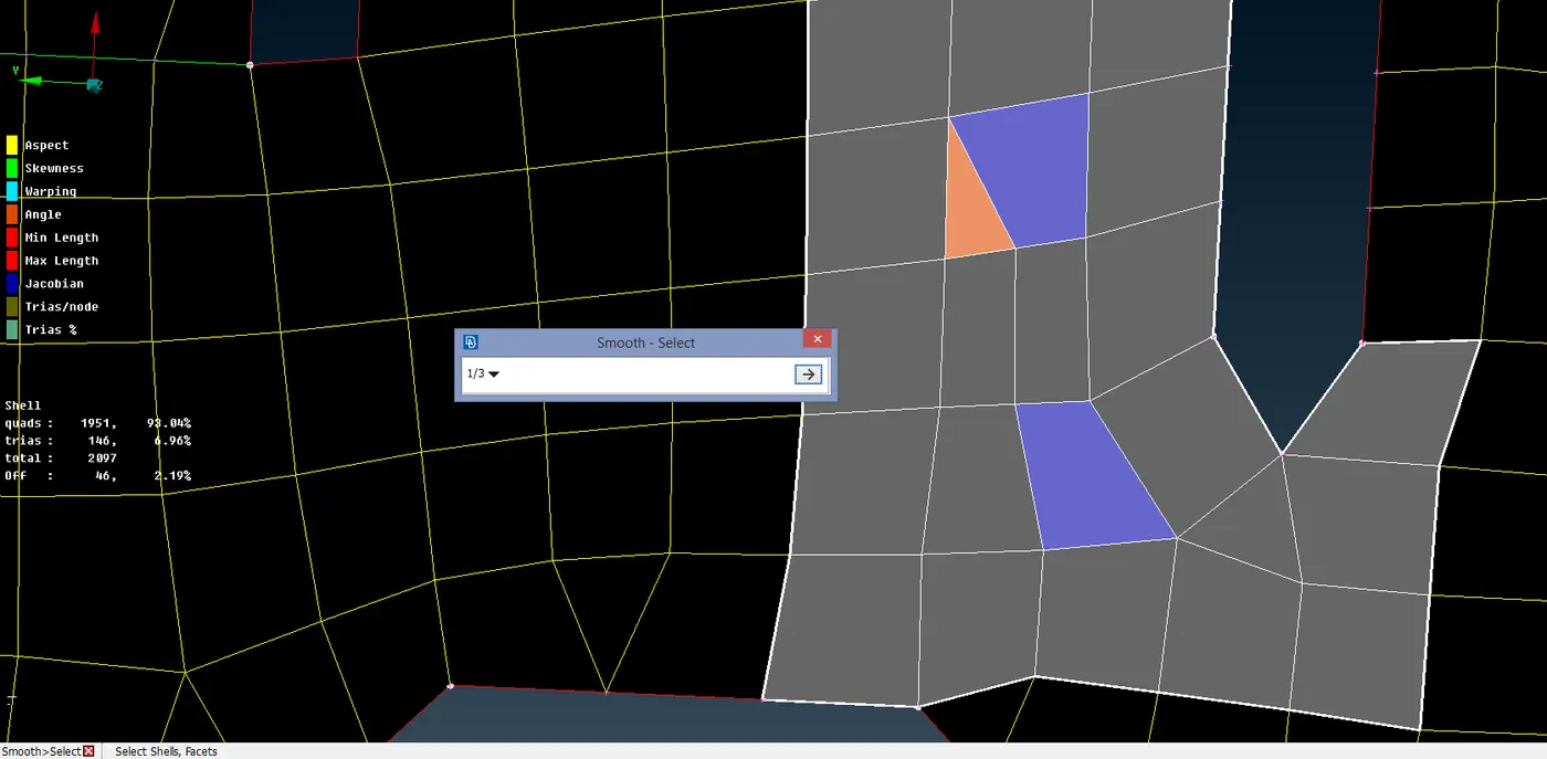
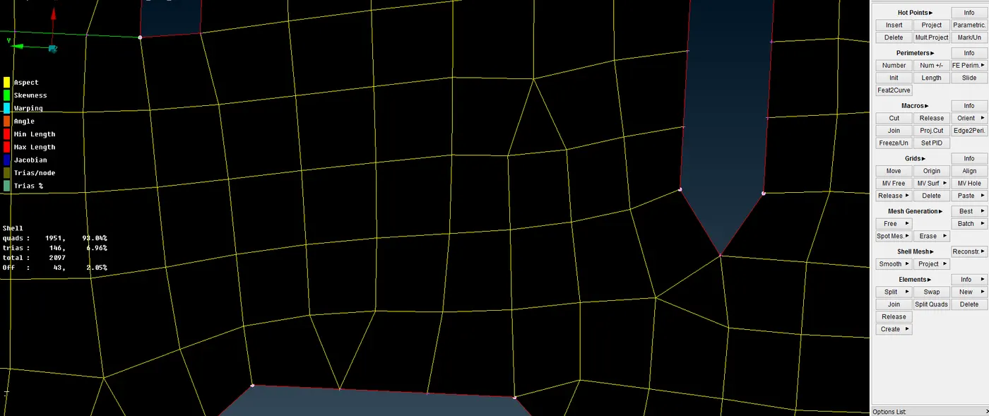
At another instance, we find another pair of trias sharing a node with each other.
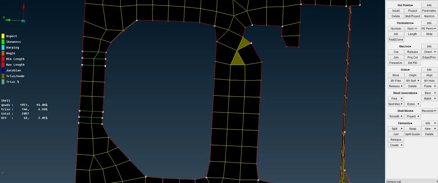
This can be solved by using the PASTE command which is under the GRIDS command button. By selecting the nodes of one tria and pasting them, the tria moves towards the downward direction.
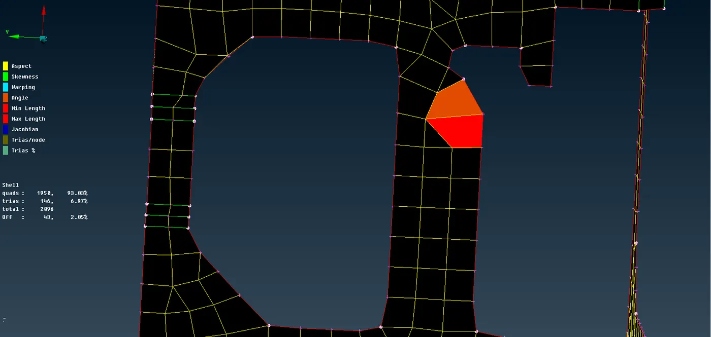
Now we can see two trias facing opposite to each other. This is called as OPPOSITE TRIAS. This is solved using the SPLIT command is used and the opposite trias are combined into a quad element.
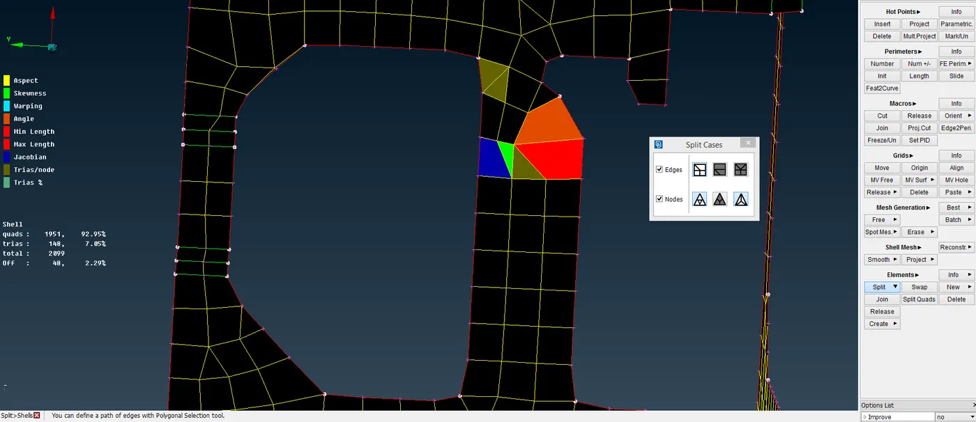
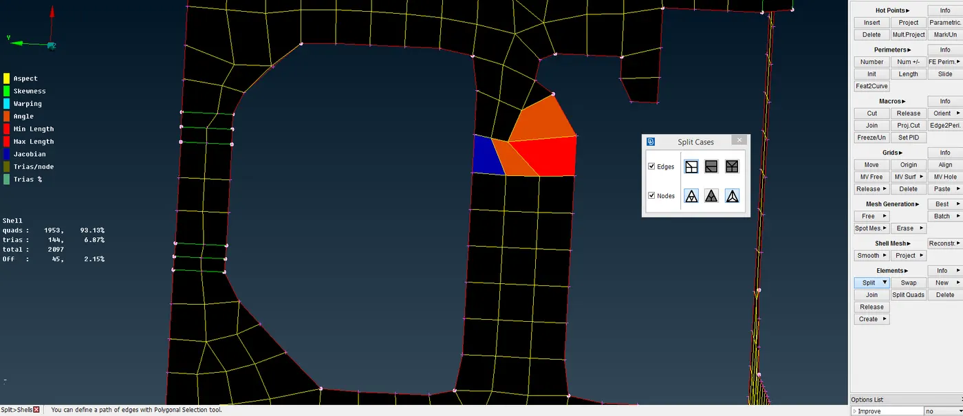
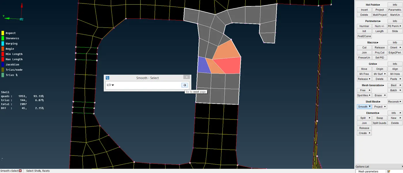
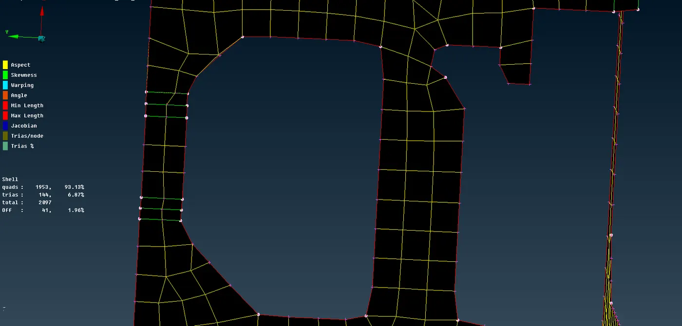
Then the SMOOTH command is used and the mesh is smoothened.
LEARNING OUTCOME:
- Manual mid-surfacing and manual meshing is the accurate method of mid-surfacing & meshing but is time-consuming.
- Skin option for mid-surfacing is ideal for components of uniform thickness and is less time-consuming.
- Batch meshing has de-featuring criteria which varies model to model.
- Construction lines which are required for feature capturing may be disabled during meshing and need to be checked in Batch meshing.
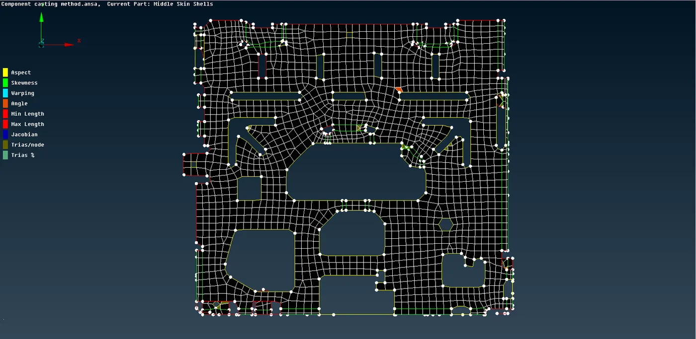
- Casting method contains lots of de-featuring and the mesh flow is not good. There are more quality issues in the mesh.
- Feature capturing is very less in the casting method compared to other methods and needs to be corrected manually.
Tria %:
- Casting - 3.89%
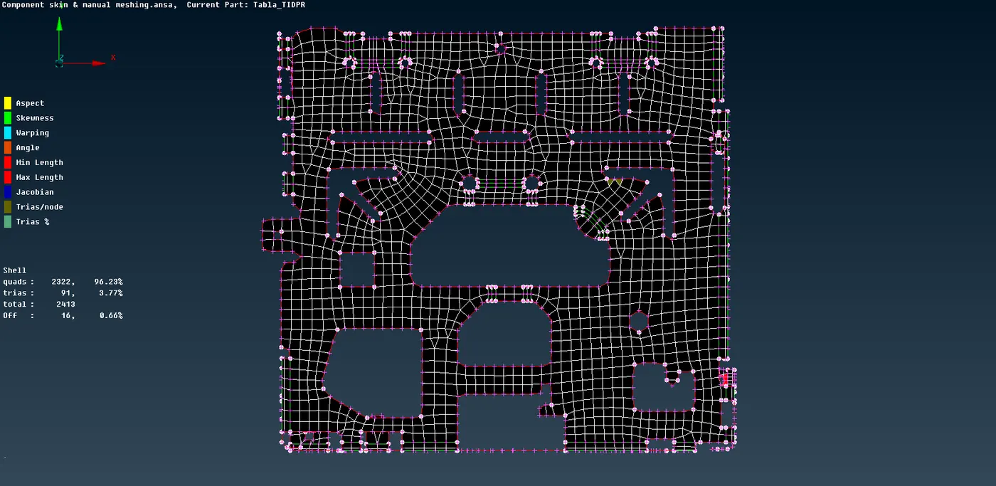
- Skin option & manual meshing 3.77%
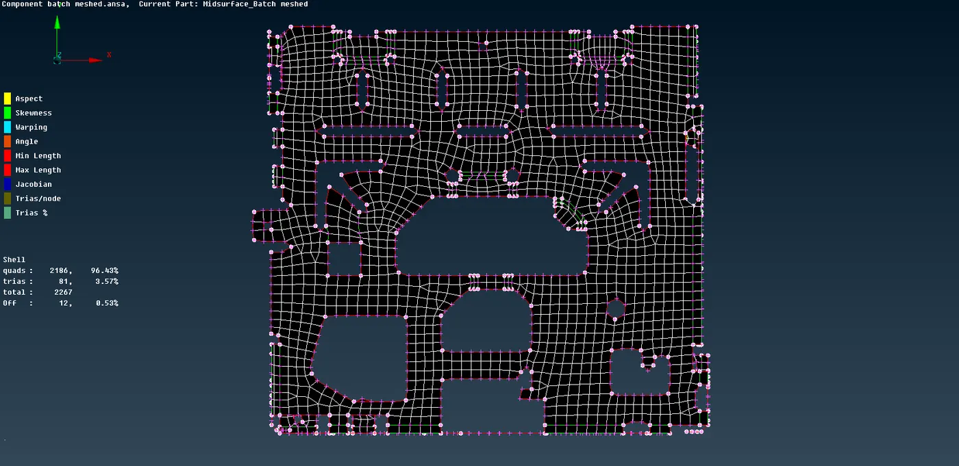
- Manual mid-surfacing & Batch meshing - 3.57%
CONCLUSION:
If there is no much complication in the CAD model and if the feature capturing can be rectified after meshing, Batch meshing is the Best method for meshing.
In case of a component of uniform thickness, Skin option is very useful to extract the mid-surface with less amount of time being consumed.