Shell Meshing of Hood using HyperMesh
AIM:
To extract mid-surface of the CAD model & mesh with the given quality criteria.
OBJECTIVE:
The objective of the project is to learn to extract mid-surface and mesh the mid-surface with given quality criteria with least failing elements.
PROCESS:
1. Perform geometry cleanup.
2. Mid-surface extraction.
3. Defeaturing.
4. Meshing.
5. Clearing quality issues.
PROCEDURE:
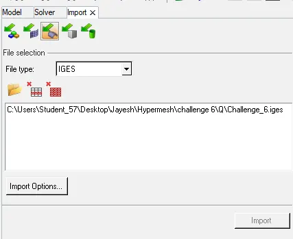
First the CAD model is imported using the import geometry option.
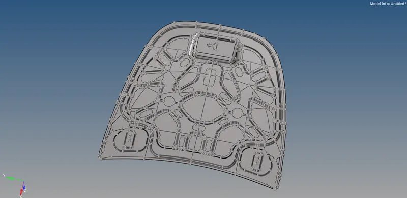
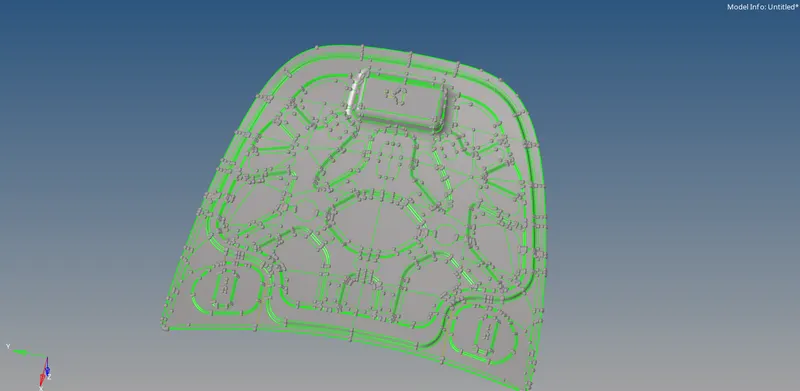
- Then the visualisation mode is changed to Topo so that the various types of curves can be seen.
- Then the thickness of the CAD model is measured using the distance command in the geometry panel. The two points option is selected and the distance between two points are measured in various places.


- Once the thickness of the model is known, the mid-surface is extracted using the midsurface command in the geometry panel.

- The offset option is used in the extraction options.

- Once the mid-surface is extracted, the washers are created around holes using the washer split command. The width of the washer is kept as the target element length.

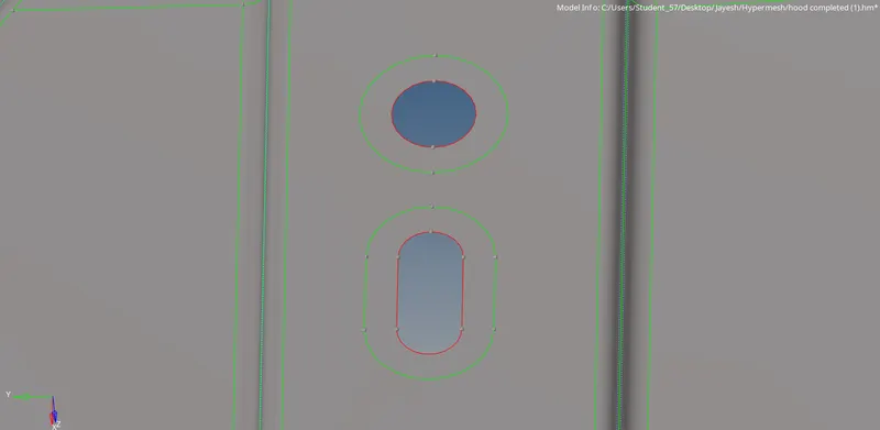
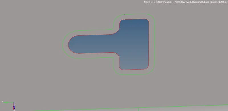
- The construction lines or feature lines are re-arranged so that they capture the features such as fillets, curves, etc. properly and also the best possible mesh flow is achievable.
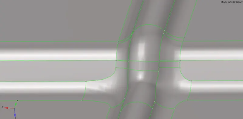
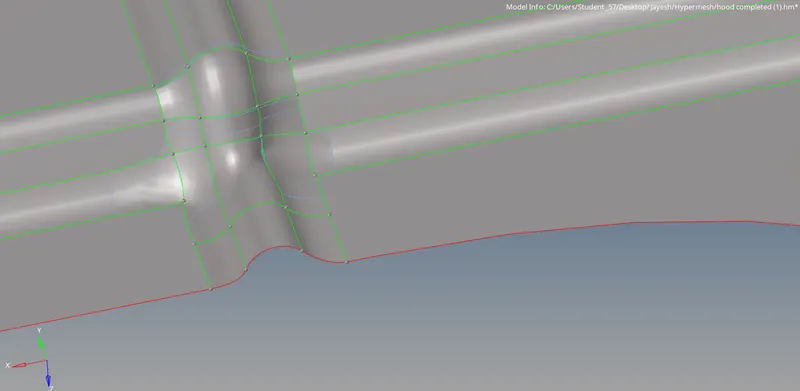
- In places where the construction lines are very close causing minimum element length failure, they are re-arranged by toggling some lines and having as minimum lines as possible.

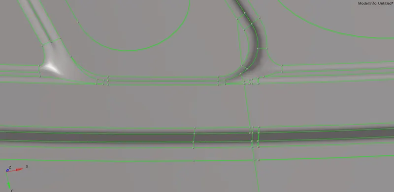
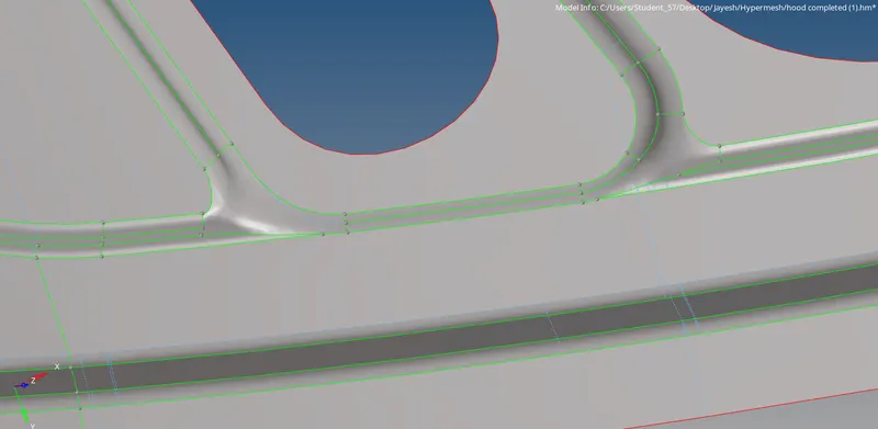
- In large flat surfaces, the lines can be arranged in box-fashion to achieve good mesh flow.
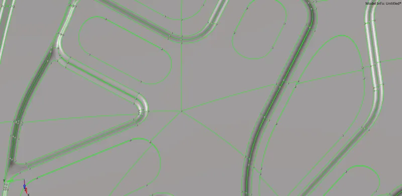
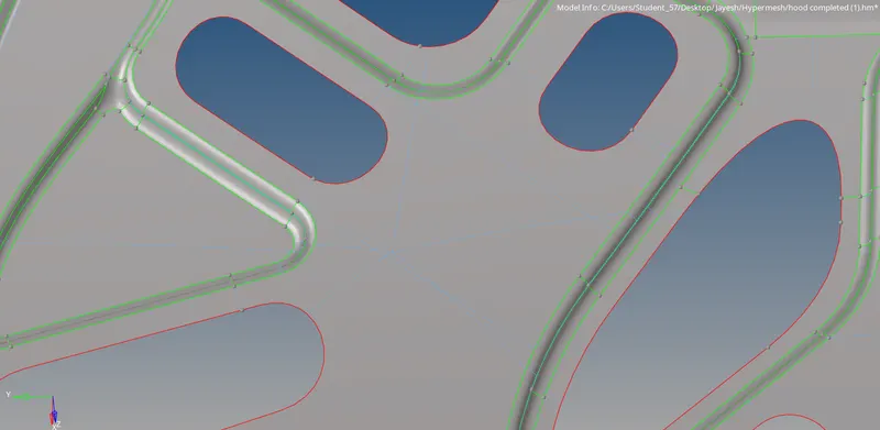
- Once the construction lines are re-arranged, the quality criteria is set and then the meshing is done using the automesh command.
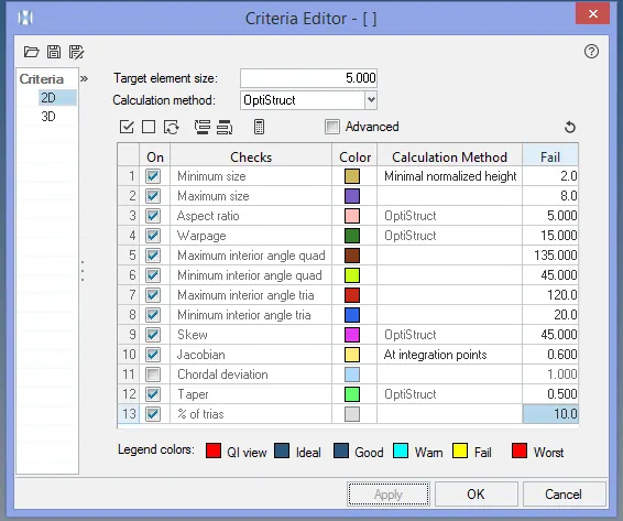

- The meshing is done on one half of the surfaces as the CAD model is symmetrical. Once the meshing and refining of the mesh is completed, the mesh is reflected using the reflect command.

- After reflecting the mesh, the mandatory checks are done. First check is for edges. It is done using the edges command button in the tool panel. The component is selected and free edges in the FE is found. The free edges, if any, are suppressed (equivalence). Using the tolerance, the value is increased to find free edges further.



- The next check is for normals. It is done to check the direction of the force acting when it is applied on the FE. It can be checked using the color display (Red & blue) or using the vectors depicting the directions.

- The next check is for penetration. It is done by selecting the whole FE, After the check is completed, the results are displayed in the area on the left.

RESULTS:
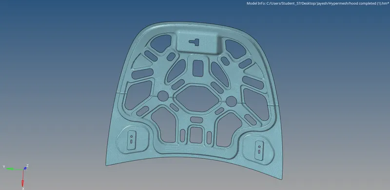
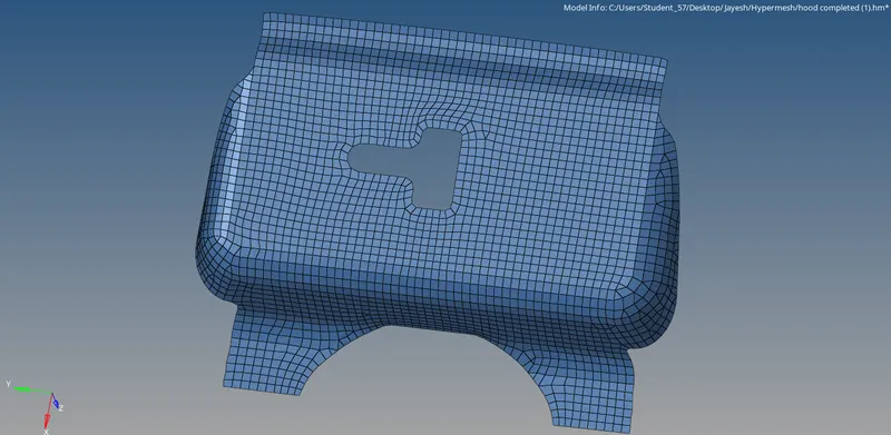
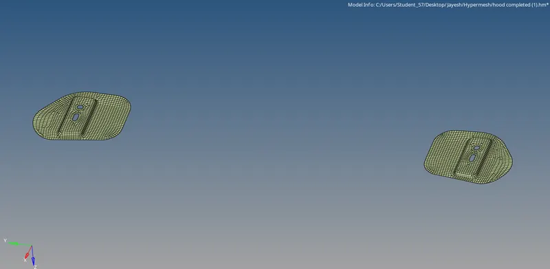
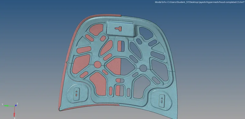
After meshing and reflecting the FE, we obtain the complete meshed model.
Inner hood
Outer hood
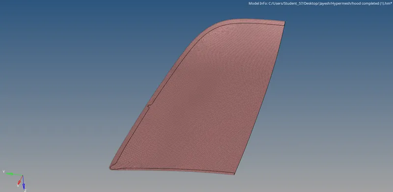
NOTE: The outer hood FE could not be reflected as the no. of nodes exceeded the limit. All the other FE models are reflected and the necessary checks are completed.
Latch reinforcement
Component 3 & 4
Completed model
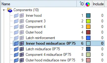
Component collectors
CONCLUSION:
Thus the mid-surface is extracted and meshed for the given CAD model with the given quality criteria.
NOTE: The outer hood FE could not be reflected as the no. of nodes exceeded the limit. All the other FE models are reflected and the necessary checks are completed.