Week 8 - Simulating Cyclone separator with Discrete Phase Modelling
Simulating Cyclone separator with Discrete Phase Modelling
Objectives:
- To explore empirical models used to calculate the cyclone separator efficiency and to perform an analysis on a given cyclone separator model by varying the particle diameter from 1 μm to 5 μm at constant velocity of 3m/s and calculate the separation efficiency in each case.
- To perform an analysis on a given cyclone separator model by varying the particle velocity from 1 m/sec to 5 m/sec at particle diameter size of 5 μm and calculate the separation efficiency and pressure drop in each case.
Cyclone Separators:
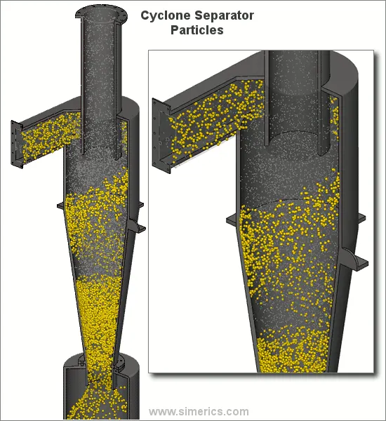
- Cyclone separators provide a method of removing particulate matter from air or other gas streams at low cost and low maintenance.
- Cyclones are basically centrifugal separators, consisting of an upper cylindrical part referred to as the barrel and a lower conical part referred to as the cone.
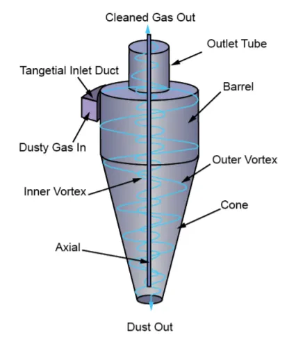
- They simply transform the inertia force of gas-particle flows to a centrifugal force by means of a vortex generated in the cyclone body.
- The particle-laden air stream enters tangentially at the top of the barrel and travels downward into the cone, forming an outer vortex. The increasing air velocity in the outer vortex results in a centrifugal force on the particles, separating them from the air stream. When the air reaches the bottom of the cone, it begins to flow radially inwards and out the top as clean air/gas while the particulates fall into the dust collection chamber attached to the bottom of the cyclone.
Types:
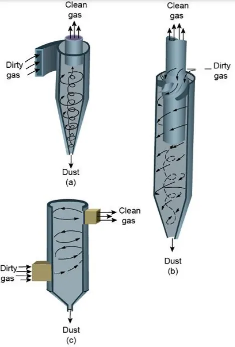
- (a)cyclone with a tangential entry. These types of cyclones have a distinctive and easily recognized form and are widely used in power and cement plants, feed mills, and many other process industries.
- (b) shows the axial entry cyclones, the gas enter parallel to the axis of the cyclone body. In this case, the dust-laden gases enter from the top and are directed into a vortex pattern by the vanes attached to the central tube. Axial entry units are commonly
used in the multi-cyclone configuration, as these units provide higher efficiencies. - (c) is often used after wet scrubbers to trap particulate matter entrained in water droplets. In this type, the air enters tangentially at the bottom, forming a vertex. Large water droplets are forced against the walls and are removed from the air stream.
Efficiency:
- Cyclone collectors can be designed for many applications, and they are typically categorized as high efficiency, conventional (medium efficiency), or high throughput (low efficiency). High-efficiency cyclones are likely to have the highest-pressure drops of the three cyclone types, while high-throughput cyclones are designed to treat large volumes of gas with a low-pressure drop. Each of these three cyclone types has the same basic design. Different levels of collection efficiency and operation are achieved by varying the standard cyclone dimensions.
- The collection efficiency of cyclones varies as a function of density, particle size and cyclone design. Cyclone efficiency will generally increase with increases in particle size and/or density; inlet duct velocity; cyclone body length; number of gas revolutions in the cyclone; ratio of cyclone body diameter to gas exit diameter; inlet dust loading; smoothness of the cyclone inner wall.
- Cyclone efficiency will decrease with increases in the parameters such as gas viscosity; cyclone body diameter; gas exit diameter; gas inlet duct area; gas density; leakage of air into the dust outlet.
(i) Cyclone Performance-Centrifugal Force
Cyclones are basically centrifugal separators. They simply transform the inertia force of gas particles to a centrifugal force by means of a vortex generated in the cyclone body. The particle-laden gas enters tangentially at the upper part and passes through the body, describing the vortex. Particles are driven to the walls by centrifugal forces, losing their momentum and falling down to the cyclone leg. In the lower section, the gas begins to flow radially inwards to the axis and spins upwards to the gas outlet duct. Particles are driven to the walls by centrifugal forces given by the expression,
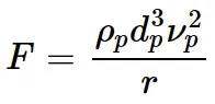
Where,
 = particle density in kg/m3
 = particle diameter in μm
 = particle tangential velocity in m/s
r = radius of the circular path in m
The main variables describing the cyclone performance are pressure drop, efficiency, and cut diameter.
1) Cut Diameter
The cut diameter of the cyclone is defined as the size of the particles collected with 50% collection efficiency. It is an indicator of the size range of particles that can be collected. It is a convenient way of defining as it provides information on the effectiveness for a particle size range. A frequently used expression for cut-off diameter is
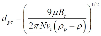
where,
μ=viscosity in Pa.s
Bc=inlet width in m
N= effective number of turns, Given the volumetric flow rate, inlet velocity, and dimension of the cyclone, N can be easily calculated. Values of N can vary from 1 to 10, with typical values in the 4-5 range.
 = inlet gas velocity in m/s
 = particle density in (kg)/m^3
 = gas density in (kg)/m^3
2) Collection Efficiency
The collection or separation efficiency is most properly defined for a given particle size. Experience shows that the collection efficiency of cyclone separator increases with increasing particle mean diameter and density; increasing gas tangential velocity; decreasing cyclone diameter; increasing cyclone length; extraction of gas along with solids through the cyclone legs.
Iozia and Leith Model:
It is developed based on force balance on which Barth Model. The model assumes that a particle carried by the vortex endures the influence of two forces: centrifugal force, and flow resistance.
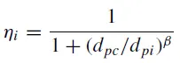
Beta is an expression for slope parameter derived based on the statistical analysis of experimental data of a cyclone with D = 0.25 m given as

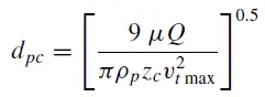
where dpc is the 50% cut size given by Barth
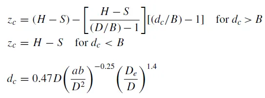
Here, zc is the core length and the dc is the core diameter.
Li and Wang Model: (Ref [1])
The Li and Wang model includes particle bounce or re-entrainment and turbulent diffusion at the cyclone wall. A two-dimensional analytical expression of particle distribution in the cyclone is obtained. Li and Wang model was developed based on the following assumptions:
• The radial particle velocity and the radial concentration profile are not constant for uncollected particles within the cyclone.
• Boundary conditions with the consideration of turbulent diffusion coefficient and particle bounce re-entrainment on the cyclone
Koch and Licht Model: (Ref [1])
This model recognized the inherently turbulent nature of cyclones and the distribution of gas residence times within the cyclone. Koch and Licht described particle motion in the entry and collection regions with the following additional assumptions:
• The tangential velocity of a particle is equal to the tangential velocity of the gas flow, i.e., there is no slip in the tangential direction between the particle and the gas.
• The tangential velocity is related to the radius of the cyclone by: uR^n = constant.
Lapple Model: (Ref [1])
It is developed based on force balance without considering the flow resistance. Lapple assumed that a particle entering the cyclone is evenly distributed across the inlet opening. The particle that travels from the inlet half-width to the wall in the cyclone is collected with 50% efficiency.
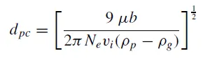
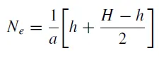
where Ne is the number of revolutions, a cyclone inlet height (m), H cyclone height (m), h cyclone cylinder height (m)
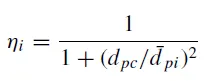
The efficiency of collection of any size of the particle is given by
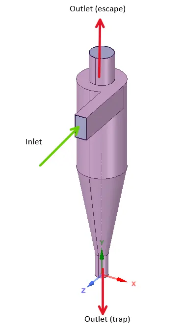
Geometry:
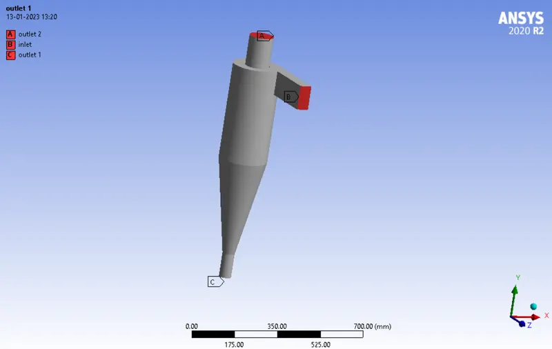
The given geometry consists of 1 inlet and two outlets, of which one is a trap to segregate particles and the other at the top is to eliminate the gases.
Meshing:
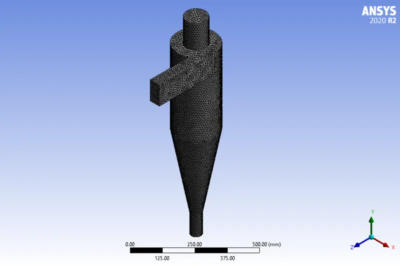
A default mesh with an element size of 10mm is created, leading to 111632 elements with 22771 nodes.
The regions are named as shown below. Outlet 1 acts as a trap to remove dust particles and Outlet 2 is for clean fluid.
Simulation Setup:
Solver: Steady State, Pressure based
Gravity: ON along Negative Y direction (-9.81 m/s2)
Viscous Model: RNG k-epsilon - it enhances swirling flows
Discrete Phase: ON
- Coupled Flow (Discrete phase with interact with Continous phase)
- Update DPM Sources every flow iteration
- DPM iteration interval: 10 - particles are tracked based on this value. A higher value would reduce computational efforts.
- Tracking parameters: Max number of steps: 50000, Solver stops tracking a particle if the max number of steps is reached.
- Step length Factor: 5 (Controls the time step, if length scale is turned ON, times step is calculated by dividing the length scale by the velocity of the discrete particle and the velocity of the continuous phase. Small value leads to higher time step and vice versa)
Injection:
Particle type: Inert
Material: Anthracite
Injection type: Surface
Diameter: uniform
Velocity : 3m/s along X
Diameter: 5e-06m
Total flow rate: 1e-20 kg/s
Boundary Conditions:
Inlet: velocity 3m/s, DPM - reflect
Wall: Stationary, DPM-reflect
Outlet 2 Top: atm pressure, DPM - escape
Outlet 1 Bottom: atm pressure, DPM - escape
Solution Methods:
- SIMPLE
- Momentum, Turbulent Kinetic energy, Turbulent Dissipation Rate - Second Order
Solution Initialisation:
- Standard
- Compute from Inlet
- Iterations: 600
Results:
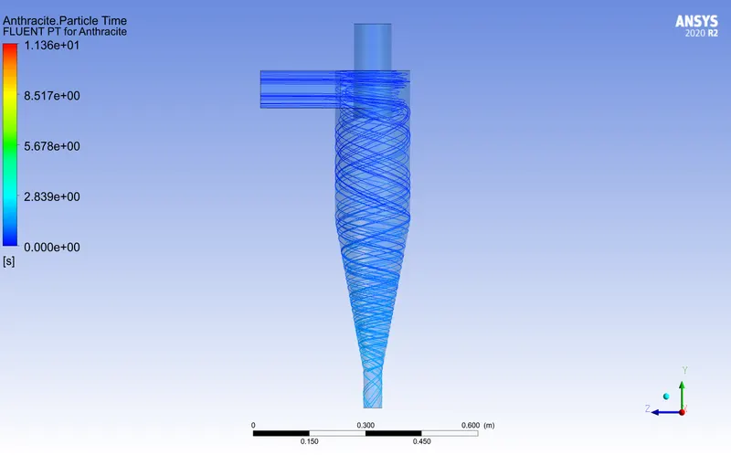
Particle size 5μm
Residence time:
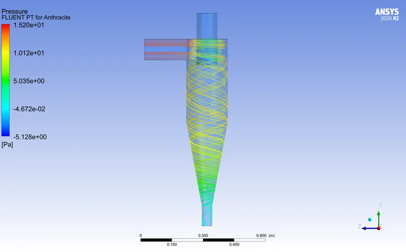
Pressure:
Velocity:
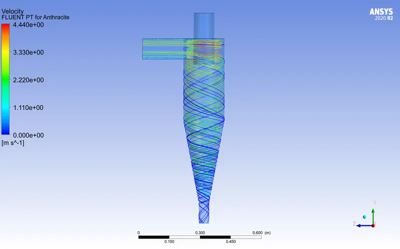
number tracked = 124, escaped = 5, trapped = 116, incomplete = 3
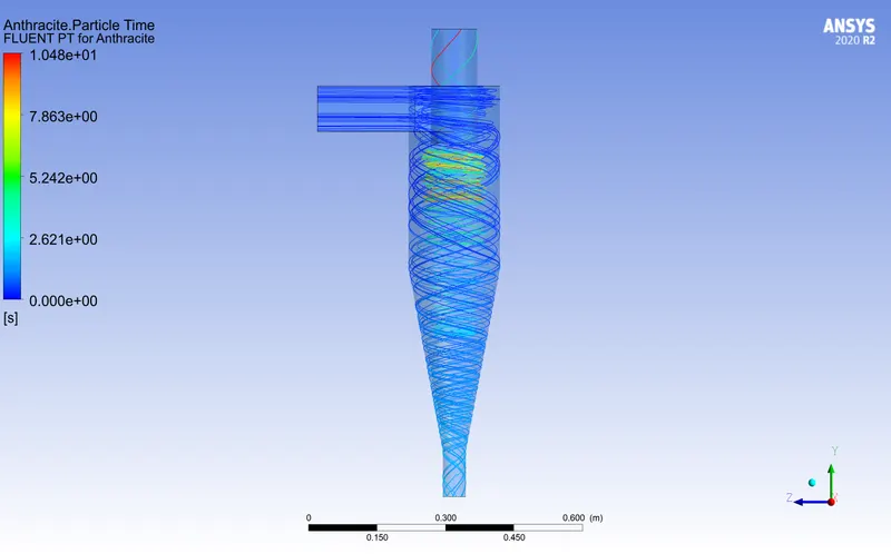
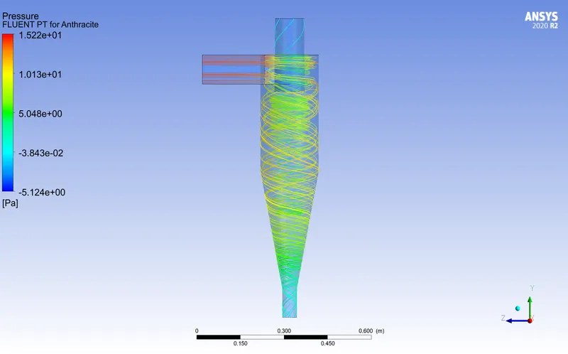
Particle size 4μm
Residence Time:
Pressure:
Velocity:
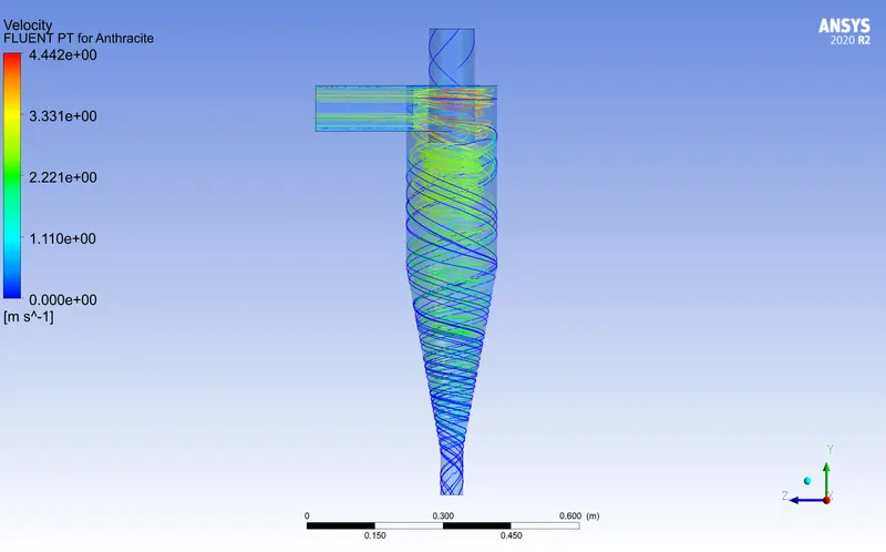
number tracked = 124, escaped = 8, trapped = 111, incomplete = 5
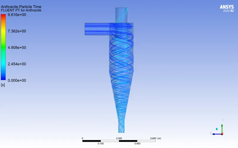
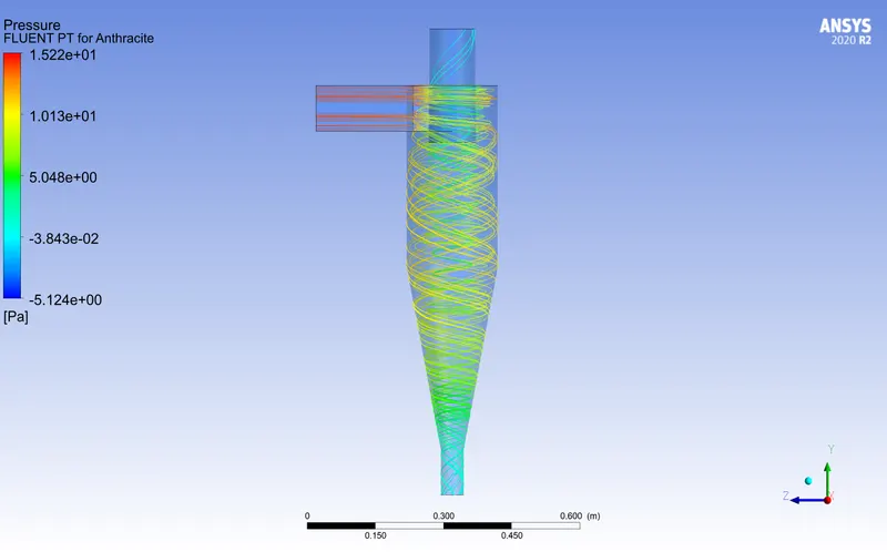
Particle size 3μm
Residence Time
Pressure:
Velocity:
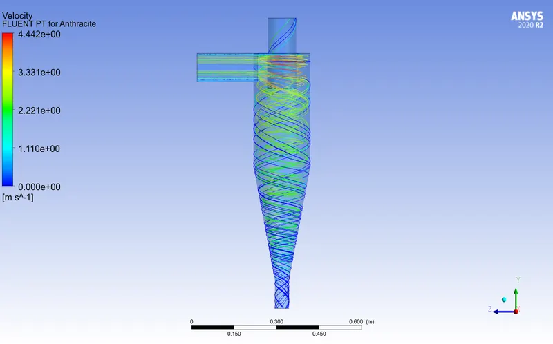
number tracked = 124, escaped = 21, trapped = 100, incomplete = 3
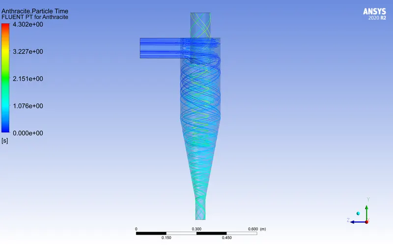
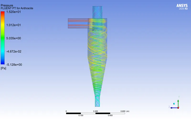
Particle size 2μm
Residence Time:
Pressure:
Velocity:
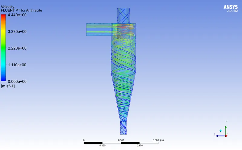
number tracked = 124, escaped = 33, trapped = 86, incomplete = 5
Particle size 1μm
Residence Time:
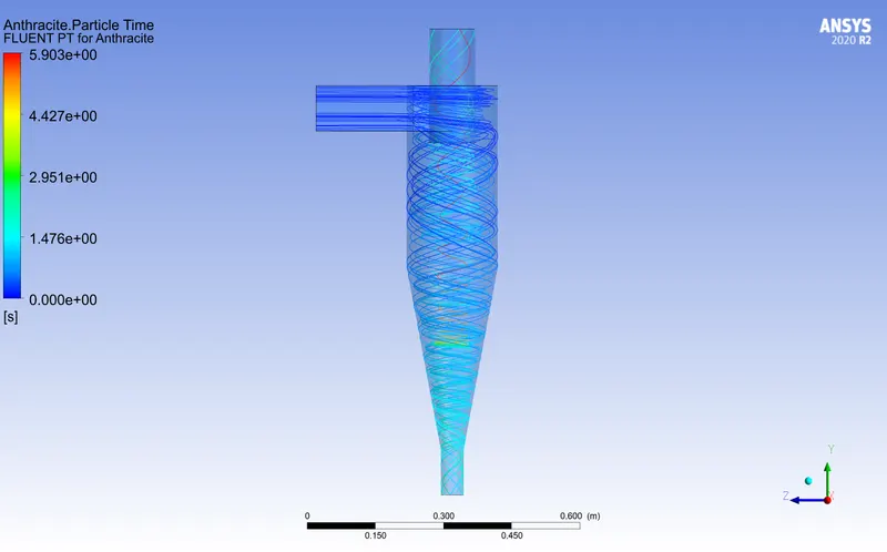
Pressure:
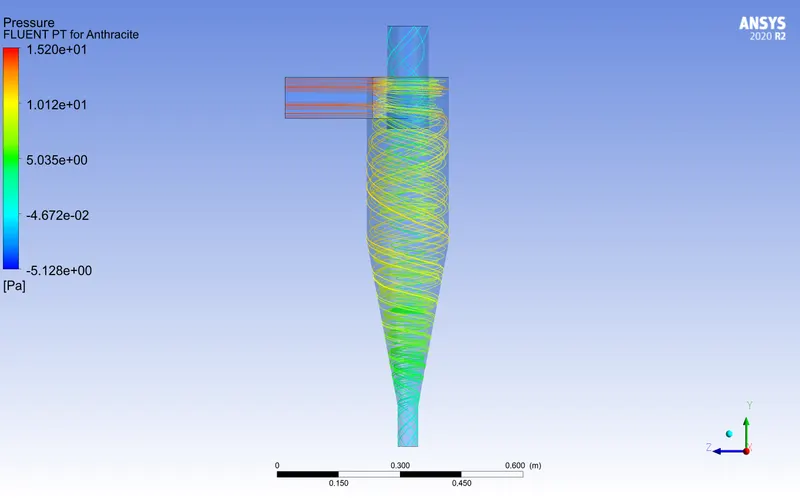
Velocity:
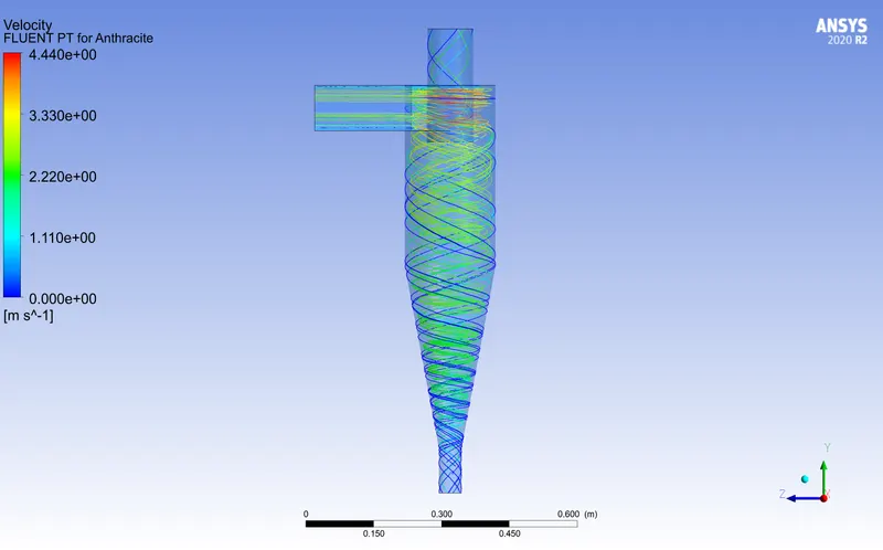
number tracked = 124, escaped = 33, trapped = 40, incomplete = 51
| Particle size | Tracked | Trapped | Efficiency % | Residence Time s | Velocity m/s | Pressure Difference Pa |
| 5μm | 124 | 116 | 93.5 | 11.36 | 4.44 | 20.32 |
| 4μm | 124 | 111 | 89.5 | 10.48 | 4.442 | 20.3 |
| 3μm | 124 | 100 | 80.6 | 9.81 | 4.442 | 20.3 |
| 2μm | 124 | 86 | 69.3 | 4.30 | 4.44 | 20.32 |
| 1μm | 124 | 40 | 32.2 | 5.90 | 4.44 | 20.32 |
Inferences:
- As the particle size decreases, efficiency decreases with the decrease in residence time. This is due to the geometrical design of the separator itself and other efficient techniques like gravitational settling chambers could help in increasing the efficiency.
- There is no significant change in velocity and pressure due to change in particle size.
Case 2:
To perform an analysis on a given cyclone separator model by varying the particle velocity from 1 m/sec to 5 m/sec and calculate the separation efficiency and pressure drop in each case. Discuss the results. [particle diameter size as 5 μm for all cases & flow velocity same as particle velocity]
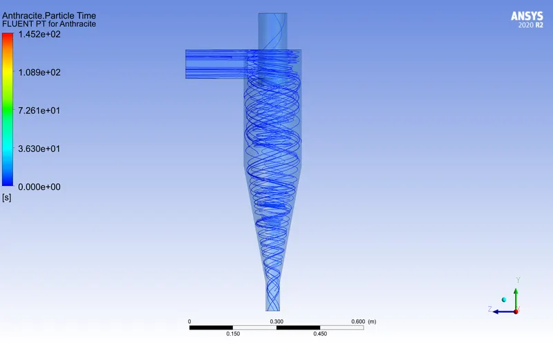
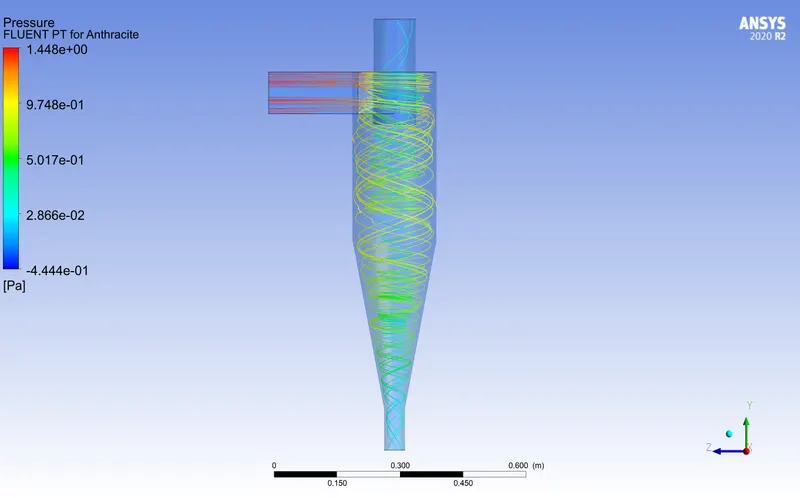
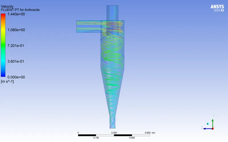
1m/s : number tracked = 124, escaped = 11, trapped = 6, incomplete = 107
Residence Time:
Pressure:
Velocity:
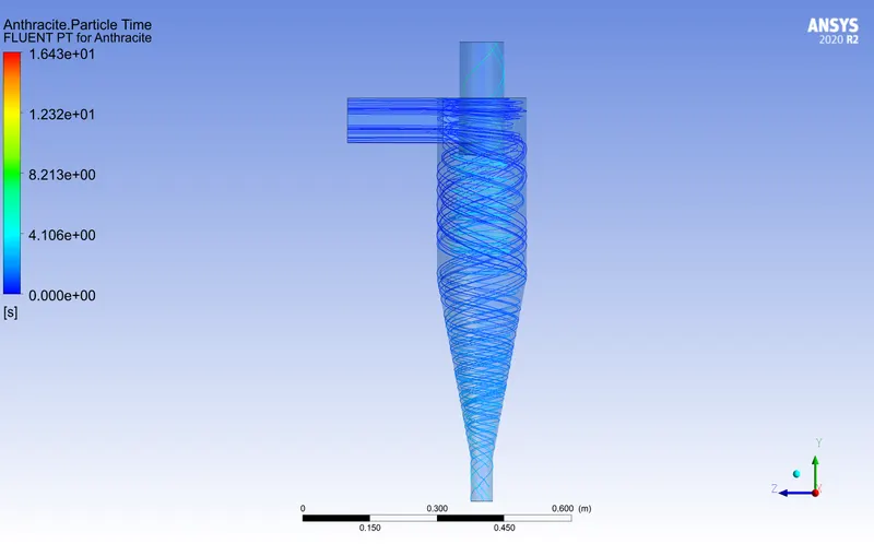
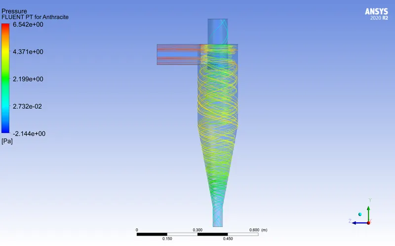
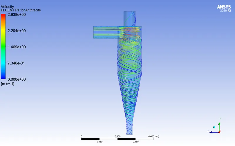
2m/s : number tracked = 124, escaped = 11, trapped = 27, incomplete = 86
Pressure:
Velocity:
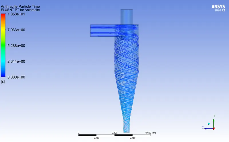
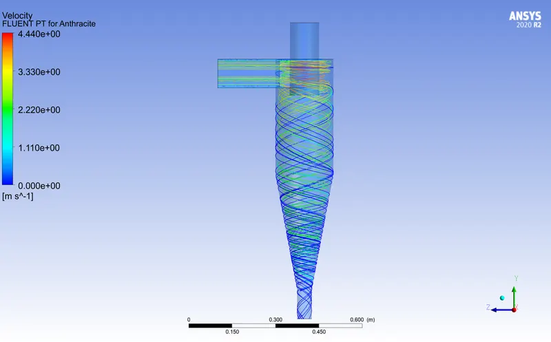
3m/s : number tracked = 124, escaped = 2, trapped = 86
Residence Time:
Pressure:
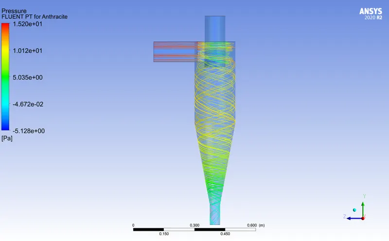
Velocity:
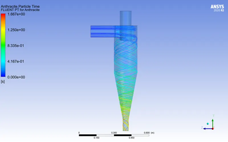
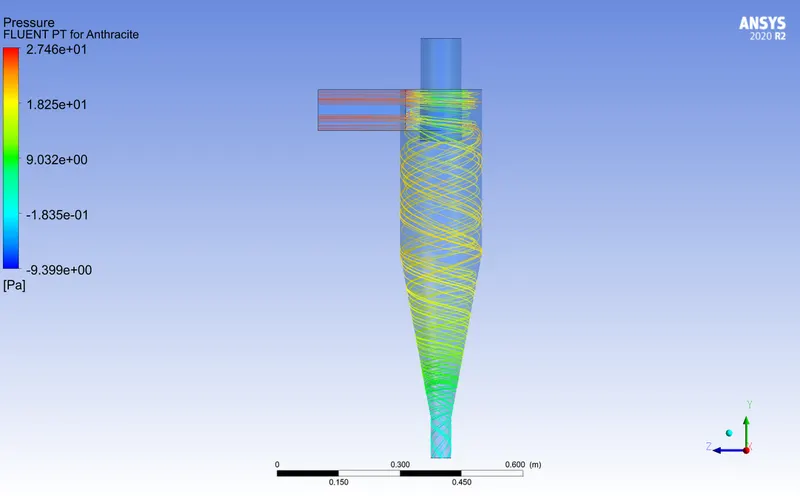
4m/s : number tracked = 124, trapped = 124
Residence Time:
Pressure:
Velocity:
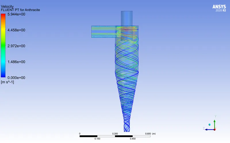
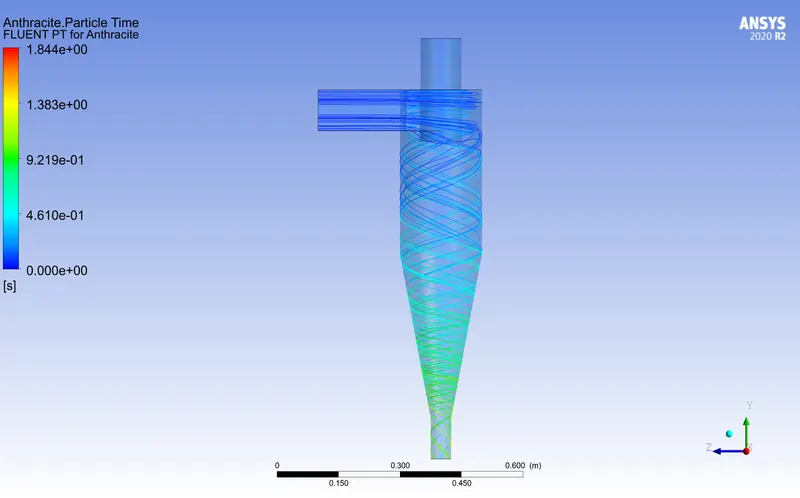
5m/s : number tracked = 124, trapped = 124
Residence Time:
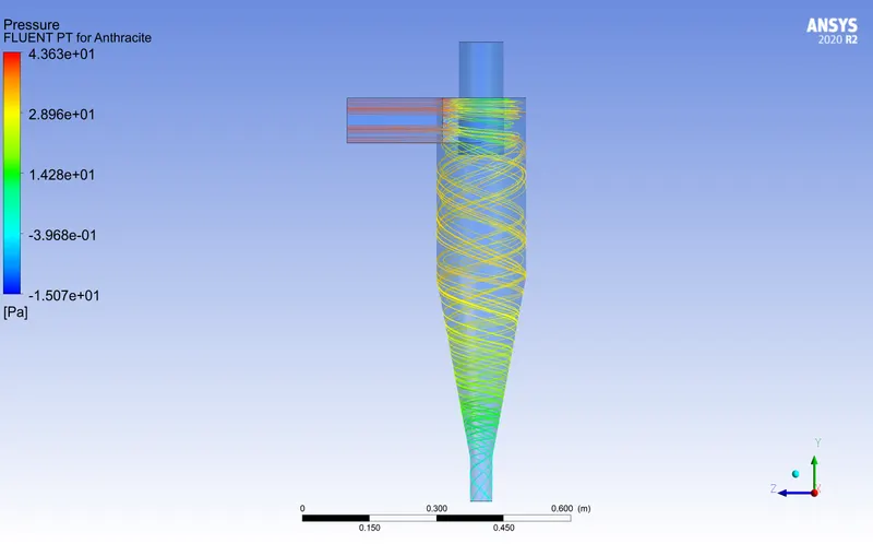
Pressure:
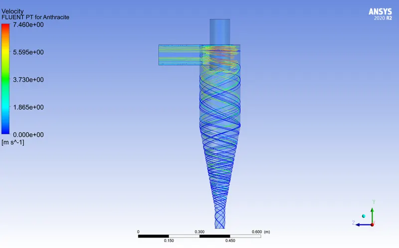
Velocity:
Inferences:
| Velocity m/s | Tracked | Trapped | Escaped | Efficiency % | Residence Time s | Velocity m/s | Pressure Difference Pa |
| 1 | 124 | 6 | 11 | 4.8 | 145.2 | 1.44 | 1.88 |
| 2 | 124 | 27 | 11 | 21.7 | 16.43 | 2.93 | 8.68 |
| 3 | 124 | 86 | 2 | 69.3 | 10.58 | 4.44 | 20.32 |
| 4 | 124 | 124 | 0 | 100 | 1.66 | 5.94 | 36.85 |
| 5 | 124 | 124 | 0 | 100 | 1.84 | 7.46 | 58.7 |
- It can be observed that the efficiency of particles being trapped increases as the velocity increases. This is due to the fact that with the increase of velocity, pressure difference increases, allowing more particles to be trapped.
- Also, it is to be noted that the residence time of particles also decreases drastically with an increase in velocity.
References:
[1]A CFD Study on the Prediction of Cyclone Collection Efficiency, Jolius Gimbun et al, International Journal for Computational Methods in Engineering Science and Mechanics · May 2005