Week 9: Project 1 - Surface preparation and Boundary Flagging (PFI)
Surface preparation and Boundary Flagging of Port Fuel Injection(PFI) Geometry
Objectives:
Perform a surface preparation on the Gasoline Engine PFI geometry and flag the necessary boundaries so as to perform CFD simulation.
Port Fuel Injection geometry:
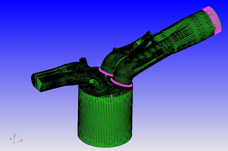
Fig (a). Port Fuel Injection geometry
- The above geometry consists of the engine combustion chamber with inlet and outlet ports.
- In Converge tool, each surface is represented as triangles which are visible in the above image. Apart from this, the regions which are highlighted in pinkish shade represent the errors at the surface level.
- Using an in-built diagnosis tool below errors were detected.
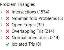
Intersections:
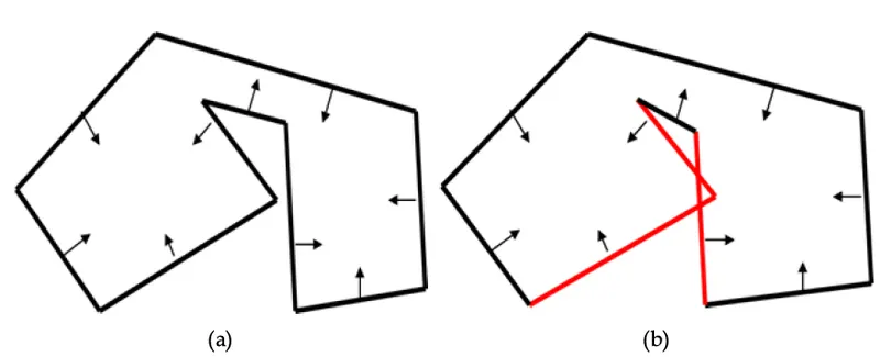
Intersections are interferences between two surfaces that cross each other at any angle. An intersection would violate the concept of a consistent inside/outside orientation of the surface.
Here, in the below image, surfaces of intake valves and surfaces of the cylinder head are intersecting each other which is highlighted in red color.
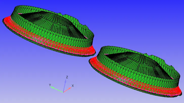
Fig (b). Intersecting triangles
Non-manifold problems:
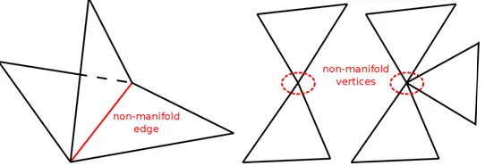
A non-manifold geometry is a 3D shape that cannot be unfolded into a 2D surface with all its normals pointing in the same direction. In other words, if more than two triangles share a common edge, it forms a T-junction, this edge is a nonmanifold edge.
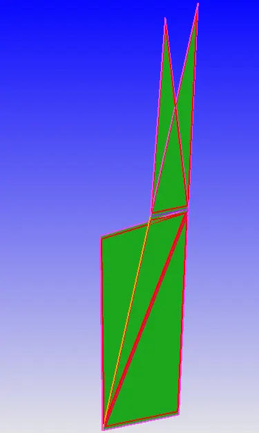
Fig (c) Left: examples of non-manifold geometries, Right: non-manifold surfaces at the cylinder head
In the above figure (c), several triangular surfaces are overlapping at inconsistent vertices leading to non-manifold error.
Open Edges:
As the name suggests, open edges are literally triangular surfaces that do not share all of their boundaries with another triangular surface to form a closed volume. If an edge is part of only one triangle, that edge is called an open edge.
Below figure (d), illustrates the same which was detected on the face of the piston.
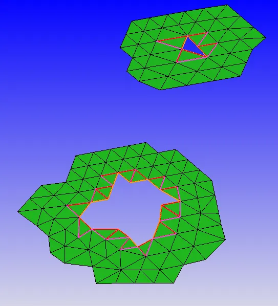
Fig (d) Open edges
Overlapping Trias:
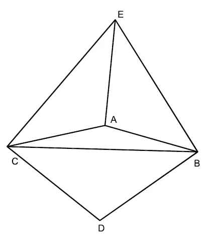
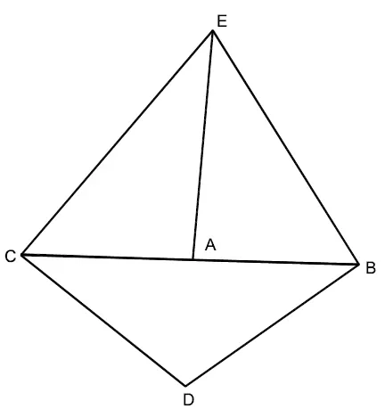
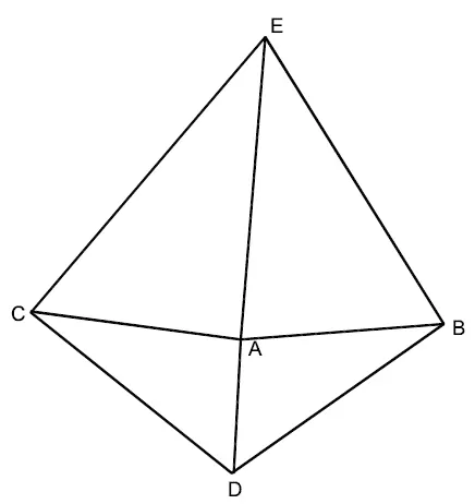
Fig (e) In left geometry, triangles AEC, ABE, ACB, and BCD, with all of their normal vectors pointing out of the page and it is considered properly triangulated. In middle geometry, if vertex A is located on segment BC, then vertices A, B, and C are collinear and thus triangle ABC has zero area. This zero-area triangle will have a random normal vector which causes error. Repairing these triangles by moving (translating) vertex A, stitching A to B or C, or retriangulating the system creates triangles ABE, AEC, ACD, and ADB which is acceptable.
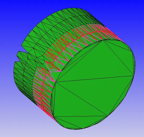
Fig. (f) overlapping trias
In the above figure, overlapping trias are present at the inlet port. This is fixed using the inbuilt tools of Converge which removes the overlapping trias.
Normal Orientation:
CONVERGE requires the surface to have a properly defined inside (solved fluid side) and outside (non-fluid side). The normal vectors of all triangles (as defined by the right-hand rule) must point toward the fluid.
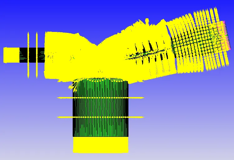
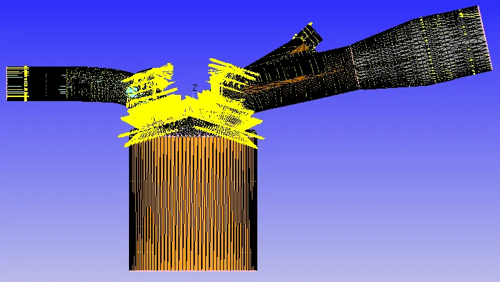
Fig. (g) Normals pointing outwards (left), Normals pointing inwards (right)
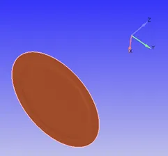
Piston:
The above figure shows the piston face which reciprocates to compress the air-fuel mixture and initiate combustion.
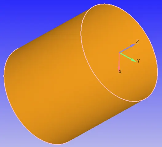
Liner:
The liner geometry is the region through which the piston face reciprocates. In other terms, liner forms the basis of a combustion chamber.
Cylinder head:
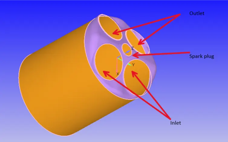
The cylinder head consists of ports such as a fuel inlet, exhaust outlet, and spark plug. They are located on top of the liner perpendicular to the reciprocating motion of the piston face.
Intake and exhaust valves:
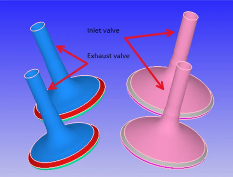
Inlet and exhaust valves facilitate the intake of air-fuel mixture and expel exhaust emissions. They work based on a timing cycle. When the piston moves to the BDC, the inlet valves open, and when the piston moves to TDC initiates combustion thereby exhaust valves open to push out emissions.
Spark plug terminal:
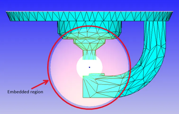
The above figure shows the embedded region around the spark plug terminal. The embedded region is formed in order to model the spark accurately which initiates combustion when the air-fuel mixture comes into contact.
Intake region:
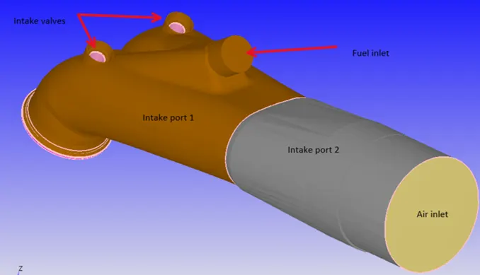
Two different regions intake ports 1 and 2 are defined separately in order to assign initial conditions separately. Fuel inlet and air inlet and located at different points with different sizes.
Exhaust/Outlet region:
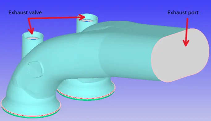
Similar to inlet regions facilitating the flow of air-fuel mixture, the exhaust port facilitates the removal of emissions post-combustion.
Simulation Setup:
In Converge Studio GUI, a Crank angle-based simulation is set up which sets up the case suitable for engine simulation.
Engine Geometric Parameters:
1. Bore =0.086 m
2. Stroke = 0.09 m
3. Connecting rod length = 0.18 m
4. RPM = 3000
Run Parameters:
- Gas Simulation - ON
- Simulation Type-Transient
- Mode - No Hydrodynamic Solver (Used for testing the case setup)
- Solver - PISO density-based
- Turbulence Model - RNG k-epsilon
- Start time: -520 deg, End time: 120 deg
Boundary conditions:
1. Piston temperature - 450K
2. Liner temperature - 450K
3. Head temperature - 450K
4. Spark Plug temperature - 550K
5. Spark Plug electrode temperature - 600K
6. Exhaust ports temperature - 500K
7. Exhaust outflow - 1 bar
8. Exhaust outflow temperature - 800k
9. Exhaust species concentration - Calculate the stoichiometric condition
10. Exhaust valve top temperature - 525K
11. Exhaust valve angle temperature - 525K
12. Exhaust valve bottom temperature - 525K
13. Intake port - 1 temperature 425K
14. Intake port - 2 temperature 425K
15. Inflow pressure - 1 bar total pressure
16. Inflow temperature - 363K
17. Inflow species - Air
18. Intake valve top temperature - 480K
19. Intake valve angle temperature - 480K
20. Intake valve bottom temperature - 480K
Initial conditions:
- Intake port - 1 (closer to combustion chamber)
o ic8h18 - 0.025508
o o2 - 0.20157
o n2 - 0.77292
o Temperature - 390k
o pressure - 1 bar - Intake port - 2 (away from combustion chamber)
o Air
o Temperature - 370K
o Pressure - 1 bar - Cylinder
o Pressure - 1.85731 bar
o Temperature - 1360K
o Stoichiometric composition
Events:
Events are assigned to perform certain actions such as movement of boundary (eg. rupture of diaphragm, reciprocating of the piston, valves, etc at a specific time period.) Creating different regions helps to assign events.

The above event is cyclic which is assigned to Intake and Exhaust valve movements at specified Crank angles.

Intake ports 1 and 2 facilitating intake of air and fuel is set to a permanent event as open.
Grid Generation:
A baseline grid of 0.004m along all 3 directions is generated.
Result:
References:
[1] Converge 3.0 Manual