Week 8 - BlockMesh Drill down challenge
BlockMesh Drill Down Challenge
Aim:
- Create a simple geometry and mesh the same using blockmesh
- How does the velocity magnitude profile change as a function of mesh grading factor. Use factors, 0.2, 0.5,0.8
- Measure the velocity profile at 0.085 m from the inlet of the geometry
- Plot must be a line plot
- Compare velocity magnitude contours near the step region for the above mentioned grading factors.
Given Data:
- Number of cells along the x direction (longer dimension) = 200
- Number of cells along the y direction = 10
- Use a graded mesh. Grading factor near all walls should be 0.2 and then 0.5,0.8.
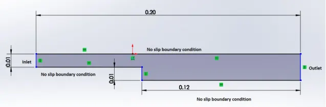
Solution:
The flow which we are going to simulate is incompressible flow for which OpenFOAM offers several solvers such as simpleFoam, icoFoam, pisoFoam etc.
The solver used here is icofoam which is a transient , incompressible, laminar flow solver.
1. Editing the blockMesh file
- Assignment of nodes/vertices:
The above given geometry is created by altering the vertices of the blockmesh file under incompressible flow tutorial.
The geometry is divided into 5 blocks and the vertices of first face consists of 11 vertices.
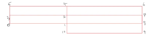
The vertices are as follows;
    (0 0 0) //0
    (0.08 0 0) //1
    (0.08 0.005 0) //2
    (0 0.005 0) //3
    (0.08 0.01 0) //4
    (0 0.01 0)//5
    (0.20 0.01 0)//6
    (0.20 0.005 0)//7
    (0.2 0 0)  //8
    (0.2 -0.01 0)  //9
    (0.08 -0.01 0) //10
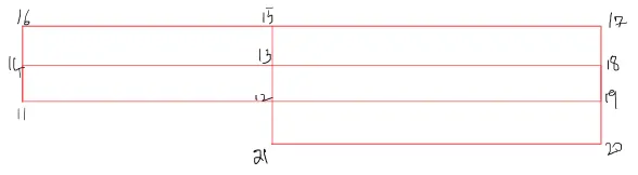
Above image shows the vertices used to represent the geometry as 3D.
The vertices are as follows;
    (0 0 0.02) //11
    (0.08 0 0.02) //12
    (0.08 0.005 0.02) //13
    (0 0.005 0.02) //14
    (0.08 0.01 0.02) //15
    (0 0.01 0.02)//16
    (0.20 0.01 0.02)//17
    (0.20 0.005 0.02)//18
    (0.2 0 0.02)  //19
    (0.2 -0.01 0.02)  //20
    (0.08 -0.01 0.02) //21
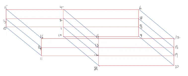
Joining the two sets of vertices represented above creates the below geometry;
- Conversion of nodes/vertices into blocks:
Now, the vertices are converted into 5 blocks as shown in the below image. Blocks are named by taking the vertices in clockwise direction while seen from inside.
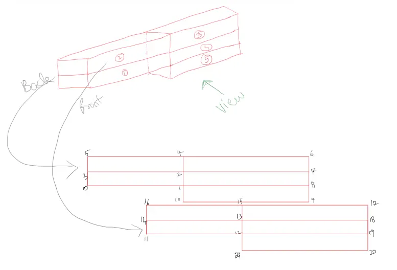
Below lines shows the 5 blocks formed by the vertices. The second bracket represents the number of nodes along x,y,z direction. simpleGrading is used for refinement of mesh along the three directions.
SimpleGrading:
It is the ratio of length of last cell to the first cell measured from the left bottom corner of every block along respective directions.
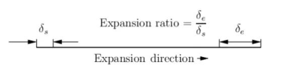
In our challenge, 0.2,0.5,0.8 are the required grading factors near the walls.
Totally there are five blocks with the following dimensions,
block 1 and 2 are of length = 0.08m along x axis and 0.005m along y axis.
block 2 and 3 are of length = 0.12m along x axis and 0.005m along y axis
block 5 is of length = 0.12m along x axis and 0.01m along y axis
Note:All the values along x axis are divided by 200 nodes and along y axis by 10 nodes which gives the even cell spacing of blocks.
The left bottom corner of a block is always considered to be the origin or reference point.
For 0.2 Grading Factor:
Along x axis, applicable to block 1 and 2:
cell size along x = 0.4mm and let 0.4 be the cell size at the end of x axis
0.4/?=0.2 =>2, Now 2mm is the size of cell at the start of x axis.
The reversal of the same (i.e., 2/0.4)will yield a grading value of 5
Along x axis, applicable to block 3,4 and 5:
cell size along x = 0.6mm and let 0.6 be the cell size at the end of x axis
0.6/?=0.2 =>3, Now 3mm is the size of cell at the start of x axis.
The reversal of the same (i.e., 3/0.6)will yield a grading value of 5
Along y axis , applicable to block 1,2,3 and 4:
cell size along y = 0.5mm and let 0.5 be the cell size at the end of y axis
0.5/?=0.2 =>2.5, Now 3mm is the size of cell at the start of y axis.
The reversal of the same (i.e., 2.5/0.5)will yield a grading value of 5
Along y axis , applicable to block 5:
cell size along y = 1mm and let 1 be the cell size at the end of y axis
1/?=0.2 =>5, Now 5mm is the size of cell at the start of y axis.
The reversal of the same (i.e., 5/1)will yield a grading value of 5.
Now it is clear that the value of 0.2 and 5 should be used to locate the fine mesh along the desired region of the geometry(wall).
In short note, the max value 5 denotes that the mesh will be fine at the start of the respective axis and the min value 0.2 denotes that the mesh will be coarse at the start of the respective axis.
Block script for 0.2 Grading factor:
blocks
(
    hex (0 1 2 3 11 12 13 14) (200 10 1) simpleGrading (5 5 1)

    hex (3 2 4 5 14 13 15 16) (200 10 1) simpleGrading (5 0.2 1)

    hex (2 7 6 4 13 18 17 15) (200 10 1) simpleGrading (0.2 0.2 1)

    hex (1 8 7 2 12 19 18 13) (200 10 1) simpleGrading (0.2 5 1)

    hex (10 9 8 1 21 20 19 12) (200 10 1) simpleGrading (0.2 5 1)

);
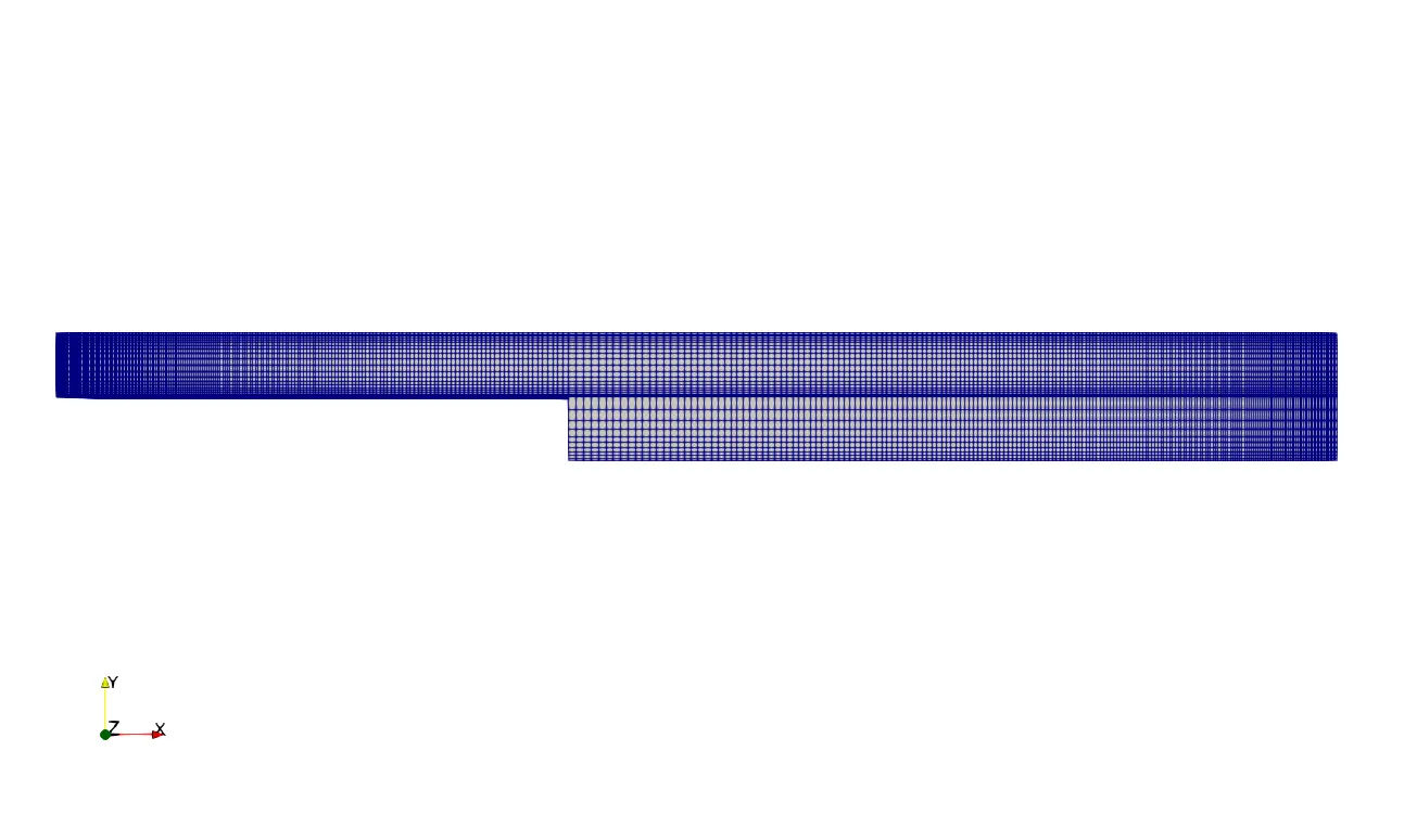
Resulted mesh for 0.2 Grading factor:
For 0.5 Grading Factor:
Along x axis, applicable to block 1 and 2:
cell size along x = 0.4mm and let 0.4 be the cell size at the end of x axis
0.4/?=0.5 =>0.8, Now 0.8mm is the size of cell at the start of x axis.
The reversal of the same (i.e., 0.8/0.4)will yield a grading value of 2
Along x axis, applicable to block 3,4 and 5:
cell size along x = 0.6mm and let 0.6 be the cell size at the end of x axis
0.6/?=0.5 =>1.2, Now 1.2mm is the size of cell at the start of x axis.
The reversal of the same (i.e., 1.2/0.6)will yield a grading value of 2
Along y axis , applicable to block 1,2,3 and 4:
cell size along y = 0.5mm and let 0.5 be the cell size at the end of y axis
0.5/?=0.5=>1, Now 1mm is the size of cell at the start of y axis.
The reversal of the same (i.e., 1/0.5)will yield a grading value of 2
Along y axis , applicable to block 5:
cell size along y = 1mm and let 1 be the cell size at the end of y axis
1/?=0.5 =>2, Now 2mm is the size of cell at the start of y axis.
The reversal of the same (i.e., 2/1)will yield a grading value of 2.
Now it is clear that the value of 0.5 and 2 should be used to locate the fine mesh along the desired region of the geometry(wall).
In short note, the max value 2 denotes that the mesh will be fine at the start of the respective axis and the min value 0.5 denotes that the mesh will be coarse at the start of the respective axis.
Block script for 0.5 Grading factor:
blocks
(
    hex (0 1 2 3 11 12 13 14) (200 10 1) simpleGrading (2 2 1)

    hex (3 2 4 5 14 13 15 16) (200 10 1) simpleGrading (2 0.5 1)

    hex (2 7 6 4 13 18 17 15) (200 10 1) simpleGrading (0.5 0.5 1)

    hex (1 8 7 2 12 19 18 13) (200 10 1) simpleGrading (0.5 2 1)

    hex (10 9 8 1 21 20 19 12) (200 10 1) simpleGrading (0.5 2 1)

);
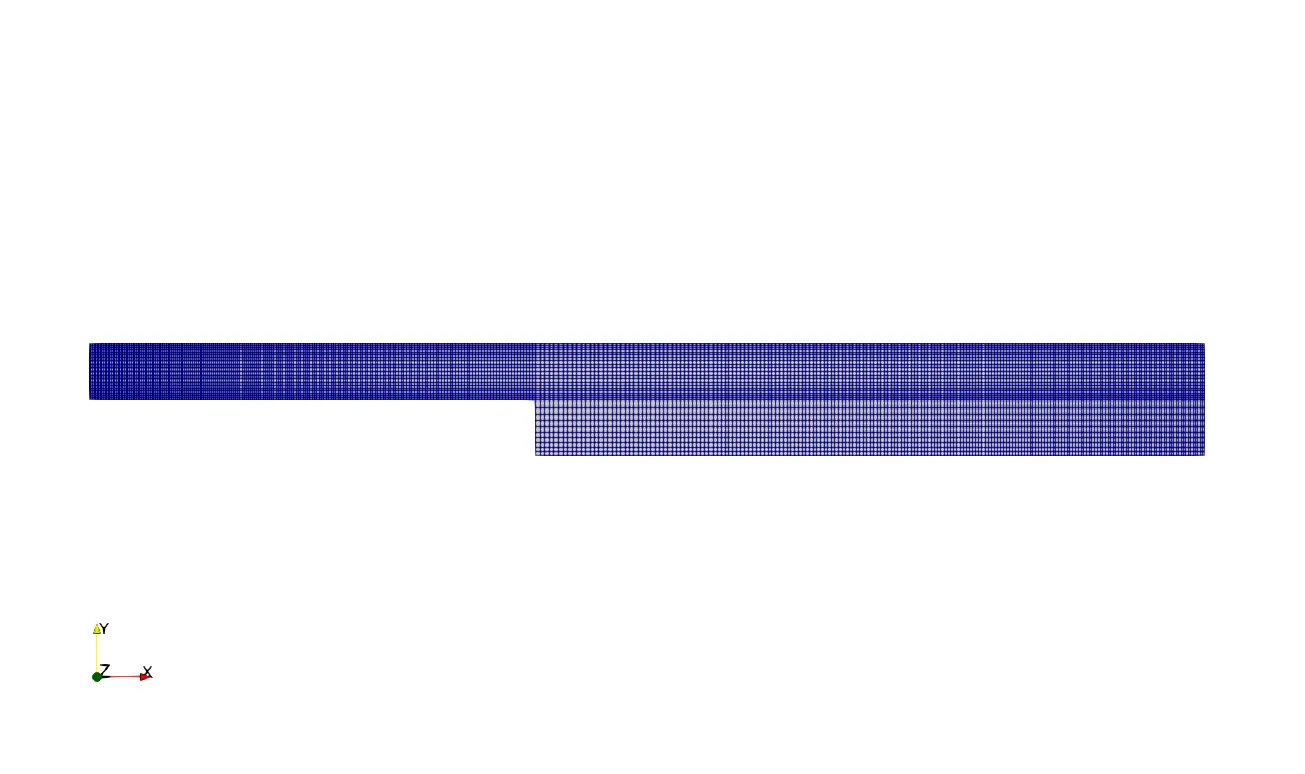
Resulted mesh for 0.5 Grading Factor:
For 0.8 Grading Factor:
Along x axis, applicable to block 1 and 2:
cell size along x = 0.4mm and let 0.4 be the cell size at the end of x axis
0.4/?=0.8 =>0.5, Now 0.5mm is the size of cell at the start of x axis.
The reversal of the same (i.e., 0.5/0.4)will yield a grading value of 1.25
Along x axis, applicable to block 3,4 and 5:
cell size along x = 0.6mm and let 0.6 be the cell size at the end of x axis
0.6/?=0.8 =>0.75, Now 0.75mm is the size of cell at the start of x axis.
The reversal of the same (i.e., 0.75/0.6)will yield a grading value of 1.25
Along y axis , applicable to block 1,2,3 and 4:
cell size along y = 0.5mm and let 0.5 be the cell size at the end of y axis
0.5/?=0.8=>0.625, Now 0.625mm is the size of cell at the start of y axis.
The reversal of the same (i.e., 0.625/0.5)will yield a grading value of 1.25
Along y axis , applicable to block 5:
cell size along y = 1mm and let 1 be the cell size at the end of y axis
1/?=0.8 =>1.25, Now 1.25mm is the size of cell at the start of y axis.
The reversal of the same (i.e., 1.25/1)will yield a grading value of 1.25
Now it is clear that the value of 0.8 and 1.25 should be used to locate the fine mesh along the desired region of the geometry(wall).
In short note, the max value 1.25 denotes that the mesh will be fine at the start of the respective axis and the min value 0.8 denotes that the mesh will be coarse at the start of the respective axis.
Block script for 0.8 Grading factor:
blocks
(
    hex (0 1 2 3 11 12 13 14) (200 10 1) simpleGrading (1.25 1.25 1)

    hex (3 2 4 5 14 13 15 16) (200 10 1) simpleGrading (1.25 0.8 1)

    hex (2 7 6 4 13 18 17 15) (200 10 1) simpleGrading (0.8 0.8 1)

    hex (1 8 7 2 12 19 18 13) (200 10 1) simpleGrading (0.8 1.25 1)

    hex (10 9 8 1 21 20 19 12) (200 10 1) simpleGrading (0.8 1.25 1)

);
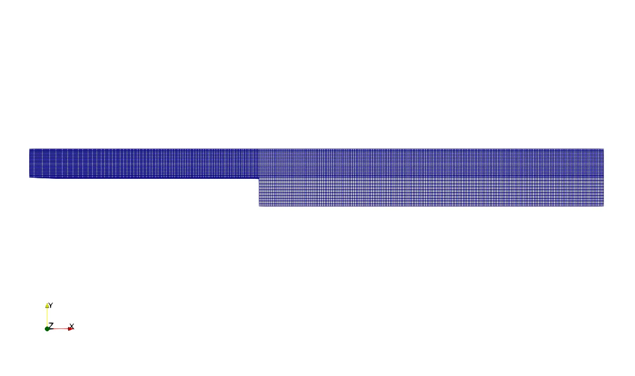
Resulted mesh for 0.8 Grading Factor:
- Assignment of boundaries:
Now the boundaries are organised as per the below images;
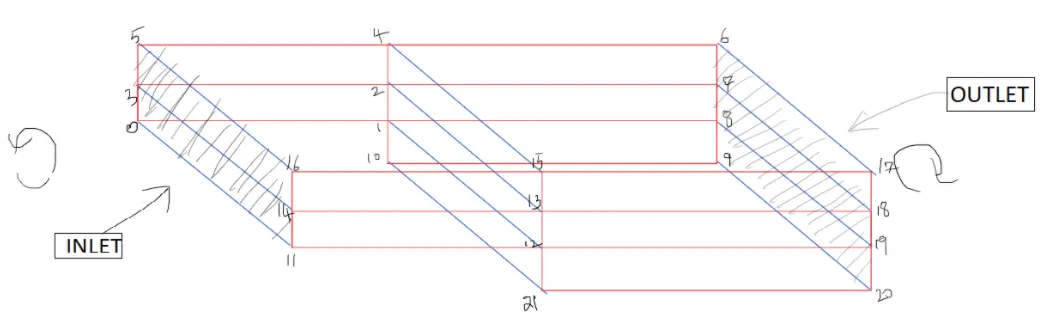
inlet
    {
        type patch;
        faces
        (
            (0 11 14 3)
            (3 14 16 5)

        );
    }
    outlet
    {
        type patch;
        faces
        (
            (9 8 19 20)
            (8 7 18 19)
            (7 6 17 18)
        );
    }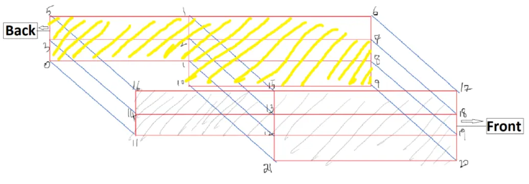
frontAndBack
    {
        type empty;
        faces
        (
            (0 1 2 3)
            (3 2 4 5)
            (2 7 6 4)
            (1 8 7 2)
            (10 9 8 1)
            (11 12 13 14)
            (14 13 15 16)
            (13 18 17 15)
            (12 19 18 13)
            (21 20 19 12)
        );
    }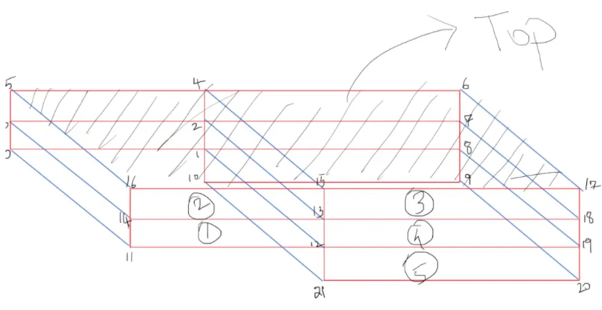
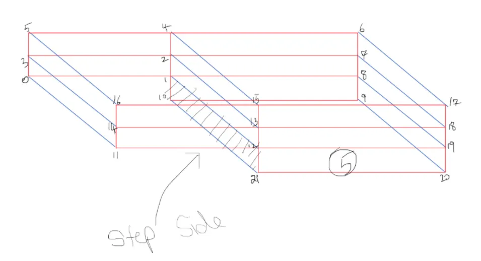
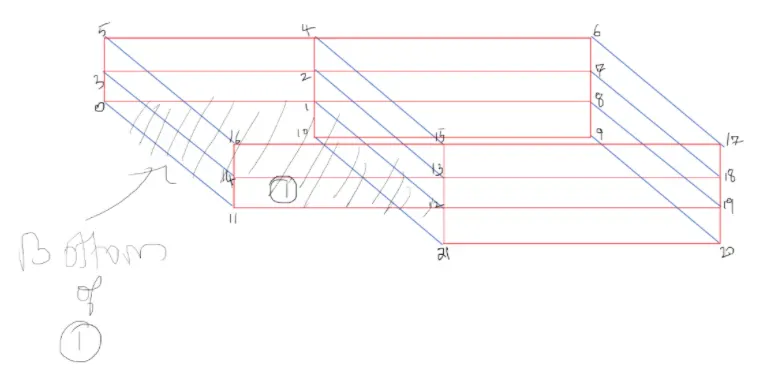
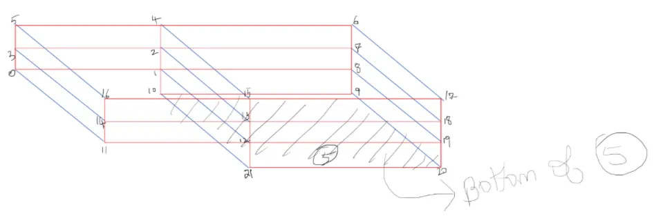
All the above top and bottom faces are represented by the following set of code lines;
    upperWall
    {
        type wall;
        faces
        (
            (16 15 4 5)
            (15 17 6 4)
        );
    }
    lowerWall
    {
        type wall;
        faces
        (
            (11 12 1 0)
            (21 12 1 10)
            (21 20 9 10)

        );
    }
Complete Program of blockMeshDict:
/*--------------------------------*- C++ -*----------------------------------*\
  =========                 |
  \\      /  F ield         | OpenFOAM: The Open Source CFD Toolbox
   \\    /   O peration     | Website:  https://openfoam.org
    \\  /    A nd           | Version:  8
     \\/     M anipulation  |
\*---------------------------------------------------------------------------*/
FoamFile
{
    version     2.0;
    format      ascii;
    class       dictionary;
    object      blockMeshDict;
}
// * * * * * * * * * * * * * * * * * * * * * * * * * * * * * * * * * * * * * //

// Note: this file is a Copy of $FOAM_TUTORIALS/resources/blockMesh/pitzDaily

convertToMeters 1;

vertices
(
    (0 0 0) //0
    (0.08 0 0) //1
    (0.08 0.005 0) //2
    (0 0.005 0) //3
    (0.08 0.01 0) //4
    (0 0.01 0)//5
    (0.20 0.01 0)//6
    (0.20 0.005 0)//7
    (0.2 0 0)  //8
    (0.2 -0.01 0)  //9
    (0.08 -0.01 0) //10

    (0 0 0.02) //11
    (0.08 0 0.02) //12
    (0.08 0.005 0.02) //13
    (0 0.005 0.02) //14
    (0.08 0.01 0.02) //15
    (0 0.01 0.02)//16
    (0.20 0.01 0.02)//17
    (0.20 0.005 0.02)//18
    (0.2 0 0.02)  //19
    (0.2 -0.01 0.02)  //20
    (0.08 -0.01 0.02) //21


);


blocks
(
    hex (0 1 2 3 11 12 13 14) (200 10 1) simpleGrading (5 5 1)

    hex (3 2 4 5 14 13 15 16) (200 10 1) simpleGrading (5 0.2 1)

    hex (2 7 6 4 13 18 17 15) (200 10 1) simpleGrading (0.2 0.2 1)

    hex (1 8 7 2 12 19 18 13) (200 10 1) simpleGrading (0.2 5 1)

    hex (10 9 8 1 21 20 19 12) (200 10 1) simpleGrading (0.2 5 1)

);

edges
(
);

boundary
(
    inlet
    {
        type patch;
        faces
        (
            (0 11 14 3)
            (3 14 16 5)

        );
    }
    outlet
    {
        type patch;
        faces
        (
            (9 8 19 20)
            (8 7 18 19)
            (7 6 17 18)
        );
    }
    upperWall
    {
        type wall;
        faces
        (
            (16 15 4 5)
            (15 17 6 4)
        );
    }
    lowerWall
    {
        type wall;
        faces
        (
            (11 12 1 0)
            (21 12 1 10)
            (21 20 9 10)

        );
    }
    frontAndBack
    {
        type empty;
        faces
        (
            (0 1 2 3)
            (3 2 4 5)
            (2 7 6 4)
            (1 8 7 2)
            (10 9 8 1)
            (11 12 13 14)
            (14 13 15 16)
            (13 18 17 15)
            (12 19 18 13)
            (21 20 19 12)
        );
    }
);

// ************************************************************************* //
Controldict file:
This file handles all the computation setup such as start and end time, time step and the writing intervals along with the format required.
- CFL condition:
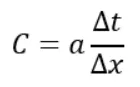
Here, C is the courant number which is dimensionless. a is the initial velocity, dt is the time step, dx is the distance between the nodes. The value of C must be less than or equal to 1.
In our case, the mesh is not uniform. I have taken time step based out of max value of dx which would occure for the different grading factor which was discussed above.
Therefore the initial velocity is set to 1 m/s , max dx for 0.2 grading is 0.005m, and dt = 0.000005=>C=0.001
max dx for 0.5 grading is 0.002 and dt = 0.000005=>C=0.0025
max dx for 0.8 grading is 0.00125 and dt=0.000005=>C=0.004
Controldict program:
/*--------------------------------*- C++ -*----------------------------------*\
  =========                 |
  \\      /  F ield         | OpenFOAM: The Open Source CFD Toolbox
   \\    /   O peration     | Website:  https://openfoam.org
    \\  /    A nd           | Version:  8
     \\/     M anipulation  |
\*---------------------------------------------------------------------------*/
FoamFile
{
    version     2.0;
    format      ascii;
    class       dictionary;
    location    "system";
    object      controlDict;
}
// * * * * * * * * * * * * * * * * * * * * * * * * * * * * * * * * * * * * * //

application     icoFoam;

startFrom       startTime;

startTime       0;

stopAt          endTime;

endTime         0.1;

deltaT          0.000005;

writeControl    timeStep;

writeInterval   200;

purgeWrite      0;

writeFormat     ascii;

writePrecision  6;

writeCompression off;

timeFormat      general;

timePrecision   6;

runTimeModifiable true;


// ************************************************************************* //
Pressure file (P):
This file contains the initial boundary conditions for pressure.
/*--------------------------------*- C++ -*----------------------------------*\
  =========                 |
  \\      /  F ield         | OpenFOAM: The Open Source CFD Toolbox
   \\    /   O peration     | Website:  https://openfoam.org
    \\  /    A nd           | Version:  8
     \\/     M anipulation  |
\*---------------------------------------------------------------------------*/
FoamFile
{
    version     2.0;
    format      ascii;
    class       volScalarField;
    object      p;
}
// * * * * * * * * * * * * * * * * * * * * * * * * * * * * * * * * * * * * * //

dimensions      [0 2 -2 0 0 0 0];

internalField   uniform 0;

boundaryField
{
    inlet
    {
        type            zeroGradient;
    }

    outlet
    {
        type            fixedValue;
        value           uniform 0;
    }
    upperWall
    {
        type            zeroGradient;
    }
    lowerWall
    {
        type            zeroGradient;
    }

    frontAndBack
    {
        type            empty;
    }
}

// ************************************************************************* //
Velocity file (U):
This file contains the initial velocity data for the simulations to proceed with. Here, the initial velocity is 1 m/s.
/*--------------------------------*- C++ -*----------------------------------*\
  =========                 |
  \\      /  F ield         | OpenFOAM: The Open Source CFD Toolbox
   \\    /   O peration     | Website:  https://openfoam.org
    \\  /    A nd           | Version:  8
     \\/     M anipulation  |
\*---------------------------------------------------------------------------*/
FoamFile
{
    version     2.0;
    format      ascii;
    class       volVectorField;
    object      U;
}
// * * * * * * * * * * * * * * * * * * * * * * * * * * * * * * * * * * * * * //

dimensions      [0 1 -1 0 0 0 0];

internalField   uniform (0 0 0);

boundaryField
{
    inlet
    {
        type            fixedValue;
        value           uniform (1 0 0);
    }

    outlet
    {
        type            zeroGradient;
    }
    upperWall
    {
        type            fixedValue;
        value           uniform (0 0 0);
    }
    lowerWall
    {
        type            fixedValue;
        value           uniform (0 0 0);
    }

    frontAndBack
    {
        type            empty;
    }
}

// ************************************************************************* //
Results:
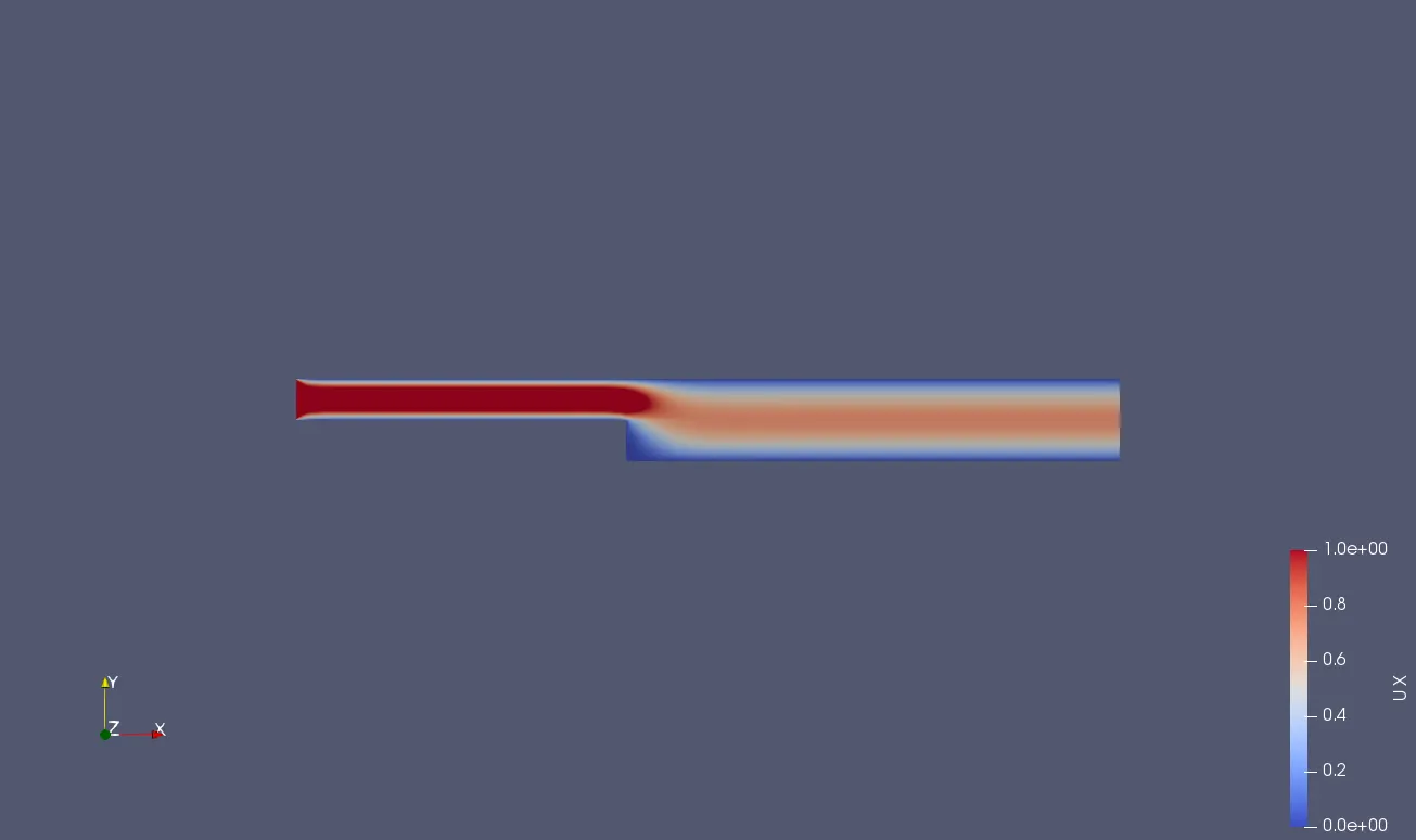
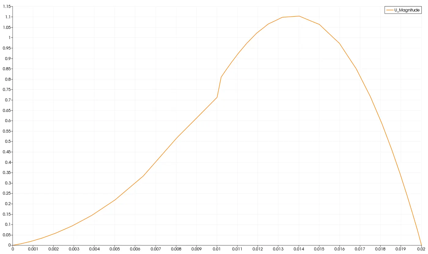
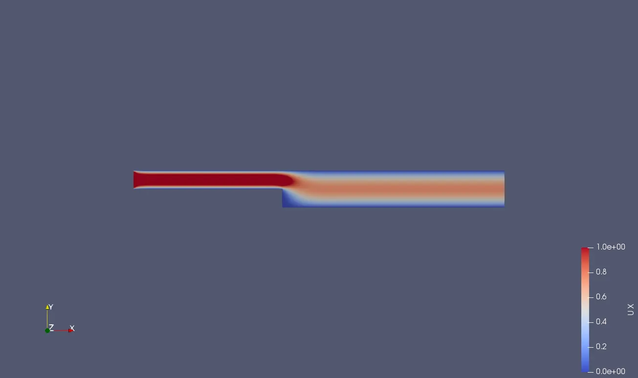
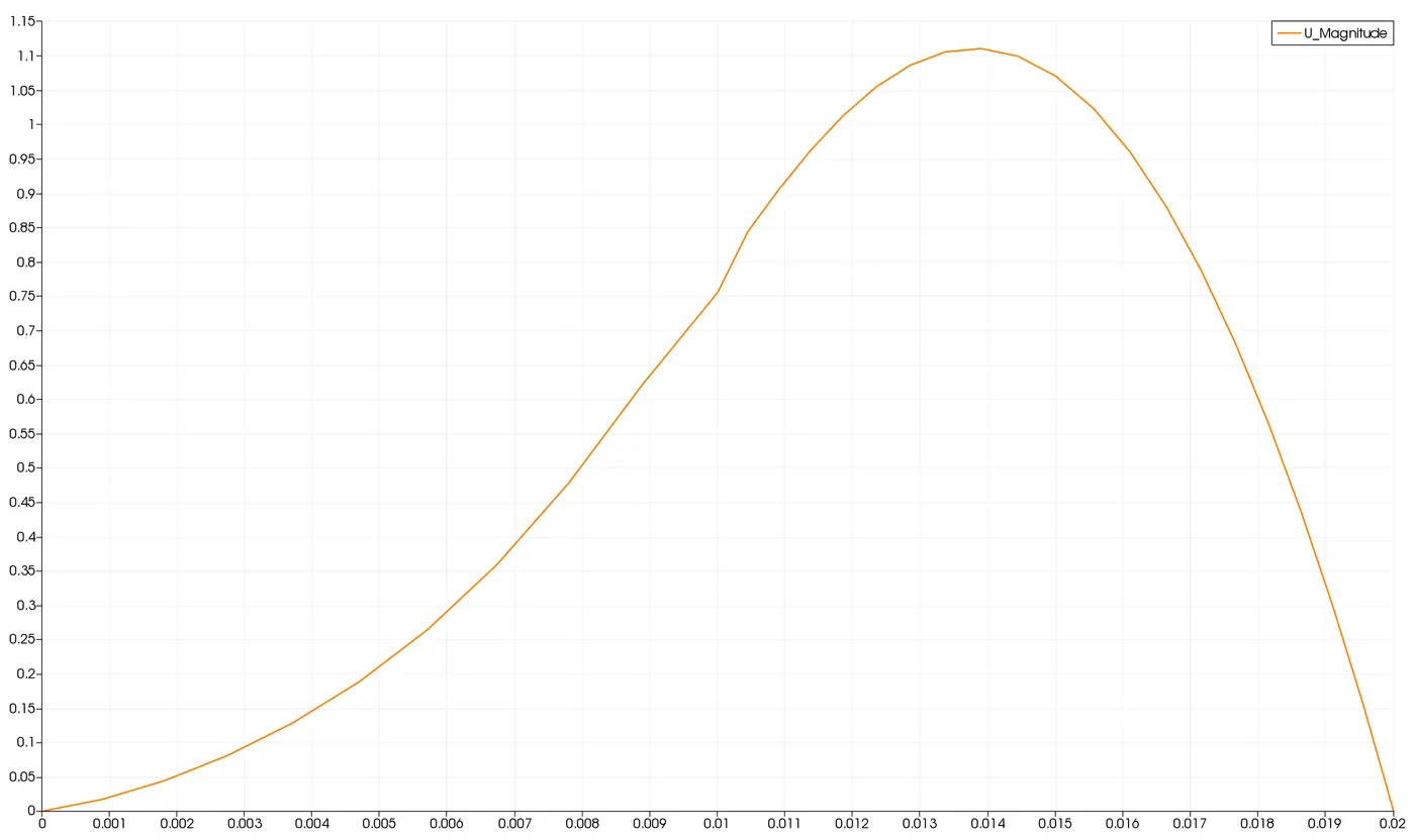
Profile at 0.085m distance from origin (0.2 Grading Factor)
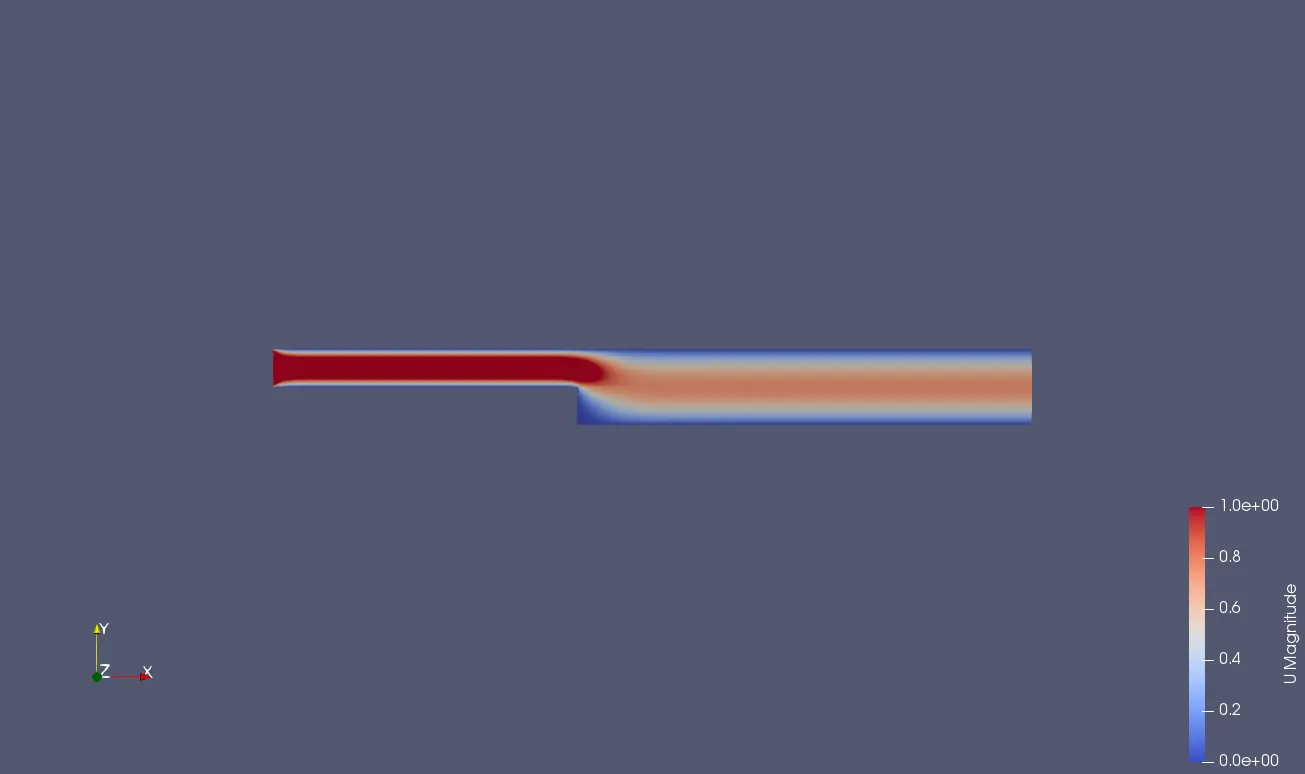
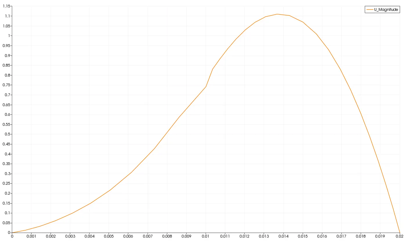
Profile at 0.085m distance from origin (0.5 Grading Factor)
Profile at 0.085m distance from origin (0.8 Grading Factor)
Inference:
- From the above profiles and plots for Grading factors 0.2, 0.5 and 0.8, there is not much deviation in the results when it is analysed visually.
- Technically, 0.2 Grading Factor along the walls should be a finer mesh compared to having 0.5 or 0.8. This means that the results should be more accurate in 0.2 Grading Factor
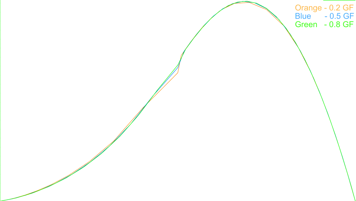
- The superimposed image shows the variation between the plots. At 0.075-0.085 m, there is a huge variation in terms of accuracy. Plots of grading factor 0.5 and 0.8 look way smoothened whereas 0.2 looks more accurate to the exact solution.
- This deviation of solution may result in loss of capturing exact vortex or flow vectors formed at that location.
- This proves that lower the grading higher the accuracy but at the cost of computation power.