Week-7 : Converting a detailed engine model to a FRM model
Converting a detailed engine model to a FRM model
Objectives:
- Convert a detailed engine model to FRM Model
- Build FRM Model for following configuration using FRM builder approach
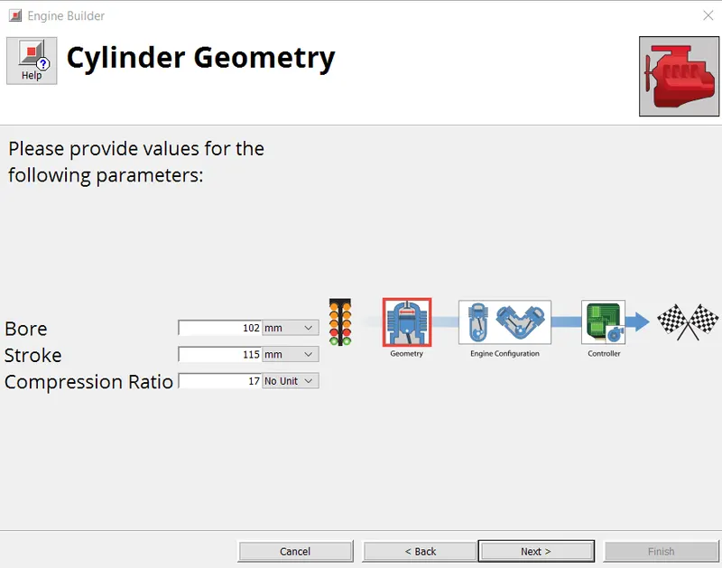
- Bore 102 mm stroke 115 mm CR 17
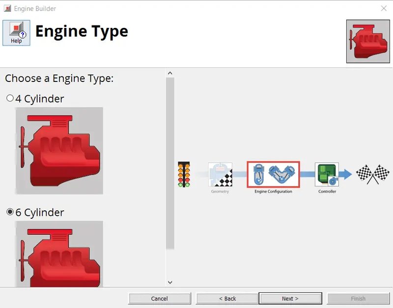
- No of cylinder 6
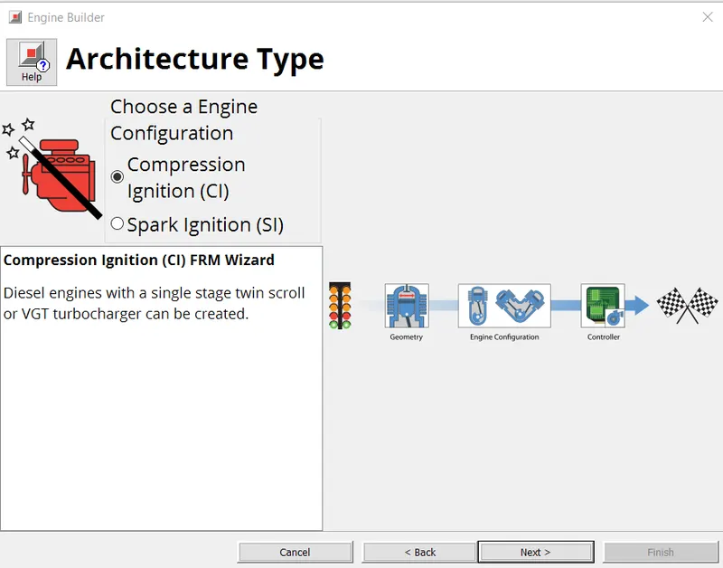
- CI engine
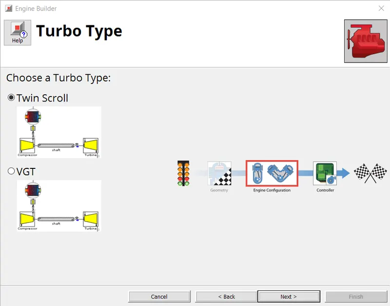
- Twin Scroll Turbine
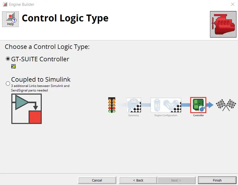
- GT Controller
Fast Running Model (FRM):
- FRMs execute much more rapidly than the typical detailed GT-POWER engine model, and are ideal for integrating with other vehicle systems where an accurate and predictive engine plant model is desired and where computational speed is critical.
- Fast Running Engine Models are dynamic, fully-physical engine models that are designed specifically to run fast.
- FRMs are able to achieve such fast run times by two means: (1) increasing the simulation time step size, and (2) decreasing the number of calculations per time step. These two means are often accomplished at the same time by lumping various flow volumes together which will reduce the total number of subvolumes and also allow for a larger time step size by increasing the effective subvolume length (which is responsible for the time step size).
Detailed SI Turbocharged Engine Model:
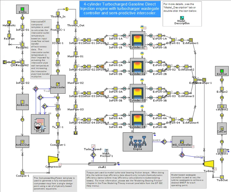
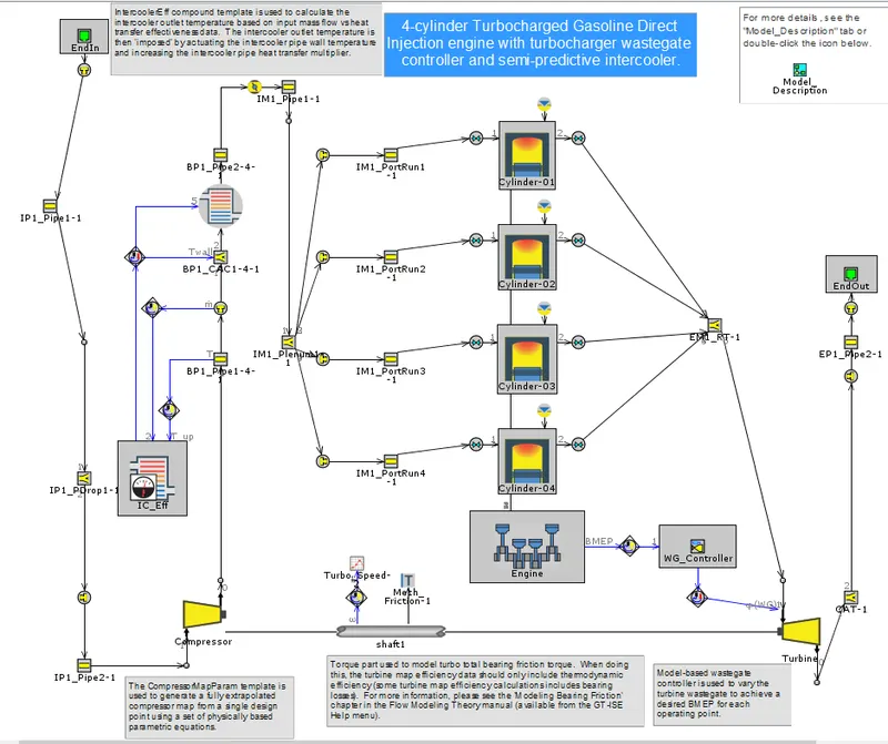
- This model is a 4-cylinder 2.0 liter turbocharged Gasoline Direct Injection (GDI) engine. The turbine wastegate is being dynamically controlled in order to target BMEP. A full-load speed sweep is being simulated, from 5000 RPM down to 1000 RPM. A semi-predictive charge air cooler is included such that the outlet temperature is predicted as a function of inlet gas temperature and mass flow rate, coolant temperature, and charge air cooler effectiveness.
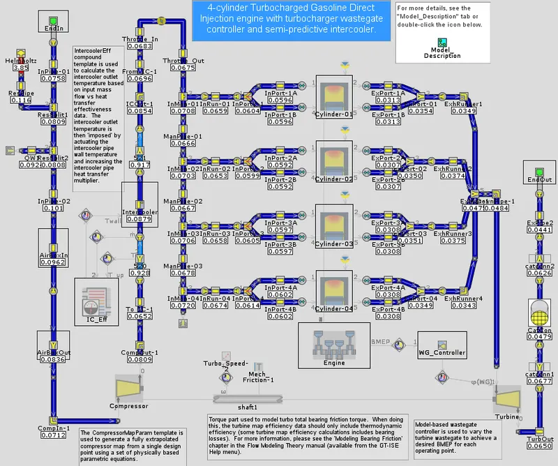
- Courant Number Map:
The Courant number is a dimensionless value representing the time a particle stays in one cell of the mesh.
C=uΔt/Δx
where C is Courant number, u is velocity magnitude, Δt is time step size and Δx is the length between mesh elements.
The lower the value, the more likely the part will limit the timestep. It is most efficient to start by simplifying the subsystem that is currently restricting the time step. For high-fidelity models, this is almost always the exhaust manifold where the highest gas velocities occur, which in turn restricts the time step.
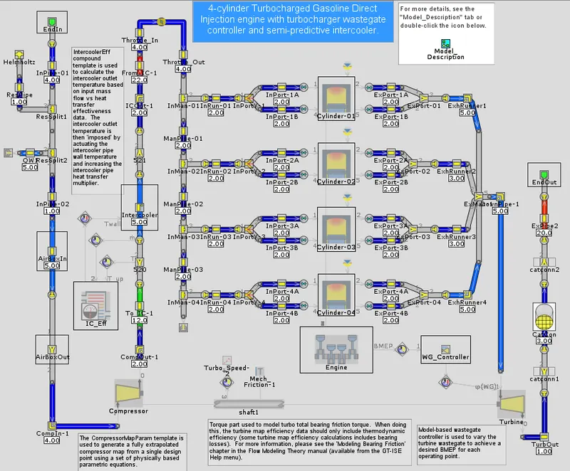
- Number of Subvolumes: Higher the subvolumes,slower the execution time.
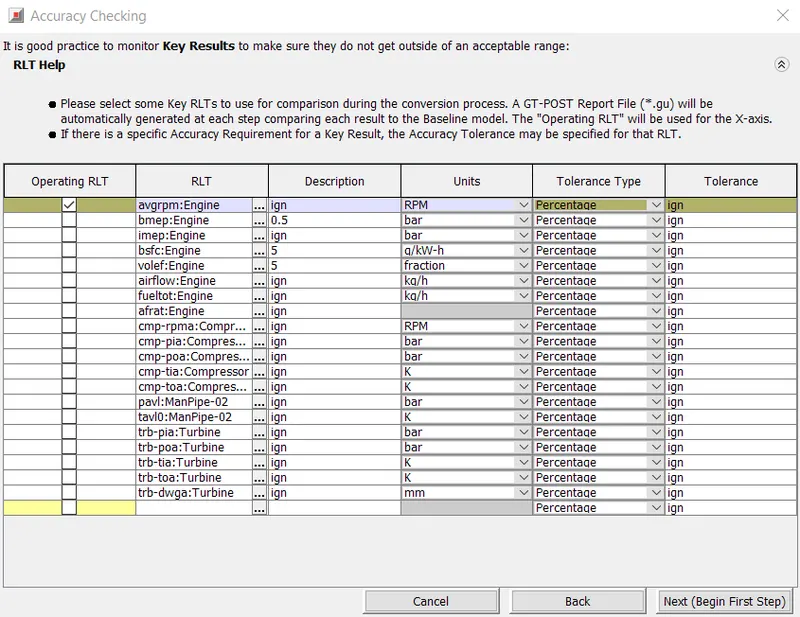
- FRM Converter: FRM Converter is a tool that will track the FRM Conversion process, organize all model
files automatically within subdirectories, and provide result comparisons of key RLTs throughout the
conversion process. - Accuracy Checking: Under FRM Converter dialog,"Accuracy Checking" is performed by selecting key RLTs to track the accuracy of the model as the conversion progresses. Optional Tolerances may be specified for which additional comparison plots will be generated,
and will be warned if a particular RLT becomes outside of a given tolerance.
Step 1-Exhaust Manifold: For Step Name, "Exhaust Manifold" is assigned and Exhaust Manifold 1 is selected from the Tagged Subsystems list. It is most efficient to start by simplifying the subsystem that is currently restricting the time step. For high-fidelity models, this is almost always the exhaust manifold where the highest gas velocities occur, which in turn restricts the time step.
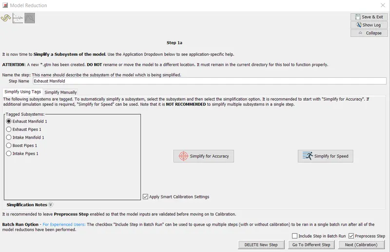
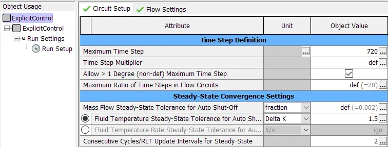
Before applying simplifications to the exhaust manifold, the Maximum Time Step limit of 1 crank angle
degree will be removed. This is a default limit that is imposed when an EngCylinder component is in the
model. If the Courant Condition allows for a larger time step (by monitoring gas velocity and subvolume
length in all flow components), removing this limit will allow the time step to increase in size.
- Set "Maximum Time Step" to 720
- Since accuracy is of higher importance than run-time, "Simplify for Accuracy" option is chosen. This combines the Exhaust Ports/Runners together, and left separate from the manifold volumes. If a real-time capable model is required then "Simplify for Speed" has to be chosen. In this case the Ports, Runners, and Manifold volumes will be combined together at once.
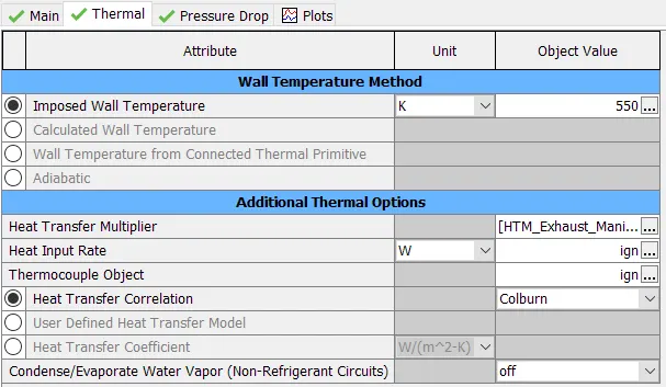
- The Discretization Length in the pipe parts will be overwritten with an automatically created parameter
called [dxe_FRM]. Its value will be set to 300mm. Port Heat Transfer dominates vs. Runner Heat Transfer,
therefore a parameter for the heat transfer multiplier called [HTM_Exhaust_Manifold_1_Step_1] will be
automatically created in all port/runner pipes Thermal tab. This parameter will be used to calibrate heat
transfer in the combined volume to assure the Turbine Inlet Temperature is maintained.
- Heat Transfer Multiplier parameter will be calibrated to match the Turbine Inlet Temperature, and so a value of 1 is simply
used as an initial guess.
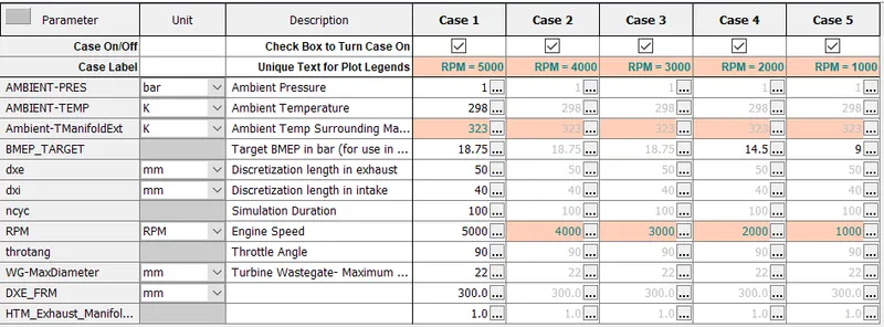
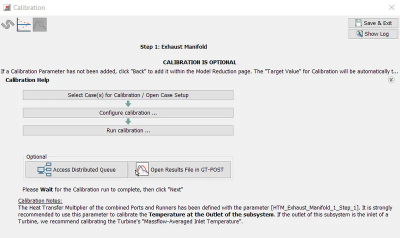
- Calibration: Number of cases to be calibrated can be chosen and configured as per the objective.
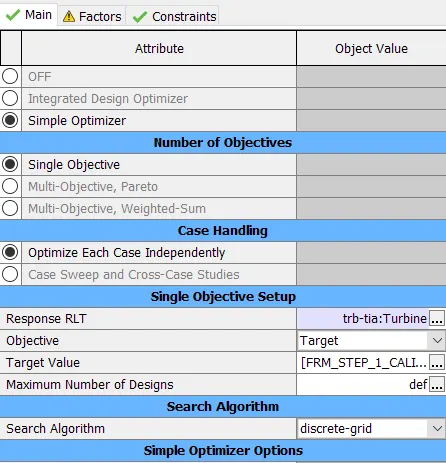
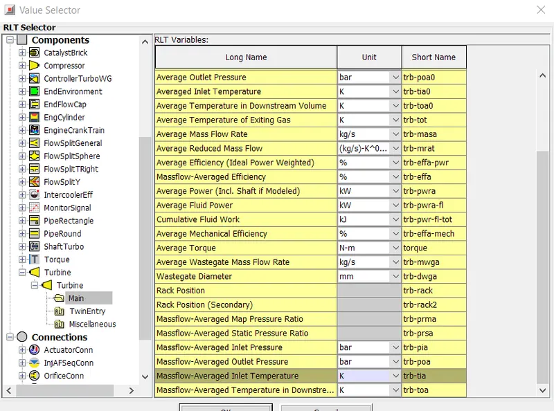
- Response is set to Massflow Averaged Inlet Turbine Temperature
- [HTM_Exhaust_Manifold_1_Step_1] parameter is set to a range of 0.95 to 2.8.
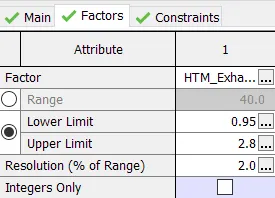
Results for Step 1:
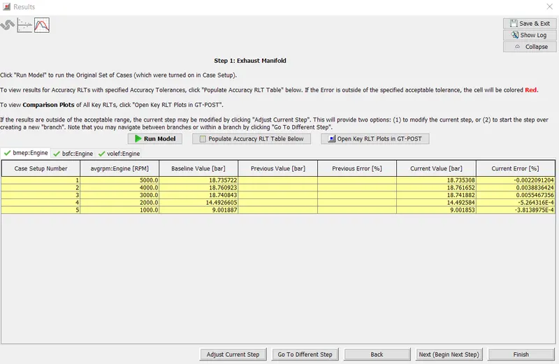
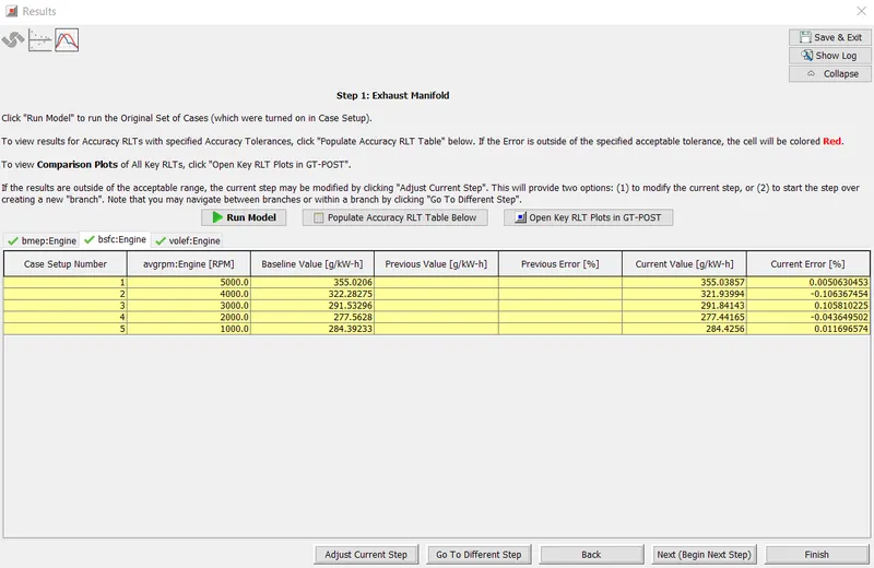
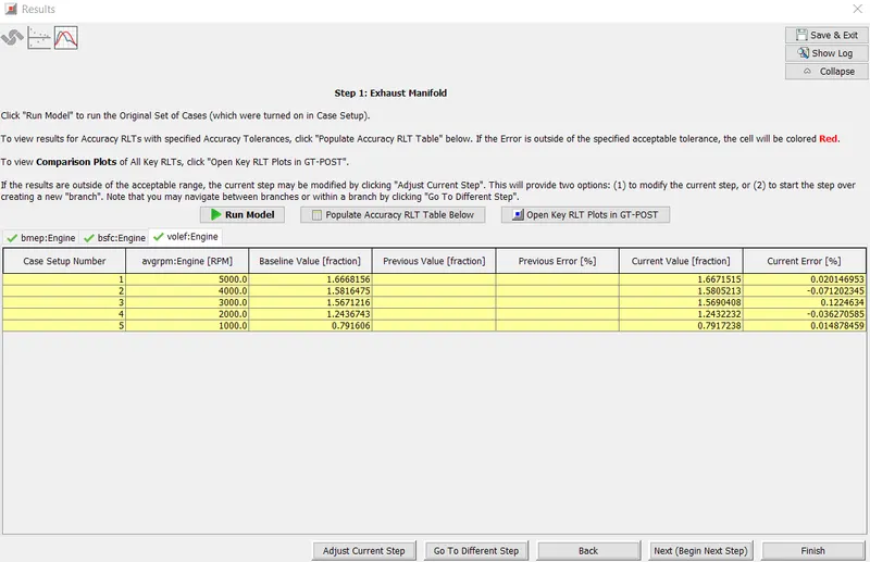
- Optimised values obtained are utilised into the defined case setups and the error between the baseline and reduced model is computed. If the obtained results are not satisfactory then it can be adjusted and rerun to obtain a satisfactory solution.
BMEP:
BSFC:
Volumetric Efficiency:
Step 2: Exhaust Pipes
- For the second step of model simplification, the exhaust pipes downstream of the turbine will be simplified. The objective is set to simplify for accuracy.
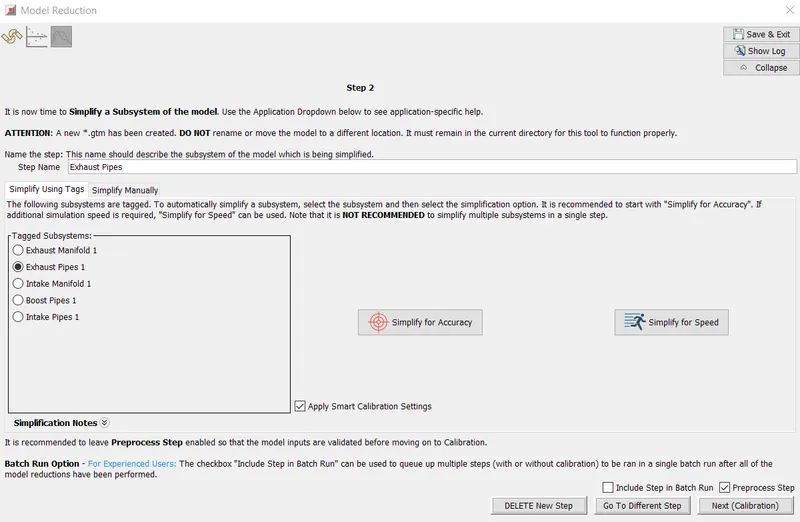
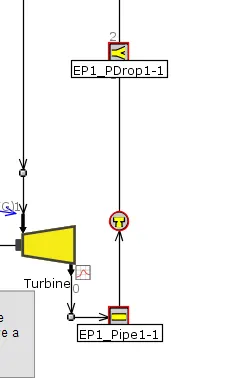
- Since the pipe at the outlet of the Turbine is rather short (70mm), this pipe will be combined with the Catalyst volumes into a single FlowSplit part. EP1_Pipe1-1 pipe along with the EP1_PDrop1-1 FlowSplit and the OrificeConn between them are selected for simplification to combine the fluid volumes.
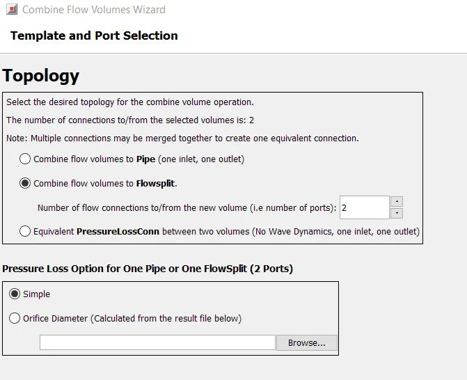
- Combined flow volumes are made as a single flowsplit and the EP1_PDrop1-1's object value is set to CAT.
- In "CAT-1" part, the condition of "Imposed Wall Temperature", "GasT" Reference Object is modified. "tav:catconn1" is replaced with "tav0:CAT-1”
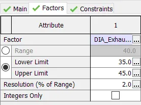
- Diameter of Exhaust pipes are set to 40mm [DIA_Exhaust_Pipes_1_Step_2] as an initial guess.
- In calibration, RLT Response is set to Turbine Massflow-Averaged Outlet Pressure (trb-poa:Turbine)
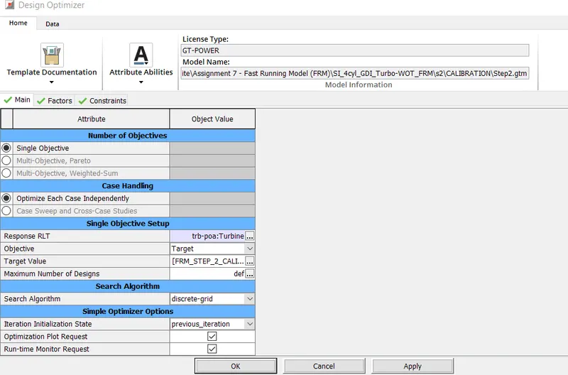
- Diameter of Exhaust pipes are set to a range of 35 to 45mm.
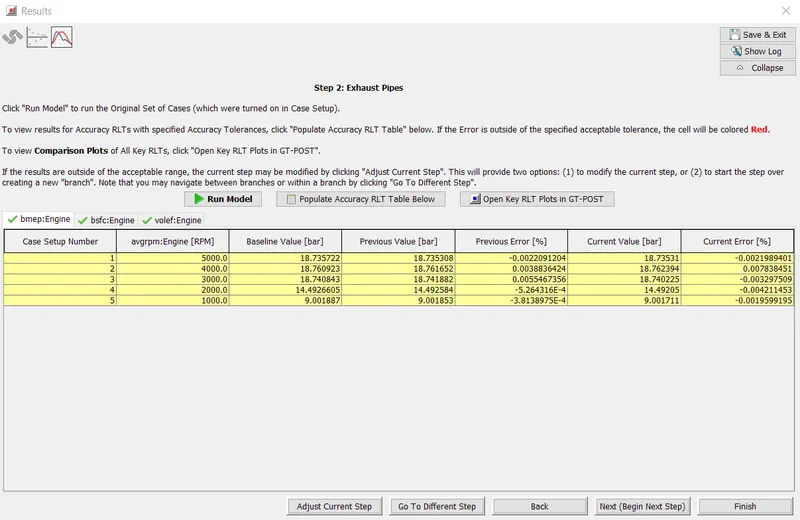
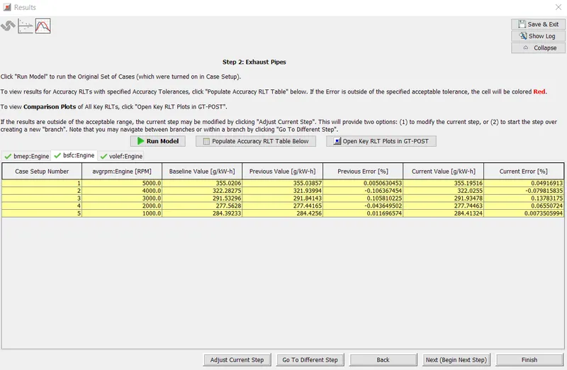
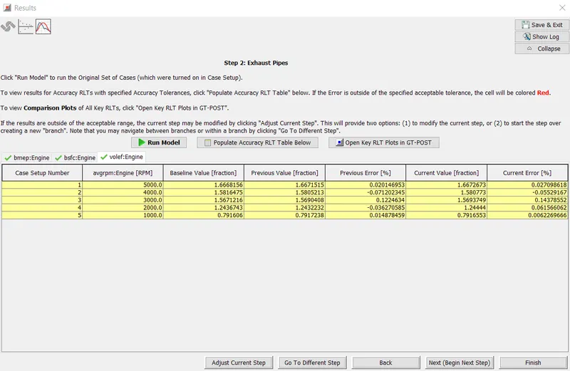
Results for Step 2:
1)BMEP
2)BSFC
3)Volumetric Efficiency
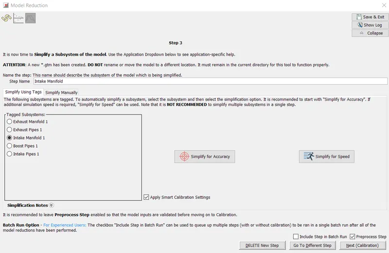
Step 3-Intake manifold:
- Minor modifications need to be made to the Characteristic Length and Expansion Diameter attribute values for the combined volume of the Intake Manifold. Again, the simplification is done for accuracy.
- In IM1_Plenum1-1 part,the Boundary Data is changed as below.
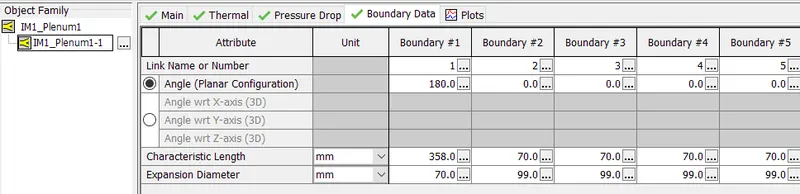
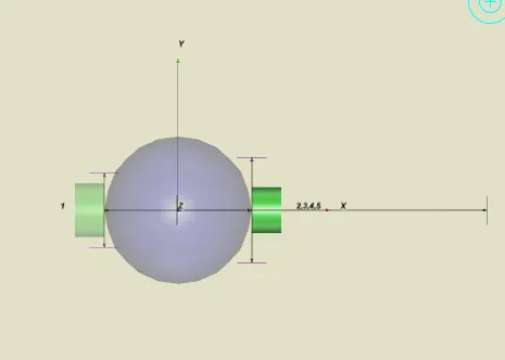
- The characteristic length is defined as the distance that the flow entering the boundary will travel before
crossing another boundary or impacting a surface. Boundary #1 represents the boundary between the
flowsplit and IM1_Pipe1-1. The fluid entering the flowsplit in this direction can travel all the way across
the plenum before impacting a surface, so the characteristic length is equal to the length of the plenum. The
other boundaries are adjacent to the runners, where backflow from the cylinder would travel across the
diameter of the plenum before impacting the plenum wall, which is why they are given a characteristic
length of 70mm. - The expansion diameter defines the maximum diameter that the flow may expand to after entering a boundary (or contract from when leaving a boundary). For Boundary #1, it is simply the diameter of the plenum because the fluid expands from IM1_Pipe1-1 into the plenum in a straight direction. The expansion diameters for the other boundaries are equal to the plenum diameter multiplied by 1.4. This is because as the fluid backflows into the plenum, it encounters a wider cross section than the plenum diameter to expand into.
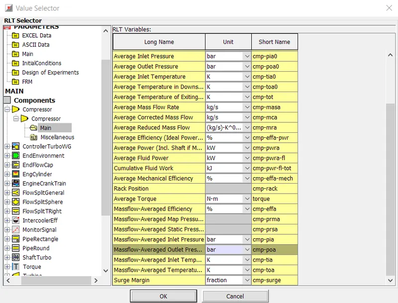
- Calibration: Response RLT is set to the Compressor Massflow-Averaged Outlet Pressure (cmp-poa:Compressor).
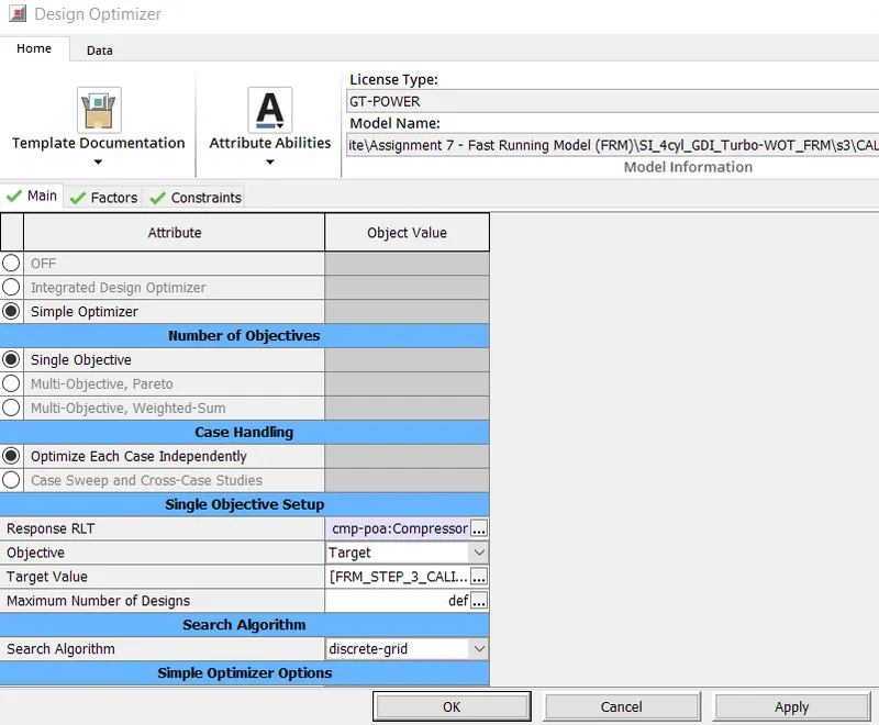
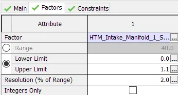
- HTM_Intake Manifold range is set to 0 to 1.1.
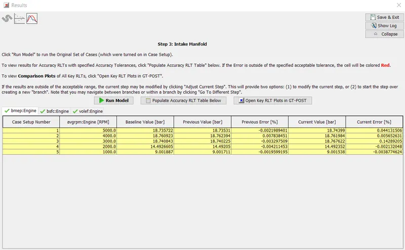
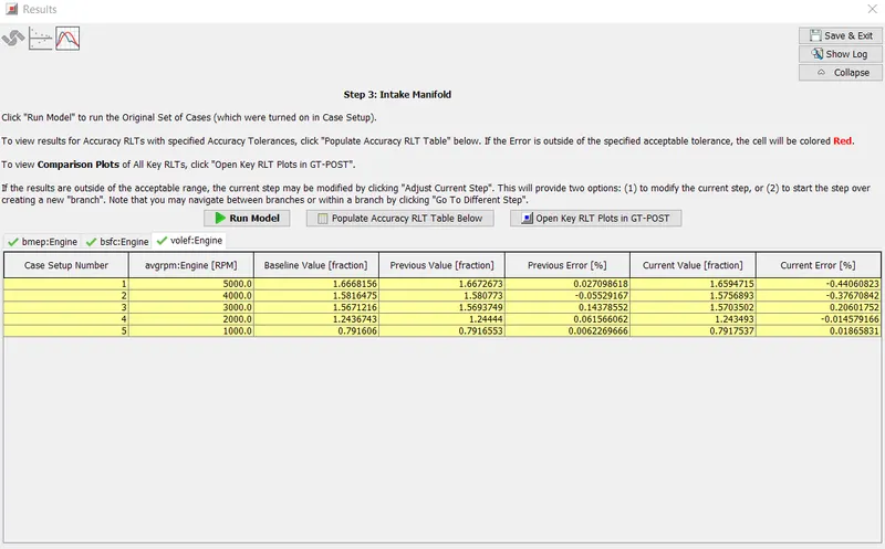
Results for Step 3:
1) BMEP
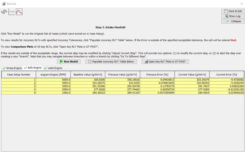
2)BSFC
3)Volumetric Efficiency
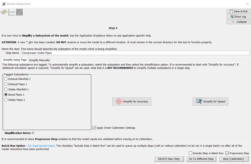
Step 4-Boost pipes-Compressor Outlet Pipes:
- In step 4, the intercooler core (previously a bundle of pipes) has been replaced with a FlowSplit and "HeatExchangerConn" part. The "BP1_CAC1-2 HeatExchangerConn" part will be used to assure the intercooler outlet temperature is maintained.
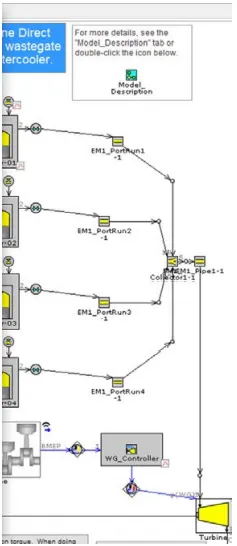
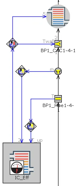
- Control links are connected for sensing Upstream Temperature from "BP1_Pipe1-4" Pipe and Upstream Mass Flow Rate from the "6” OrificeConn upstream of the "BP1_CAC1-4-1" Flowsplit, and sending the actuator output to both "BP1_CAC1-4-1" Flowsplit (actuating Wall Temperature) and to the HeatExchangerConn (actuating Imposed Fluid Temperature) as shown below.
- In Case Setup,[DIA_Boost_Pipes_1_Step_4] is set to 35 mm as an initial guess.
- Calibration: Response RLT is set again as step 3 to Compressor Massflow-Averaged Outlet Pressure (cmp-poa:Compressor). Since the wastegate controller is maintaining engine BMEP, engine air flow is also effectively maintained since the Air-to-Fuel ratio is fixed. Therefore, as the effective diameter of the Intercooler changes, the resulting compressor outlet pressure will change so that engine air flow is maintained (via the wastegate controller). Therefore, the Intercooler Diameter will be adjusted in order to maintain compressor outlet pressure.
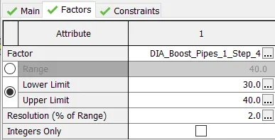
- [DIA_Boost_Pipes_1_Step_4] is set between the range of 30 to 40mm.
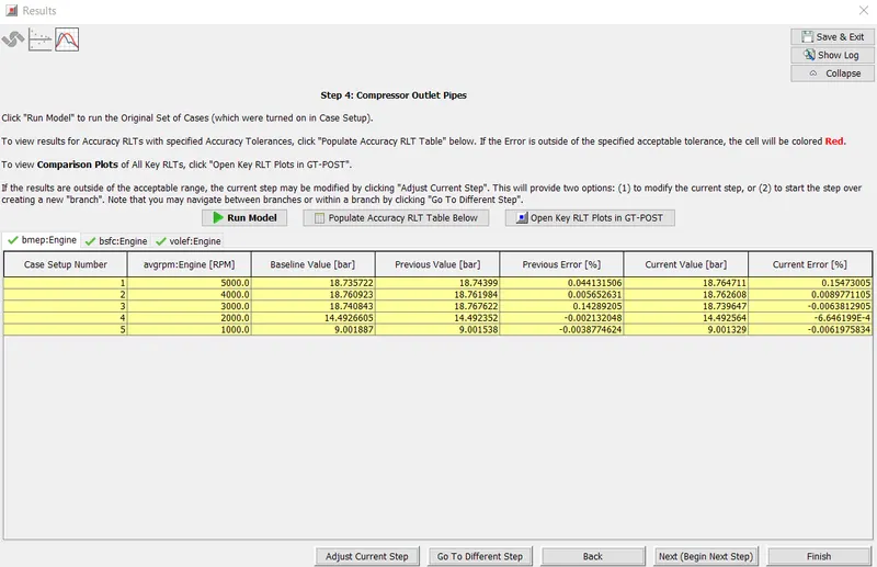
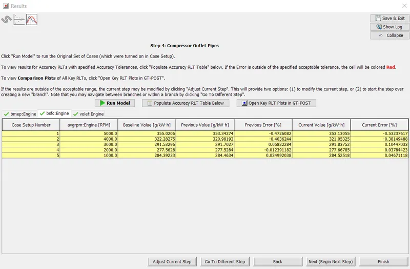
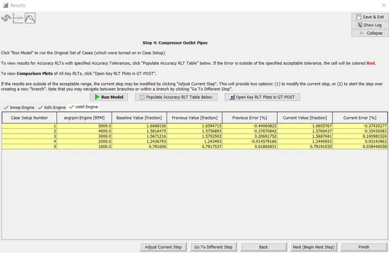
Results for Step 4:
1)BMEP:
2)BSFC:
3)Volumetric efficiency:
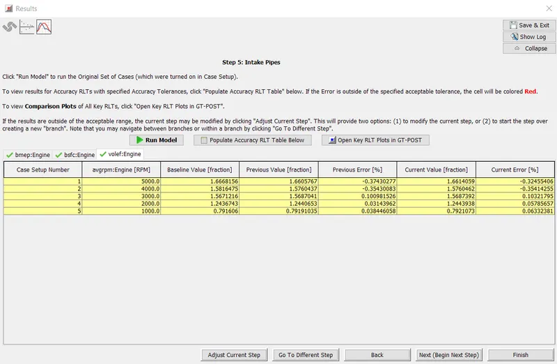
Step 5: Intake pipes
- In this step, all the inlet pipes are simplified with accuracy.
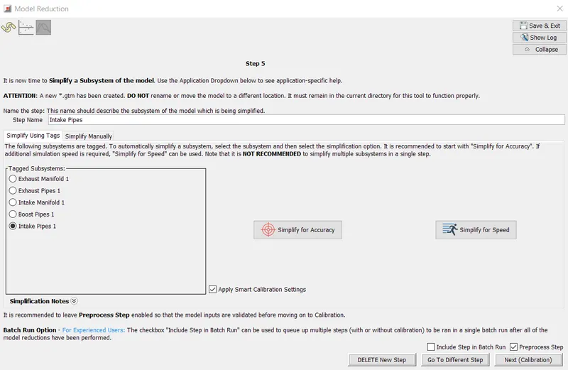
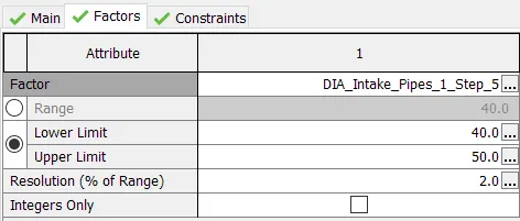
- In case setup, diameter [DIA_Intake_Pipes_1_Step_5] is set to 45mm as an initial guess.
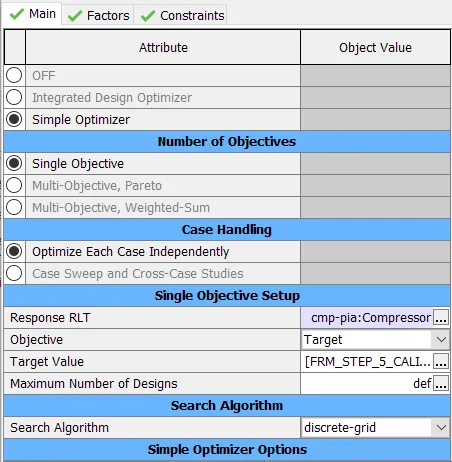
- The model is calibrated with Compressor Massflow-Averaged Inlet Pressure (cmp-pia:Compressor) as RLT with a range of 40 to 50mm.
Results for Step 5:
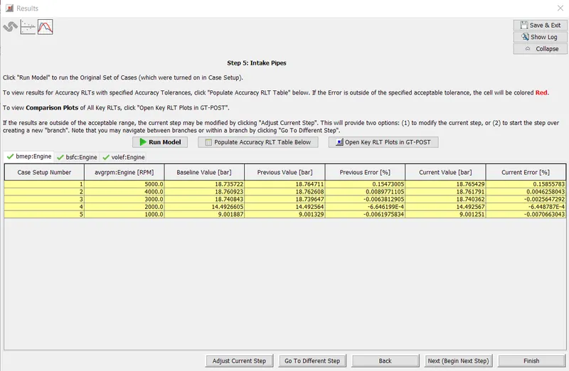
1)BMEP
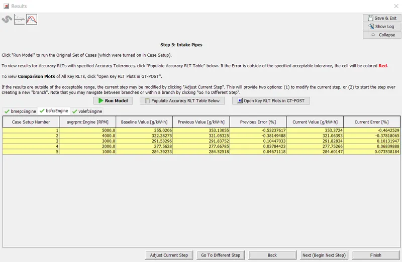
2)BSFC
3)Volumetric Efficiency
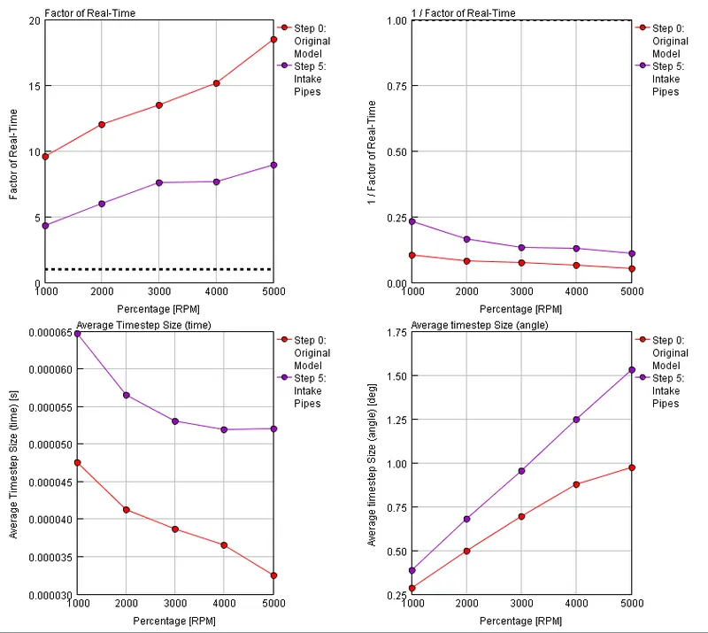
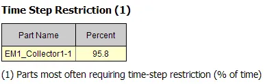
From the above plots it is clear that the FRM model is superior in terms of run-time, thus making it most efficient to run in real time. However, Exhaust Manifold requires restriction almost 96% of the time. Therefore, as a next step, Exhaust manifold is simplified for speed.
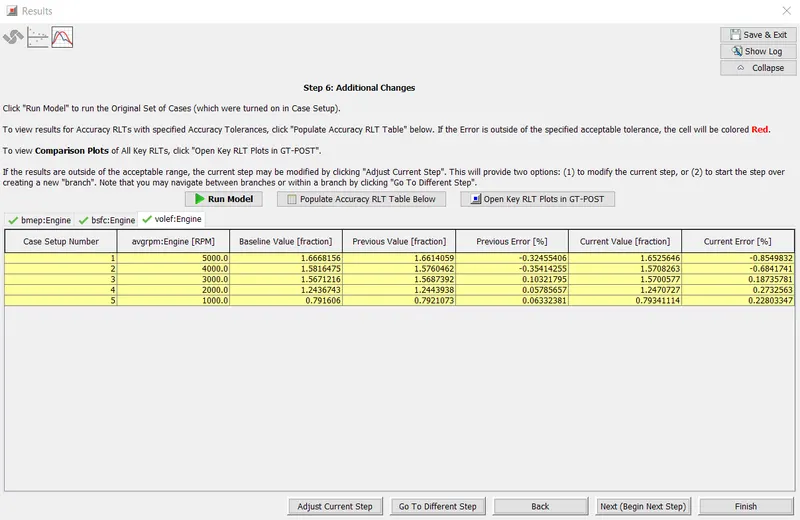
Step 6-Additional Changes:
- As observed from step 5, that the exhaust manifold requires time step restriction 96% of the time. Hence, Exhaust Manifold is simplified for speed.
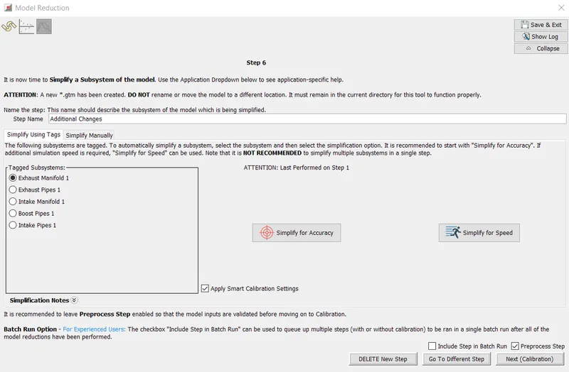
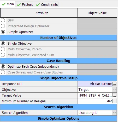
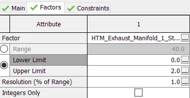
- The model is calibrated with Turbine Massflow-Averaged Inlet Temperature (trb-tia:Turbine) as RLT and HTM_Exhaust is set to a range of 0 and 2.
Results for Step 6:
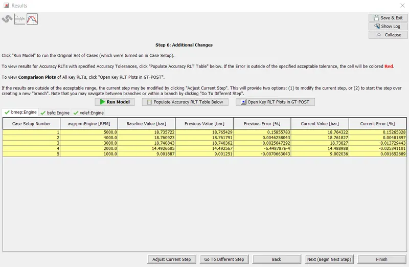
1)BMEP
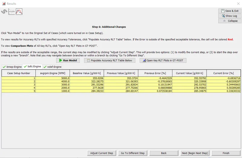
2)BSFC
3)Volumetric Efficiency
Step 7-Cylinder Slaving:
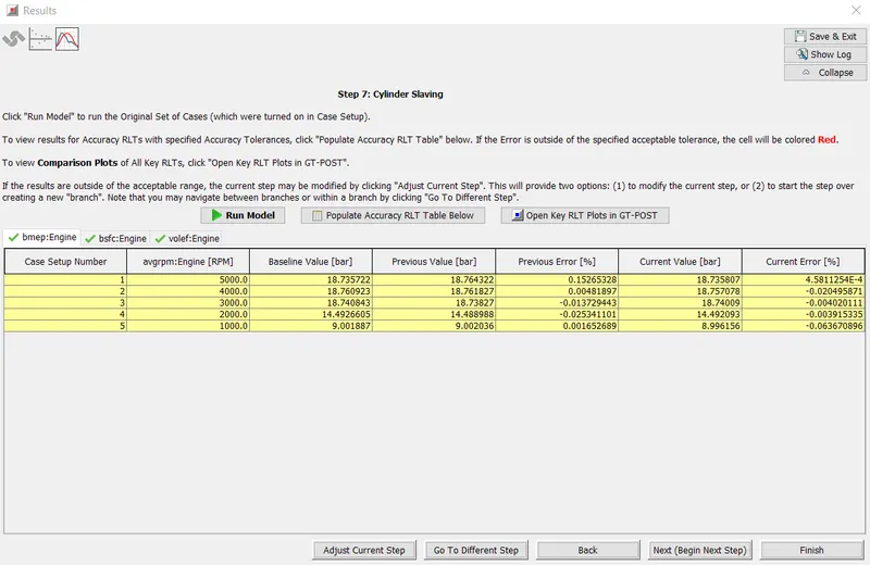
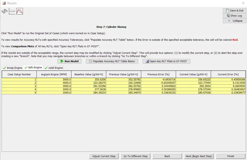
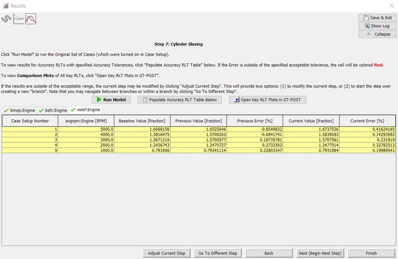
- The final simplification to the model will utilize the Cylinder Slaving capability of the EngCylinder component.
Results for Step 7:
1)BMEP
2)BSFC
3)Volumetric Efficiency
Final Model:
Inference:
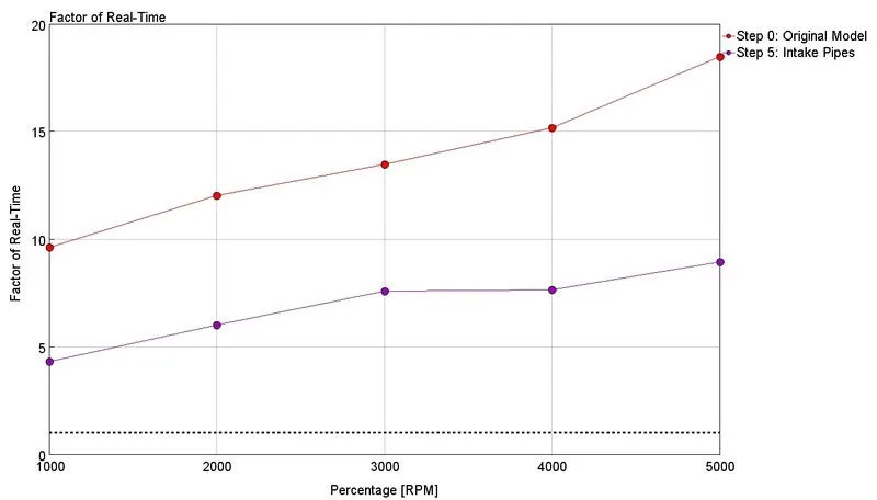
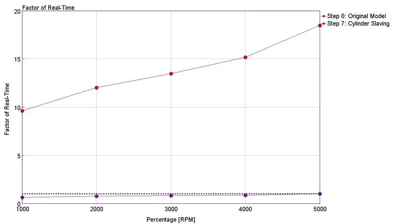
From the above plots, Difference in factor of real time between Step 5 and Step 7 is clearly significant. This is due to the fact that the exhaust manifold undergoes higher velocity thereby limiting the time step. Simplifying it for Speed has enhanced the speed of the model.
FRM Builder:
Objectives:
- Bore 102 mm stroke 115 mm CR 17
- No of cylinder 6
- CI engine
- Twin Scroll Turbine
- GT Controller
Engine Type:
Engine Geometry:
Turbocharger Type:
No. of Cylinders:
Controller:
Final Model:
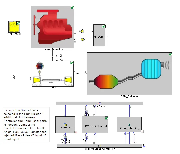
Result:
Case Setup:


Simulation Run time:



Inference:
- Higher the RPM, longer the runtime.