Week-4 : Basic Calibration of Single cylinder CI-Engine
Basic Calibration of Single cylinder CI-Engine
Objectives:
1.Compare SI vs CI and list down differences
2.Change MFB 50 and observe its impact on performance
Single Cylinder CI Engine Model:
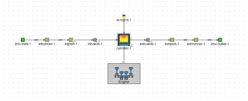
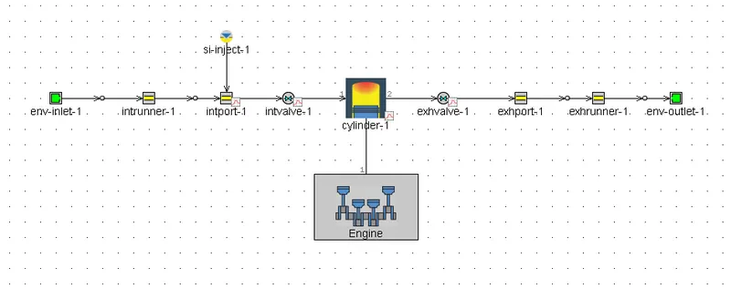
Fig. CI Engine (Left) and SI Engine (Right)
Schematically, the major difference between the SI and CI engine is the mixing of fuel. In SI engine model (si inject 1 connected to intport-1), the fuel is premixed with air and passed into the combustion chamber whereas in CI engine the fuel is injected directly into the combustion chamber (di inject 1 connected to cylinder-1) while air is injected separately leading to AF mixing to happen right inside the combustion chamber.
SI vs CI Engine at 1800 RPM:
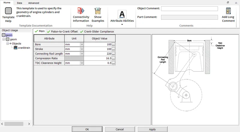
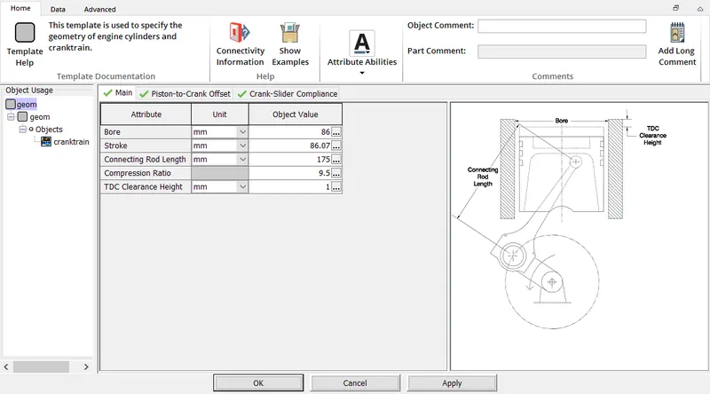
Fig. CI Engine (Left) and SI Engine (Right)
The Combustion chamber geometry varies between SI and CI engine. CI engine has higher compression ratio in order to achieve its self ignition temperature.
Results:
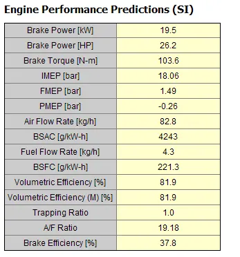
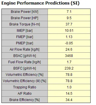
Fig. CI Engine (Left) and SI Engine (Right)
Inferences:
- Power and Torque: Brake Power and Brake Torque is on the higher side in CI Engine. This is due to the fact that the compression ratio is high and calorific value of Diesel.
- BMEP: Higher Brake Power and Torque also means that the BMEP is on the higher side in CI Engine.
- A/F Ratio: Air Flow rate is higher in CI than SI Engine. This is obvious as the A/F ratio is always around 20 in CI Engine (Fuel Lean Mixture) against SI Engine (Stochiometric Mixture) which is below 15.
- BSFC: BSFC is lesser in CI Engine when compared to SI Engine. This means that the fuel consumption is less in case of CI Engine making it fuel efficient.
Influence of MFB 50:
- Mass fraction burned (MFB) in each individual engine cycle is a normalized quantity, describing the process of chemical energy release as a function of crank angle. MFB is used to evaluate ignition delay and combustion duration by dividing the amount of accumulated fuel or accumulated heat during the combustion period by the total fuel or total heat release.
- MFB50 denotes the position in terms of crank angle where 50% of fuel mass burned over an engine cycle is reached.
- Analytical functions approximating the burn rate in internal combustion engines are useful and cost-effective tools for engine cycle simulations. Most functions proposed to date are based on the law of normal distribution of a continuous random variable. The best
known of these is the Wiebe function, which is used to predict the burn fraction and burn rate in internal combustion engines operating with different combustion systems and fuels.
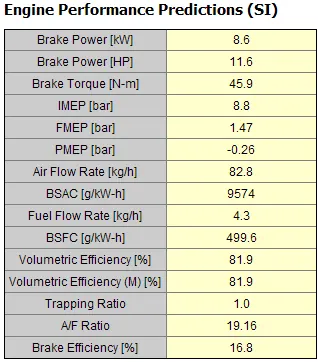
Fig. MFB100 CI Engine (Left) and MFB50 CI Engine(Right)
Inference:
At MFB50, Brake Power and Toque are almost halved than at 100% as only small amount of fuel is burnt. On the other hand,BSFC doubles to produce required RPM at MFB50 which reduces the fuel efficiency.
References:
[1] Internal Combustion Engines Fundamentals by John B Heywood
[2] Combustion control using a Model-based MFB50 estimation methodology, Fabrizio Ponti*, Vittorio Ravaglioli**, Davide Moro***, Gabriele Serra, 6th IFAC Symposium Advances in Automotive Control, 2010