Week 3 Challenge : CFD meshing on Turbocharger
Aim - To Perform Surface Meshing And Volumetric Meshing for the given Geometry
Objective - To Perform Geometrical Errors CleanUp, Surface Meshing & Volume Meshing by setting up different target length as per PIDs given below
- Blade stage-1 = 1 mm
- Blade stage-2 = 1 mm
- Impeller = 2 mm
- Shaft rotor = 1 mm
- Turbo casing = 5 mm
- Compressor casing = 5 mm
- Inlet casing cover = 5 mm
Introduction -
Turbocharger
A turbocharger is a turbine-driven force induction device that increases the efficiency and power output of internal combustion engines by forcing extra compressed air into the combustion chamber. This hot air induction seems to work because the compressor can force more air and proportionately more fuel into the combustion chamber than normal atmospheric pressure.
- Extra oomph is provided without increasing the engine capacity.
- Make the engine run faster without an increase of fuel burning rate.
- Make use of carbon II oxide (exhaust gas) instead of causing pollution.
Geometrical Cleanup Of Turbocharger
After importing the raw geometry, the first thing we should check are the units.
We can perform this step under Tools -> Settings -> Resolution/Tolerance/Units
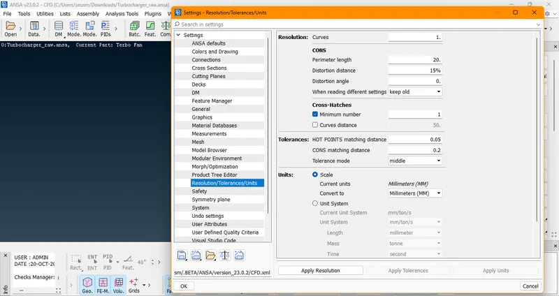
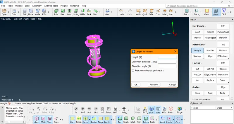
Then we should check for resolution (perimeter). If the raw geometry has distortion, it can be fixed by changing its perimeter.
We can perform this operation under Mesh -> Length -> Perimeter ->Select the whole geometry -> Length Parameters.
Then we should check for the orientation of the geometry.
Here, we need to check whether the analysis is internal flow analysis or external flow analysis and then we can decide which side should be grey in color and which should be yellow in color
While using ANSA, Grey Color represent the positive side and the side where the fluid is interacting and similarly Yellow Color represent the negative side.
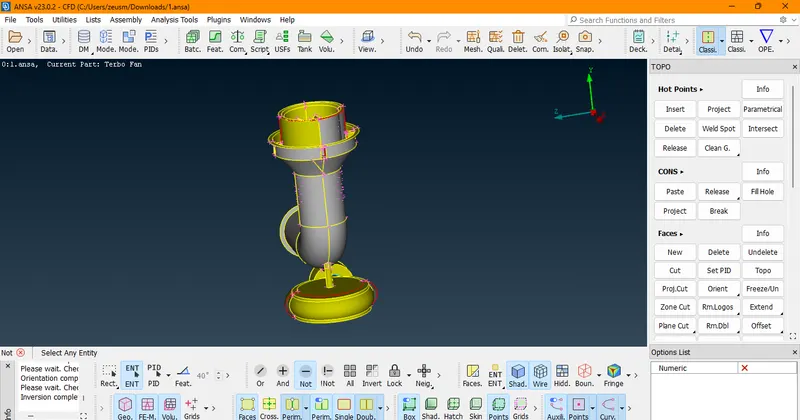
As we are performing internal flow analysis, the thickness of the geometry becomes redundant, so to remove those thicknesses, we are performing COONS release operations, which will project those thicknesses as free surfaces.
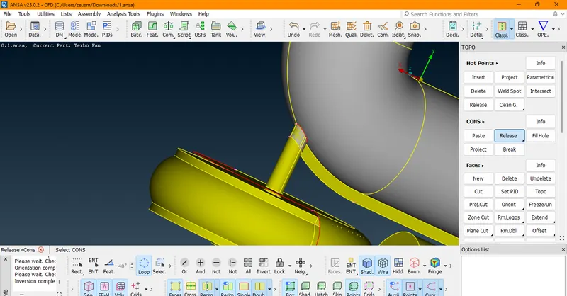
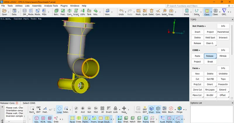
After fixing all the geometrical errors, we finally got our water-tight geometry.
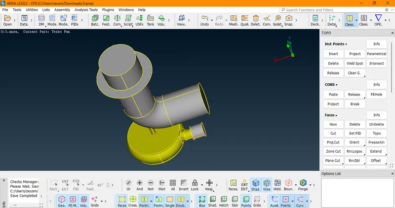
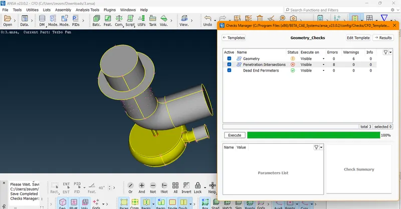
Now we need to check the geometry and intersection errors present in the geometry.
Checks -> Checks Manager -> Geometry Checks
Now, we can see there are triple coons present on the shaft
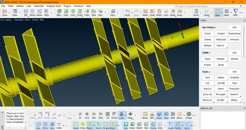
Here, we need to decide the future of triple coons we need to keep it or not...If we want to define it as a multiple volume triple coons, similarly if we want to define it as a single volume triple coons should be eliminated.
After fixing all the geometrical and intersection errors, we finally achieved our clean geometry.
Now after geometrical cleanup we need to assign PIDs to different components of the given geometry,so here is
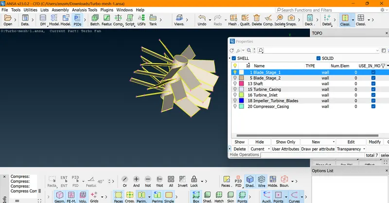
Blade Stage-1
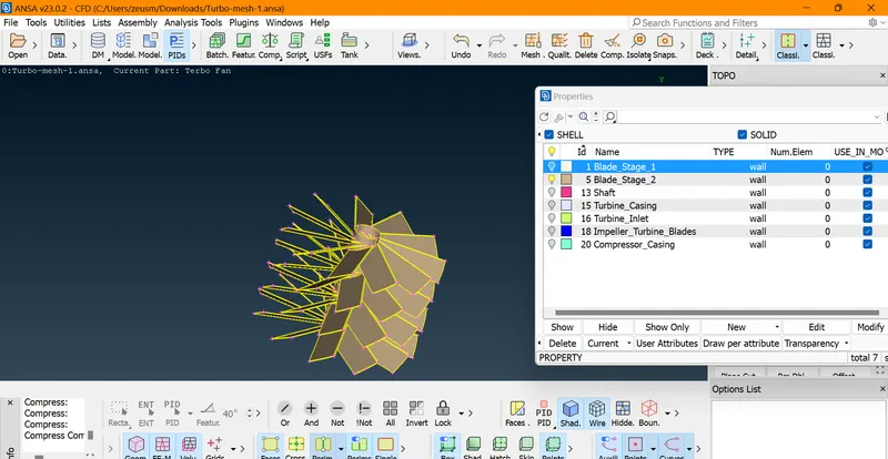
Blade Stage-2
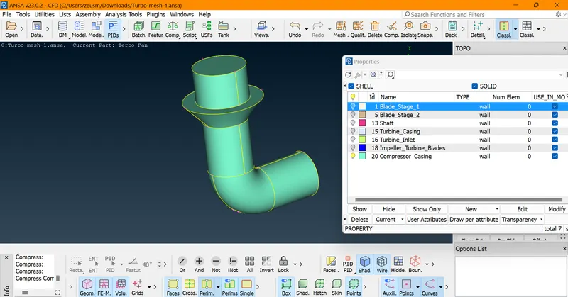
Compressor Casing
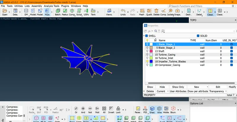
Impeller
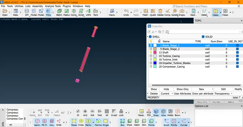
Shaft
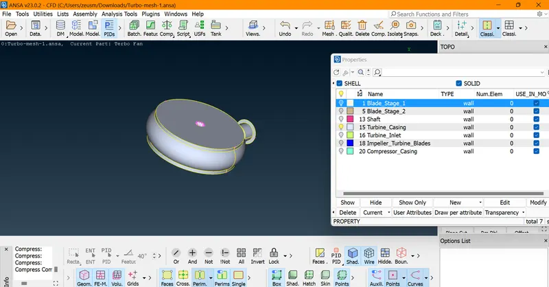
Turbine Casing
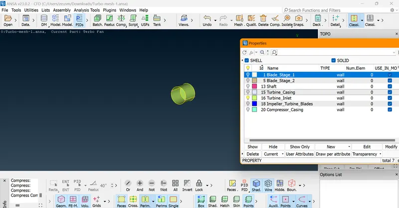
Turbine Inlet
Now we need to move to the Mesh Deck and start our Meshing Process.
Here,First of all we need to perform Surface Meshing Operation.
Surface Meshing - A surface mesh consists of a set of polygonal faces, often triangles, that, taken together, form a surface covering of the object. The advantage of a surface mesh is that it is fast to generate and works very well for visualization. It uses two-dimensional elements, typically triangles or quads, to approximate the outer surface of a 3D body. Surface meshes are used in manufacturing or rendering applications and CAE simulation.
Batch Mesh Manager -> New -> Meshing Scienario -> Edit -> Contents -> Select all the available contents
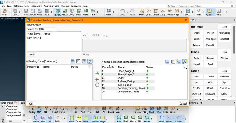
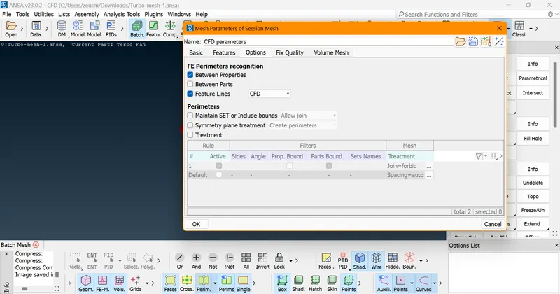
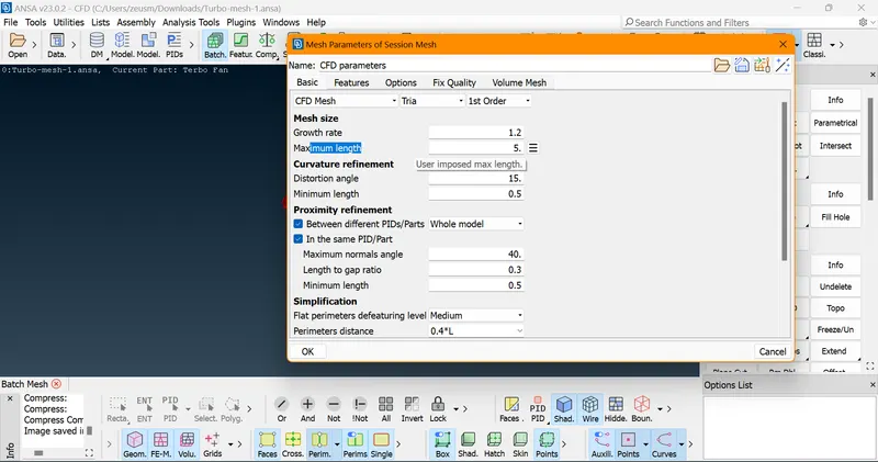
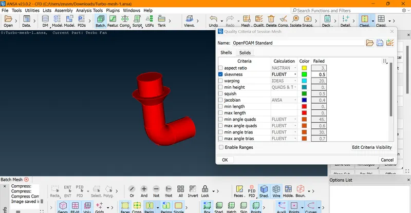
We have configured our Batch Mesh Manager Meshing Configuration and Quality Criteria and now we can proceed further.
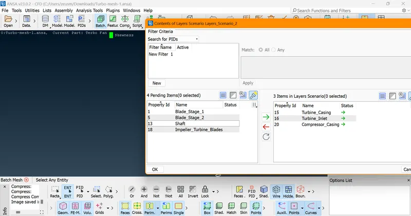
After that, we need to define Layers Scienario
Batch Mesh Manager -> New -> Layers Scienario -> Edit -> Contents
We have assigned layers scenario to capture the boundary layer near the wall area, i.e., casing and inlet.
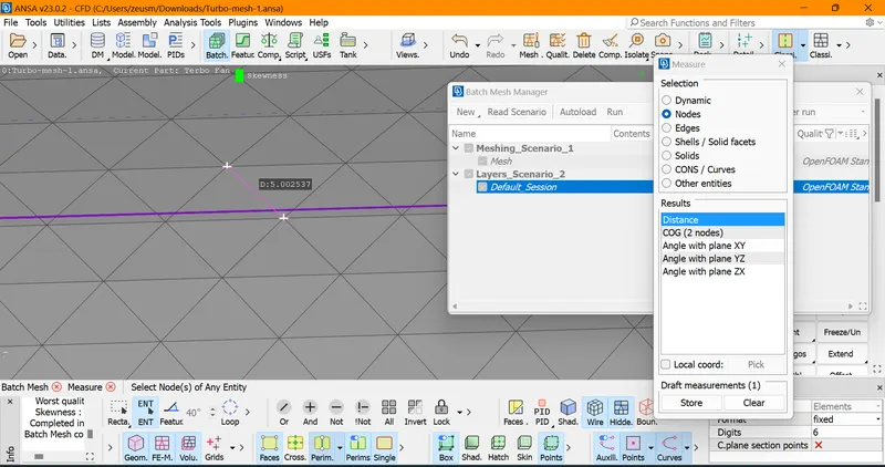
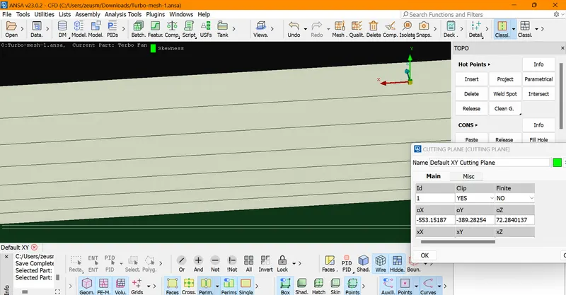
We can observe our seven boundary layers in Cut Section View Plane.
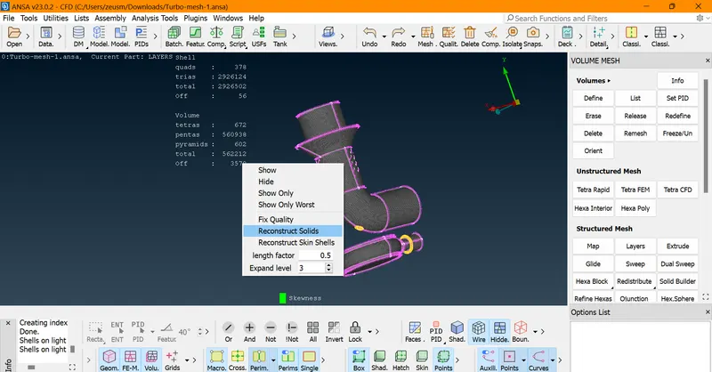
We can observe here that there are lots of off elements which needs to be fix..
We can use Reconstruct Solids which would help us to imrove such off-elements..After hitting it a few times,it helped us decrease our off-elements significantly.
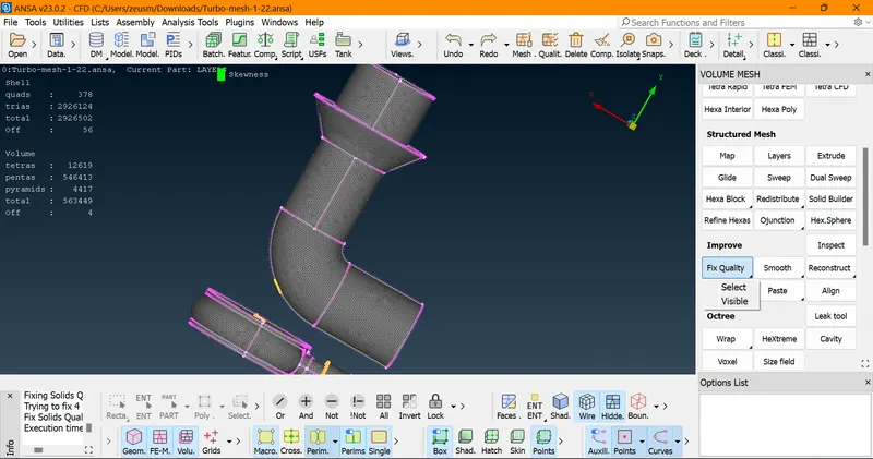
Now, we tried to fix off-elements using Improve -> Fix Quality -> Visible which helped us eliminate our off elements successfully.
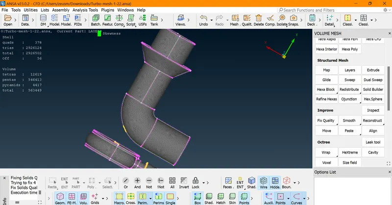
Now we can move to Volumetric Meshing
While trying to generate volumetric meshing, there was an intersection error that popped up.Which got fixed by erasing and re-generating CFD Mesh in that specific region and some off-elements was fixed by re-shape the geometry in that specific region.
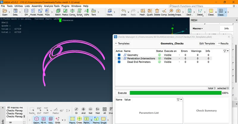
Now after fixing few Unmeshed Elements Error..Finally fully Meshed Geometry is achieved.
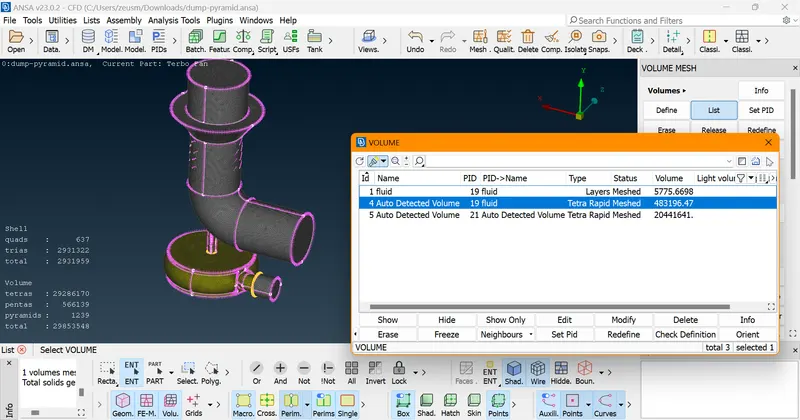
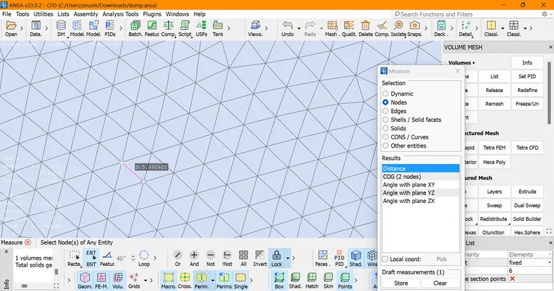
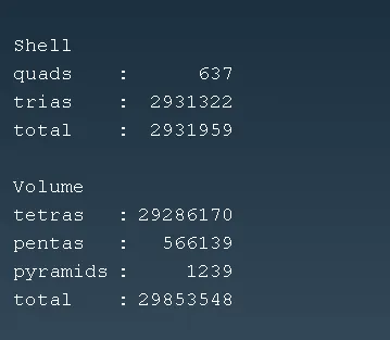
Results
File Link - https://drive.google.com/file/d/16Pu6JMv_SyVM4O8mUO3R33lXgoy3vzOw/view?usp=share_link