Week 6 - CHT Analysis on a Graphics card
Aim : To perform a steady-state conjugate heat transfer analysis on graphics card
Objectives : To perform a steady-state conjugate heat transfer analysis on graphics card and
- Run the simulation by varying the velocity from 1m/sec to 5m/sec for at least 3 velocities and discuss the results.
- Find out the maximum temperature and heat transfer coefficient attained by the processor.
- Prove that the simulation has achieved convergence with appropriate images and plots.
- Identify potential hotspots on the model.
Theory :
- CHT analysis refers to "conjugate heat transfer analysis," and it allows us to perform simulations of heat transfer between solid and fluid domains with exchange of thermal energy at the interfaces between them. This type of heat transfer analysis includes both conduction( between solids) and convection (between fluids) heat transfer, and it is also applicable in the case of both natural and forced convection processes.
- It is used in case of electronics cooling, heat exchangers and heavy industrial machinery etc.
- It also provides the temperature predictions and hotspot regions at the solid-fluid interface and we can also calculate the heat transfer coefficient value
Geometry Preparation :
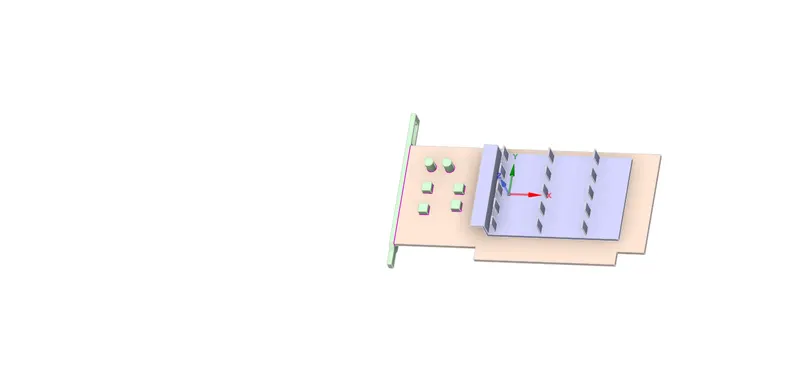
Importing our Geometry in Spaceclaim.
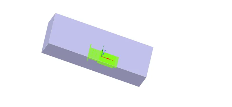
Graphics Card within Enclosure
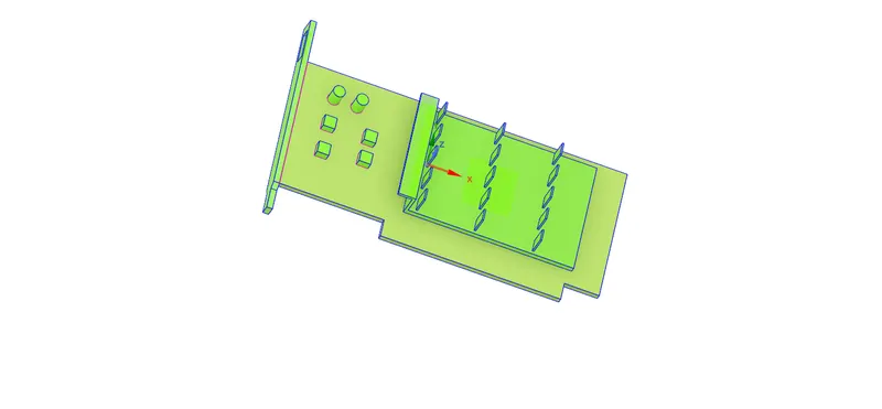
Graphics Card
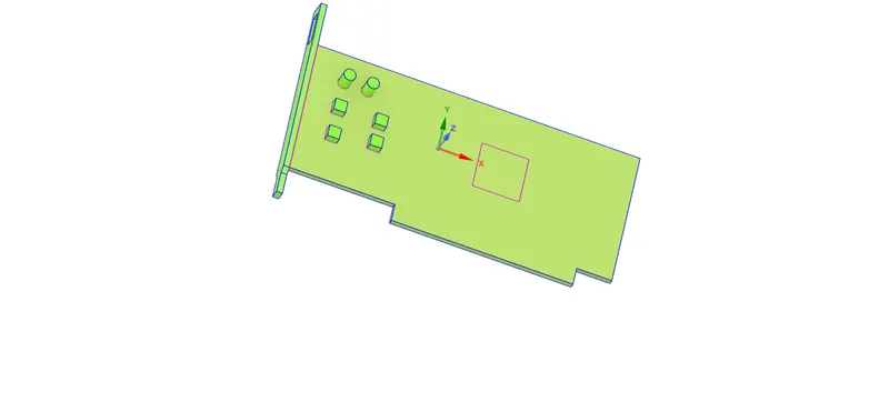
Base

Processor
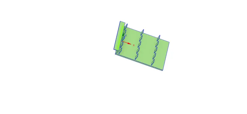
Fins Base
Sharing Topology
For Conformal Meshing, we need to perform Share Toplogy on our geometry
Workbench -> Share -> Confirm Selection
Meshing The Geometry
Named Selections
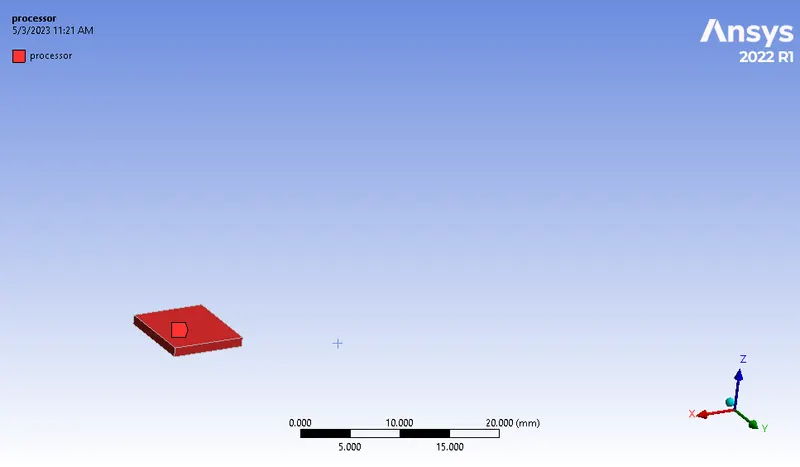
Processor
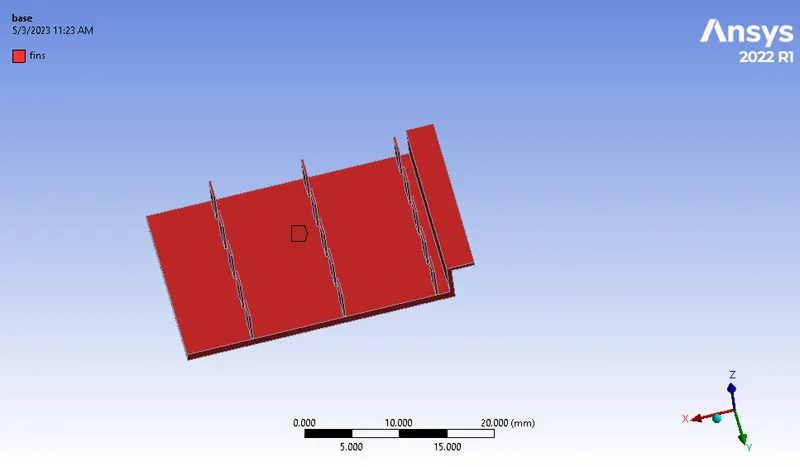
Fins
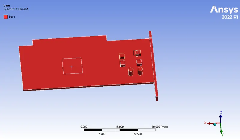
Base
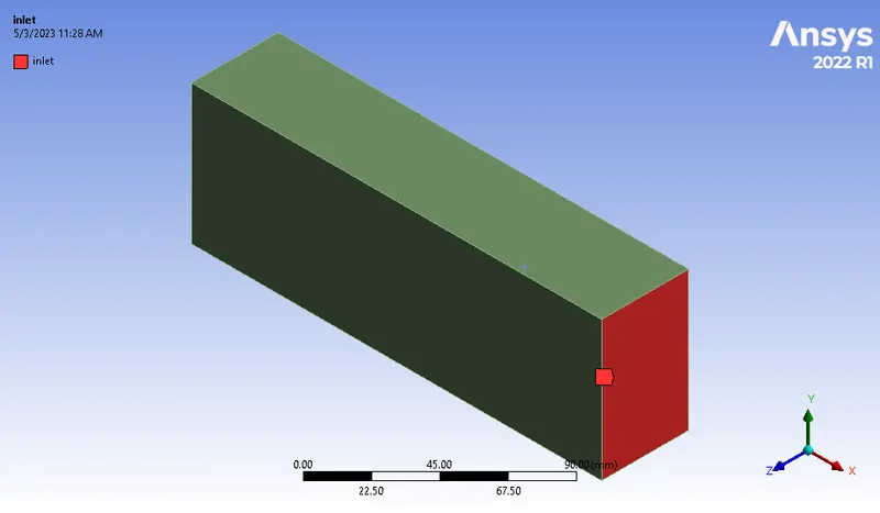
Inlet
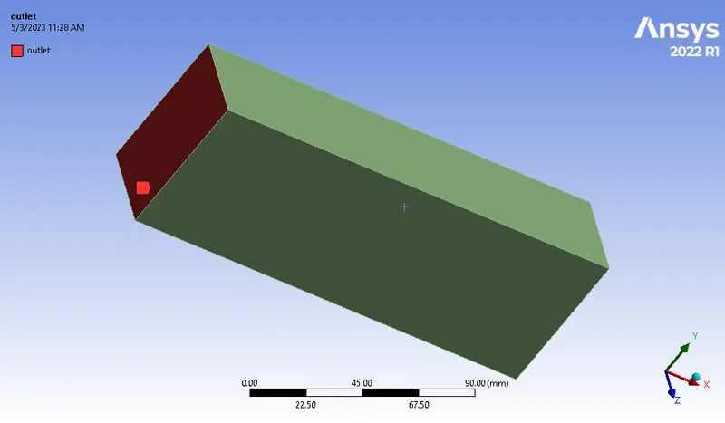
Outlet
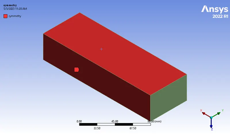
Symmetry
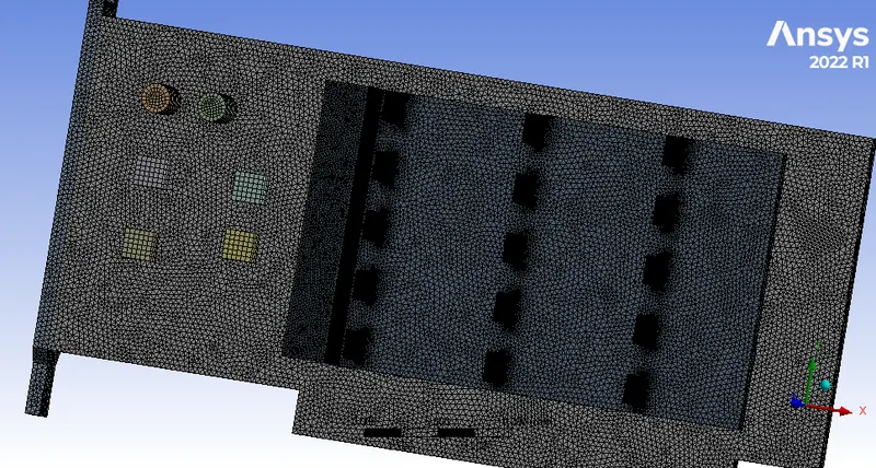
Meshed Geometry
Enclosure Meshing
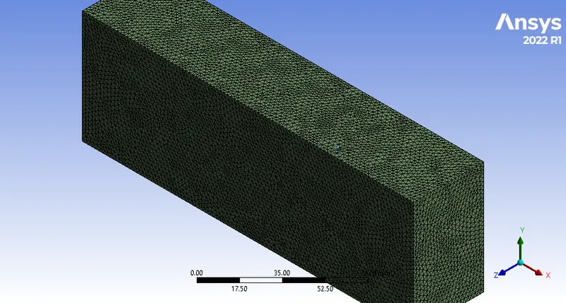
Graphics Card Meshing
Refined Mesh has been provided on our Graphics Card Region as it is our area of interest.
Mesh Metrics
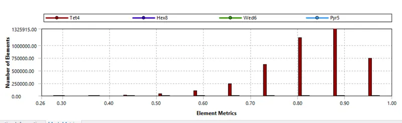
Mesh Counts

Setup
- Solver Type : Pressure Based
- Solver Time : Steady State
- Turbulence Model : K-Omega-SST
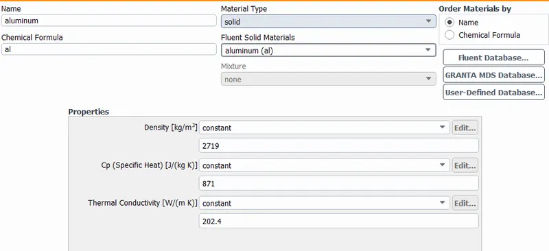
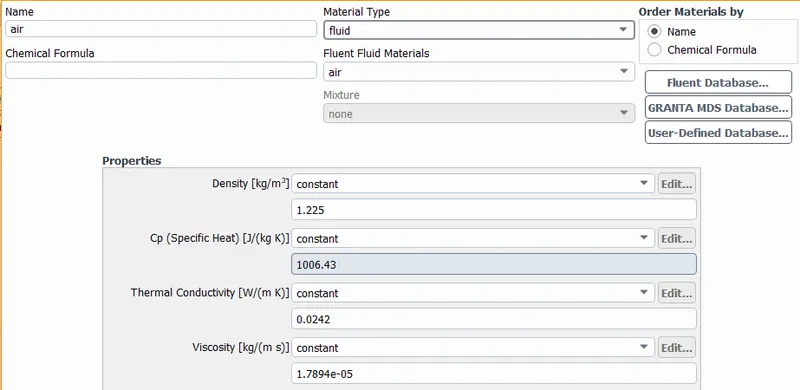
- Materials Used
- Base(PCB) -> FR4
- Fins -> Aluminium
- Processor -> Silicon
- Encloser -> Air
- FR-4 is the most commonly used material in printed circuit board (PCB) construction and is made up of flame-retardant epoxy-resin and glass-fabric composites.
- Silicon is a widely used semiconductor material. Processors are manufactured using silicon primarily.
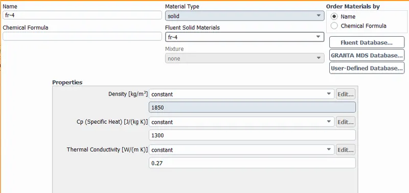
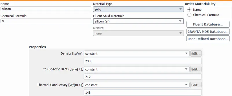
Cell Zone Conditions
Base -> Solid -> FR-4
Fins -> Solid -> Aluminium
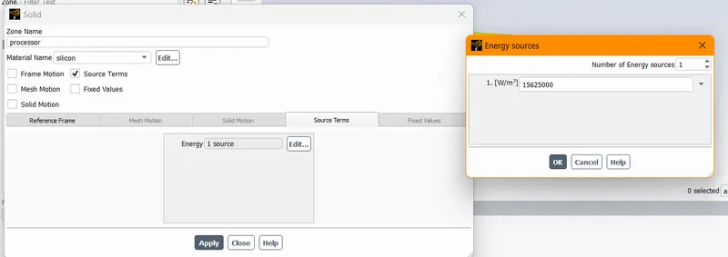
Processor -> Silicon -> Source Terms
Calculations
- Power of our Graphics Card = 1 Watt
- Volume of our Graphics Card = 8x8x1 mm^3 = 64 mm^3 = 64 e-9 m^3
- Heat Generated(Watt/m^3) = (1)/(64 e-9) Watt/mm^3 = 15625000 Watt/m^3
- Length = 8 mm = 8 e -3 m
- Area = 8 x 4 mm^2 = 32 mm^2 = 32 mm x mm = 32 x (0.001 m) x (0.001 m) = 3.2 e -5 m^2
Post Processing Results
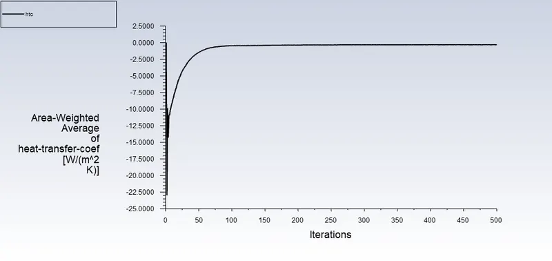
For Velocity = 1 m/s with refined mesh
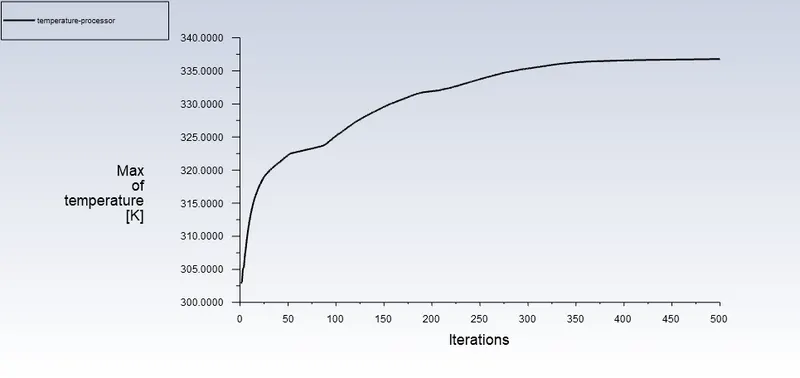
- Maximum Temperature attained by the processor
- Heat Transfer Coefficient attained by the processor
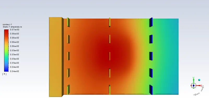
- Potential Hotspot
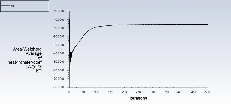
For Velocity 3 m/s with refined mesh
- Heat Transfer Coefficient attained by the processor
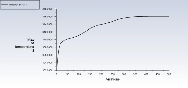
- Maximum Temperature attained by the processor
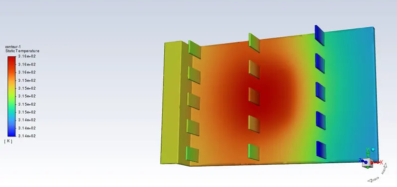
- Potential Hotspot
For Velocity 5 m/s with refined mesh
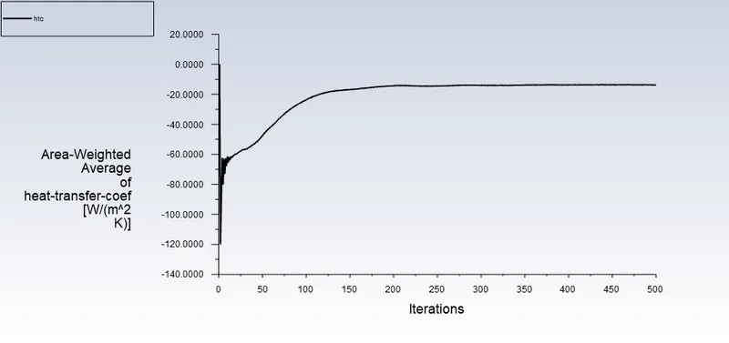
- Heat Transfer Coefficient attained by the processor
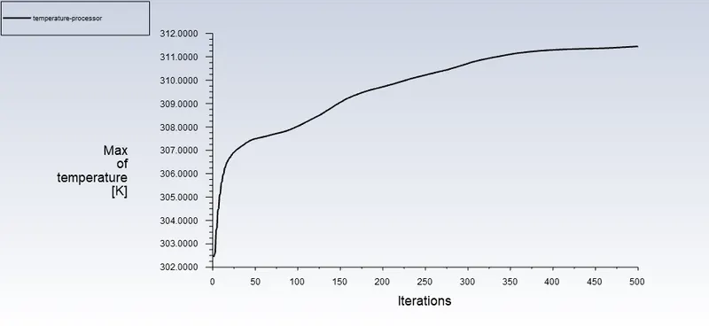
- Maximum Temperature attained by the processor
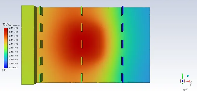
- Potential Hotspot
Prove that the simulation has achieved convergence with appropriate images and plots.
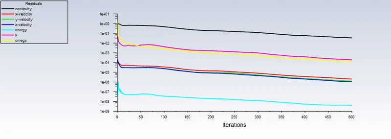
From the above plots, we can observe that the residual plot has gone to 1 e-3, which is a potential condition for the solution to attain convergence criteria.
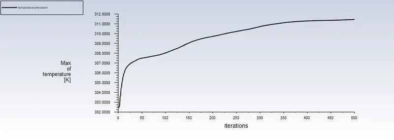
From the above temperature plot, we can observe that the plot is not fluctuating anymore, and with this, we can conclude that the temperature plot has reached a convergence state.
Identify potential hotspots on the model
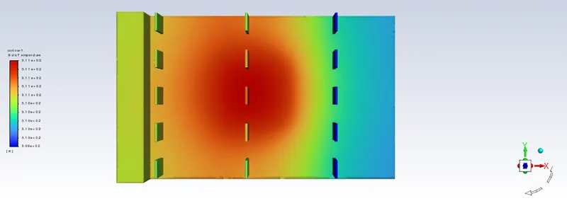
The red zone around the processor indicated the potential hotspot of the model and fins are provided to cool down the region near the hotspot.
Maximum temperature and heat transfer coefficient attained by the processor.
| Velocity ( m/s) | Temperature (K) | Heat Transfer Coefficient [W/(m^2 K)] |
| 1 m/s | 336.78825 | -0.30590405 |
| 3 m/s | 316.05295 |
-6.0197558 |
| 5 m/s | 311.44358 | -13.705061 |
Conclusion
- The red zone around the processor indicated the poential hotspot of the model and fins are provided to cool down the region near the hotspot.
- The negative values of heat transfer coefficient indicates that the heated air is leaving the system
- We can observe that with the increase in velocity, our temperature values around the processor is decreasing and similarly our heat transfer coefficient values are also increasing