Week 10 - Battery Thermal Management System(BTMS)
Aim: To perform the heat transfer analysis on the 4x2 cylindrical lithium ion battery with heat generation boundary conditions for different cases and compare the results.
Objective:
- Explain why battery cooling is needed. And give a brief description about various techniques for
battery cooling. - Perform Mesh independent study for any one case and based on your judgment use the more
suitable model for further cases. - Run the simulation by varying the velocity of air as 3, 5 and 10m/sec and discuss the results.
- Find out the maximum temperature and heat transfer coefficient obtained by the battery.
- Based on the results and on your judgment, select one case (3,5 or 10 m/s) and vary the space
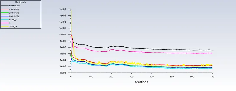
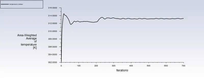
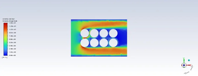
between the batteries as 2, 4 and 6 mm, then discuss the results. - Prove that the simulation has achieved convergence with appropriate images and plots (Velocity and
temperature contour plots on the cut planes). - Create the animation to observe the temperature distribution and velocity vector.
- Summarize the results in tabulation/ graphical form.
- Identify potential hotspots on the model.
- State the inferences based on the results.
Theory
Explain why battery cooling is needed. And give a brief description about various techniques for
battery cooling.
- Lithium-ion batteries and lithium polymer batteries are the most commonly used types of batteries in electric vehicles in which overheating is considered to be one of the primary causes of accelerated battery degradation in electric vehicles.
- Heat generation affects the battery, causing its performance to deteriorate over time.
- The elevated temperature in the battery causes battery fluid evaporation and an irreversible harm to the battery's internal structure.
- The accelerated electric currents produced by direct current fast charging and rapid charging of the battery are bad for battery health.
- As the temperature rises, battery life, electric car driveability, and fuel economy suffer.
- In electric vehicles, a battery cooling system is crucial because of the overall thermal effect on the battery.
Battery Thermal Management System (BTMS)
- A battery Thermal Management System (BTMS) in the electric car delivers crucial data such as:
- Thermal Protection
- Over and Under voltage protection
- Over-current Protection
- Prolong battery life
- Cell Balancing
- SoC and SoH calculation
- Communication with all battery components
- Data acquisition and analysis
The different battery cooling methods are as follows
- Air Cooling
- Liquid Cooling
- Heat pipe
- Phase Change Material (PCM)
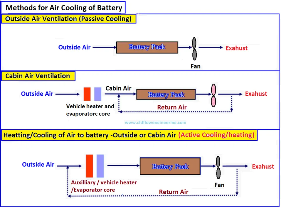
Air Cooling
- Air is readily available for cooling and it's frequently used in a number of industries. However, due to its limited heat capacity and thermal conductivity, air is ineffective as a coolant.
- Cooling can be accomplished by either forced convection (active cooling) or natural convection (passive cooling).
- Natural convection cooling is only suitable for low-density batteries, and blowers/fans are frequently used to boost the convection heat transfer rate.
- Electric vehicles such as Toyota Prius Prime and Nissan Leaf employed air cooling.
Liquid Cooling
- Liquid coolants have a high convection heat removal rate due to its higher density and high heat capacity
- It is more compact when compared with air cooling system
- It doesnt generate a lot of noise
- It is divided into two main categories i.e Direct Cooling and Indirect Cooling
Indirect Liquid Cooling
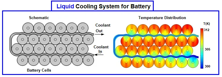
- Water has been used as an effective coolant in several industrial applications, but the main issue is the short-circuit potential for direct cooling of batteries. To avoid this issue,indirect methods of cooling are employed.
- EV Giants such as General Motors(GM) and Tesla are using indirect way of liquid cooling in there cars
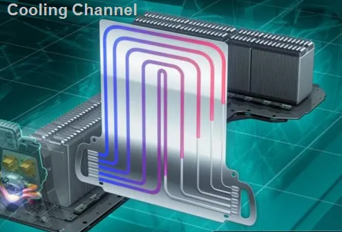
- General Motors uses cold plates between each prismatic cells.The cold plates has several micro-channels which helps in convection heat removal process of batteries
- Tesla uses wavy tubes which is placed between cylindrical cells
- To fill the spaces between the battery cells and the cooling ducts, thermally conductive and electrically insulated materials are utilised.
Chevrolet Cooling System
- It is made up of a huge number of micro-channels placed in metal plates to carry out coolant circulation.
- To remove the heat, the plate is sandwiched between two battery packs.
Direct Liquid Cooling
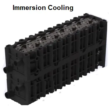
- It is also known as Immersion Cooling as it covers up the entire surface of the cell and enables unifrom cooling
- It also helps in removing hot or cold spots in the cell and also helps in improving the performance of the cells.
- Immersion cooling is widely used for data center servers and high-power electronics devices
- Immersion cooling is used in high perfomance Electric Vechiles and racing Electric Vechiles and the fluid has a boling point in between 60-80 C to prevent overheating and thermal runaway of the cells.
- Electric Vechiles such as Auid R8 Tron, Ford Focus, GM Chevrolet Bolt etc
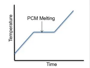
Phase change Material (PCM) Cooling
- It absorbs heat significantly due to its high latent heat during the discharge phase of battery
- It can also be used as a paraffin which has a melting point in the range of 32-38 degree celsius and it is mixed with graphite flakes to improve thermal conductivity
- It also acts a shield incase of thermal runaway
- The equation used for PCM is `V*ρ*L = P*t`
- where V = Volume of the cell(m^3), ρ = Density of the cell(kg/m^3) , L =Latent heat of fusion ( per kg) , P =Power Absorbed ( Watts) and t = Time of power absorbtion ( seconds)
Heat Pipe
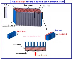
- It has a wide range of industrial application due to its efficient cooling and thermal management
- The heat pipes are used to extract heat from the battery which provides efficient heat transfer at low power consumption
- The heat is transferred through the latent heat of vapourization from evaporator to the condensor
Geometry Preparation
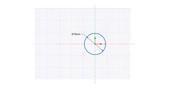
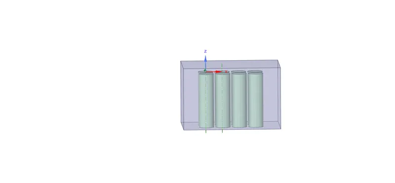
- Create a circle of 18 mm diameter
- Conversion our geometry as a surface

- Pattern Creation
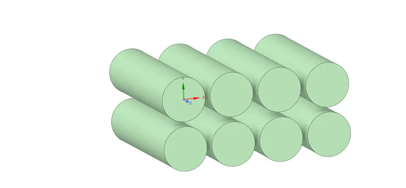
Design -> Linear Pattern -> Pattern Type -> 2-Dimensional Select the Geometry -> Select the Axis -> X-Count -> 4 -> Y-count -> 2
X Pitch and Y Pitch -> 20 mm each -> Confirm Selection

- Cylinderical Battery Geometry Creation
Pull Tool -> Select the Geometry -> Extrude it for 65 mm
- Creating our Enclosure
Prepare -> Enclosure -> Select the geometry -> Uncheck Symmetric Dimensions -> Give Proper Dimensioning -> Confirm Selection
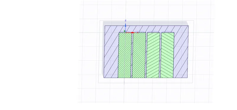
- Check For Interference
Prepare -> Interference -> Select the geometry -> Confirm Selection to fix the issue.
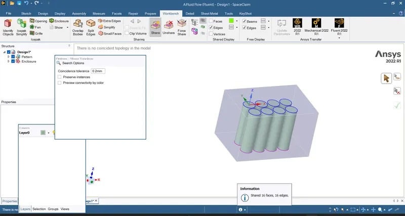
- Share Topology
Workbench -> Share -> Uncheck Preserve Instances -> Confirm Selection
Meshing The Geometry
Named Selection
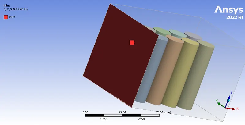
Inlet
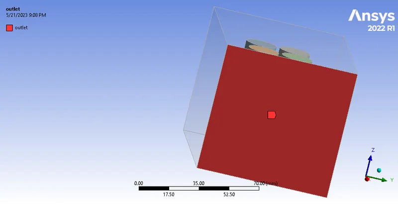
outlet
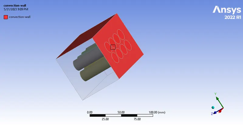
convection-wall
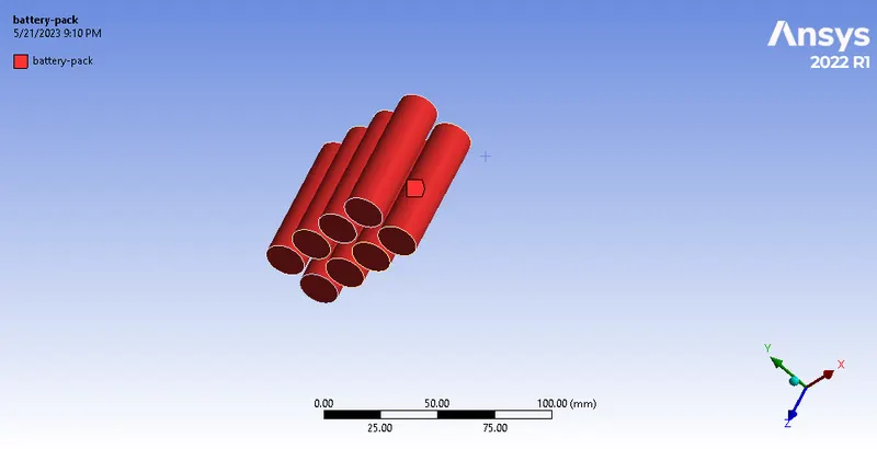
Battery-Pack
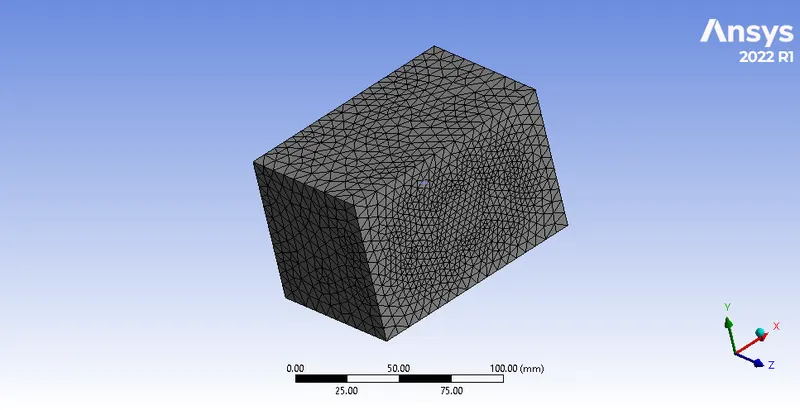
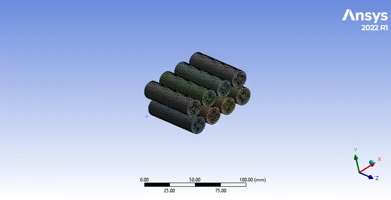
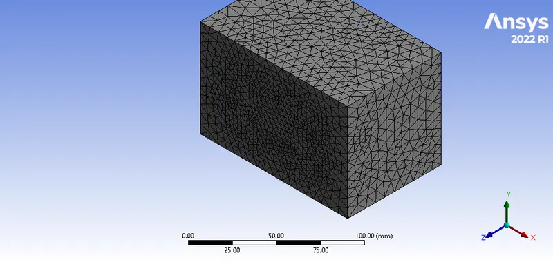
Meshed Geometry
Outer Enclosure
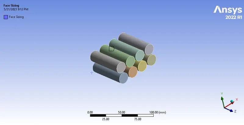
Face Sizing
Edge Sizing
Inflation-Layers
Mesh Metrics
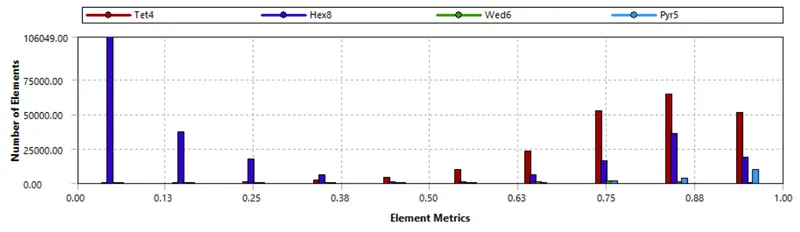
Mesh Counts

Setup
- Solver Type -> Pressure-Based
- Solver Time -> Steady
- Viscous Model -> K-Omega-SST
- Materials Used -> Fluid -> Air -> Solid -> Lithium and Aluminium
- K-Omega Model is preffered over other turbulence modelling methods in whenever we are concerned about the inner parts of the boundary layer which makes the model directly usable in the viscous sub layer regions
- K-Omega Model can perform better in the near wall regions due to its elliptical nature
- Shear-Stress-Transport(SST) Model is a low Reynolds Number Model which is integrated through the boundary layer to the wall and it also allows Dirichlet (no-slip-condition) to be applied to velocity.
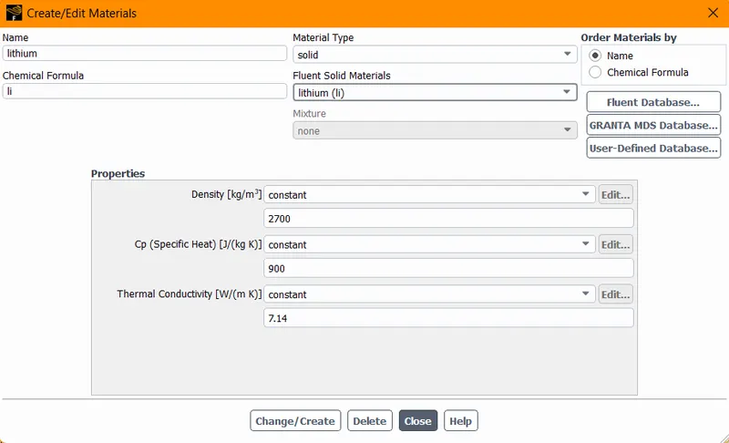
- Cell Zone Conditions
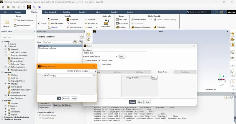
- Battery-pack -> solid -> lithium -> Enable Source Term -> 604577 W/m^3 -> Confirm Selection
- Calculations
- Power Density of the battery = Heat generation rate of the battery / Volume of the battery
- Heat Generation rate of the battery = 10 watts(assumed value)
- Power Density of the battery = (𝝅/4)*(Diameter)^2*(Length) where as Diameter = 18 mm = 18 e-3 m and Length = 65 mm = 65 e-3 m
- Power Density of the battery = (𝝅/4)*(0.018)^2*(0.065) = 604577 Watts/m^3
- Enclosure -> fluid -> air
- Boundary Conditions
- Inlet -> Velocity-inlet ->Velocity -> 3 m/s -> Temperature -> 300k
- Outlet -> Pressure-Outlet
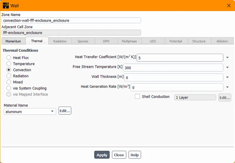
- Convection Wall Enclosure ->Thermal Conditions -> Convection Heat Transfer Coefficient -> 5 W/m^2k -> Material -> Aluminium
- Solution Method -> Coupled
- Initialization Method -> Standard Initialization -> Compute from inlet
Post Processing
- Perform Mesh independent study for any one case and based on your judgment use the more
suitable model for further cases.
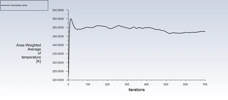
Case 1 BaseLine Mesh with Velocity of 3 m/s and with a pitch of 2 mm without inflation layers
- Mesh Size of default 8.0049 mm
- Mesh Metrices
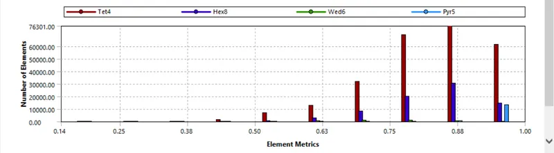
- Meshing Statistics

Case 2 BaseLine Mesh with Velocity of 3 m/s and with a pitch of 2 mm without inflation layers
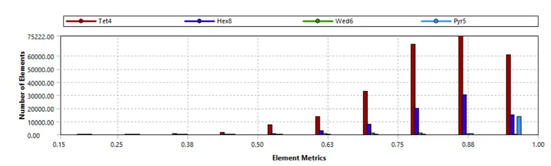
- Mesh Size of 7 mm
- Mesh Metrics
- Meshing Statistics

Case 3 Refined Mesh with Velocity of 3 m/s and with a pitch of 2 mm inflation layers,edge sizing and face sizing
- Mesh Size of 7 mm
- Face Sizing of 6 mm
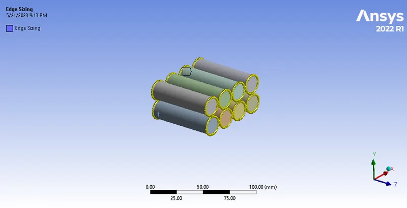
- Edge Sizing of 36 edges(360/10)
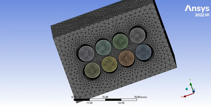
- Inflation Layer of 5 mm with 12 inflation layers
- Mesh Metrics
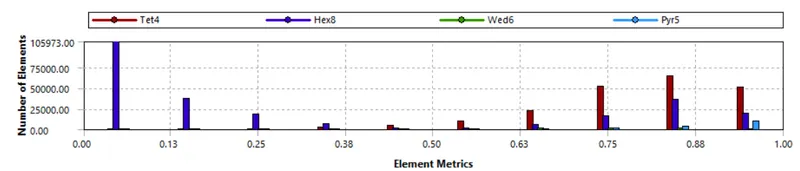
- Mesh Statistics

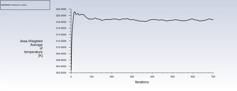
Mesh Independent Study
| Mesh Size | Nodes | Elements | Maximum Temperature | Heat Transfer Coefficient |
| Baseline Mesh Size of 8.0449 mm(default) without inflation layers | 127571 | 352217 |
347.94752 |
-43.065473 |
| Baseline Mesh Size of 7mm without inflation layers | 126796 | 351036 | 348.1769 | -43.00145 |
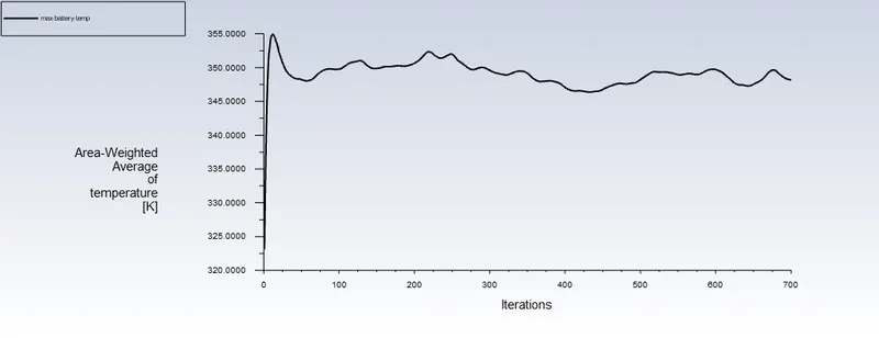
| Refined Mesh Size of 7mm with inflation layers | 287300 | 464348 | 318.59334 | -36.196533 |
- We can observe that the Refined Mesh Condition offer the lowest possible temperature with an adequate heat transfer coefficient.As a result, we will proceed with the Refined Mesh Condition for further simulations.
- Run the simulation by varying the velocity of air as 3, 5 and 10m/sec and discuss the results.
Case 1 Refined Mesh with Velocity of 3 m/s and with a pitch of 2 mm inflation layers,edge sizing and face sizing
- Mesh Size of 7 mm
- Face Sizing of 6 mm
- Edge Sizing of 36 edges(360/10)
- Inflation Layer of 5 mm with 12 inflation layers
- Mesh Metrics
- Mesh Statistics
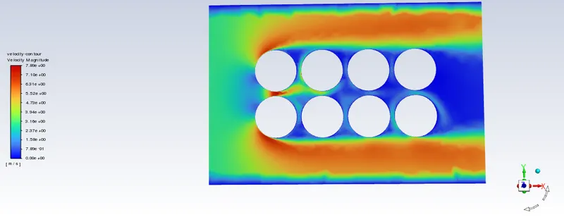
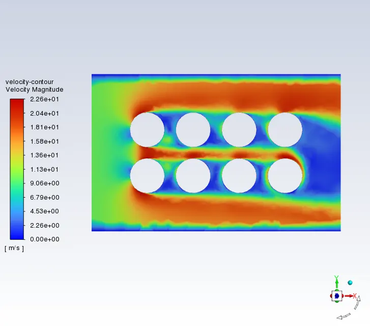
Velocity-Contour
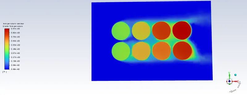
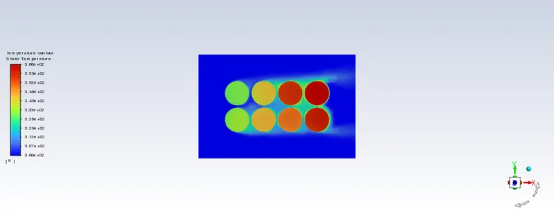
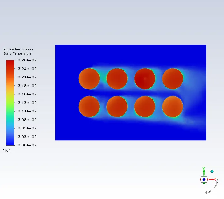
Temperature-Contour
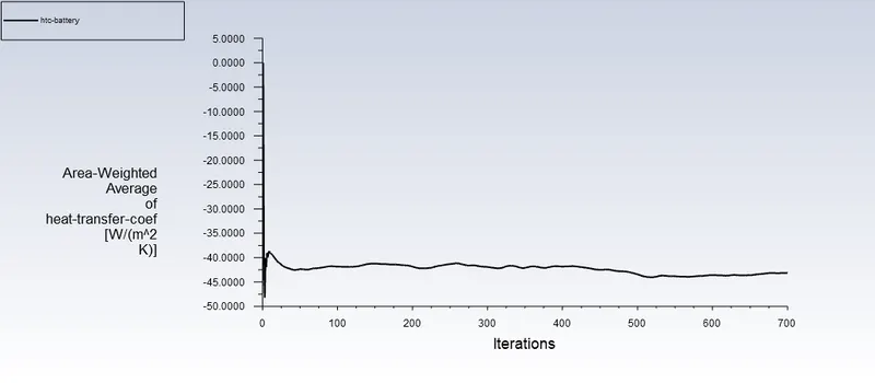
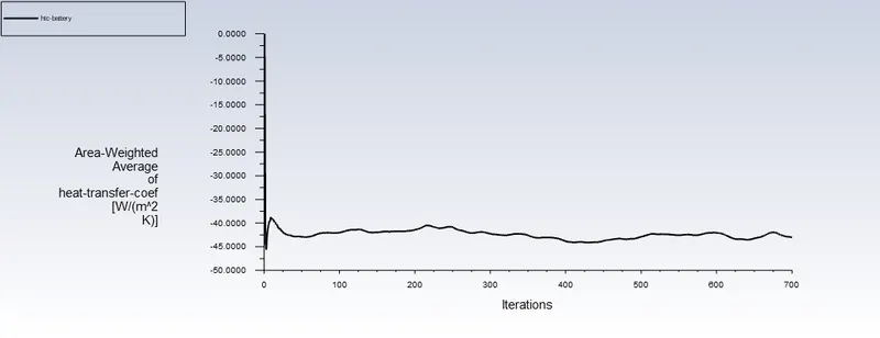
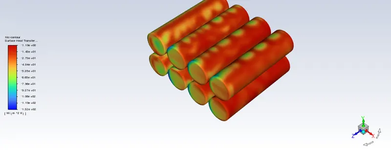
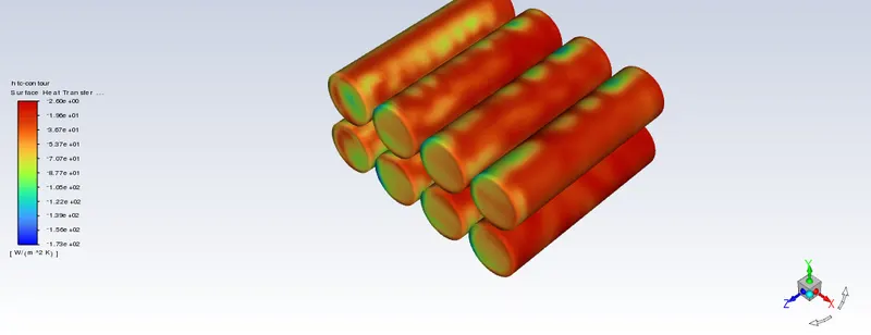
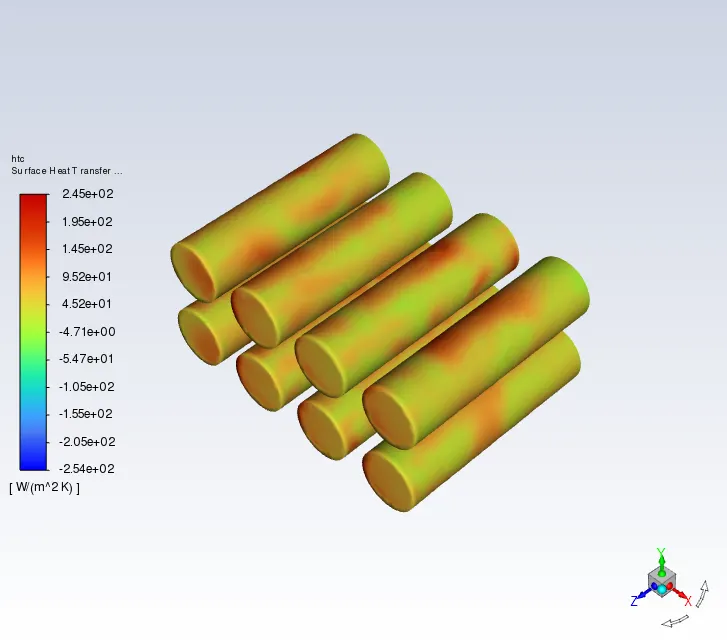
Heat Transfer Coefficient Variation at the battery
Case 2 Refined Mesh with Velocity of 5 m/s and with a pitch of 2 mm inflation layers,edge sizing and face sizing
Case 3 Refined Mesh with Velocity of 10 m/s and with a pitch of 2 mm inflation layers,edge sizing and face sizing
| Serial No | Velocity(m/s) | Pitch(mm) | Maximum Temperature | Heat Transfer Coefficient |
| 1 | 3 m/s | 2 | 318.59334 | 36.196533 |
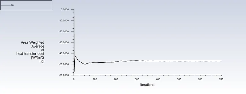
| 2 | 5m/s | 2 | 313.25538 | 47.096174 |
| 3 | 10m/s | 2 | 308.10332 | 66.88285 |
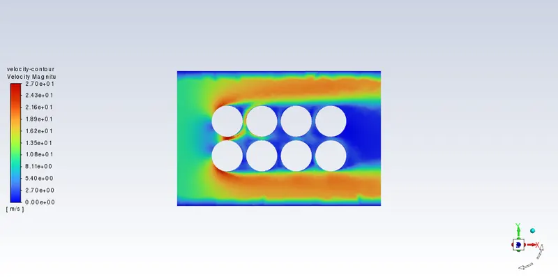
- From the above results, we can conclude that the temperature is decreasing with increase in velocity and similarly Heat Transfer Coefficient value is also increasing with increase in velocity.
- So, we are finalizing 10 m/s as our velocity for further simulations.
- Based on the results and on your judgment, select one case (3,5 or 10 m/s) and vary the space
between the batteries as 2, 4 and 6 mm, then discuss the results.
- We have finalized 10 m/s as our final geometry on our judgement
Case 1 Refined Mesh with Velocity of 10 m/s and with a pitch of 2 mm inflation layers,edge sizing and face sizing
Case 2 Refined Mesh with Velocity of 10 m/s and with a pitch of 4 mm inflation layers,edge sizing and face sizing
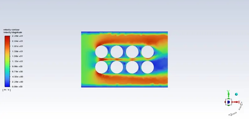
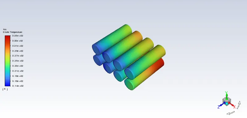
Case 3 Refined Mesh with Velocity of 10 m/s and with a pitch of 6 mm inflation layers,edge sizing and face sizing
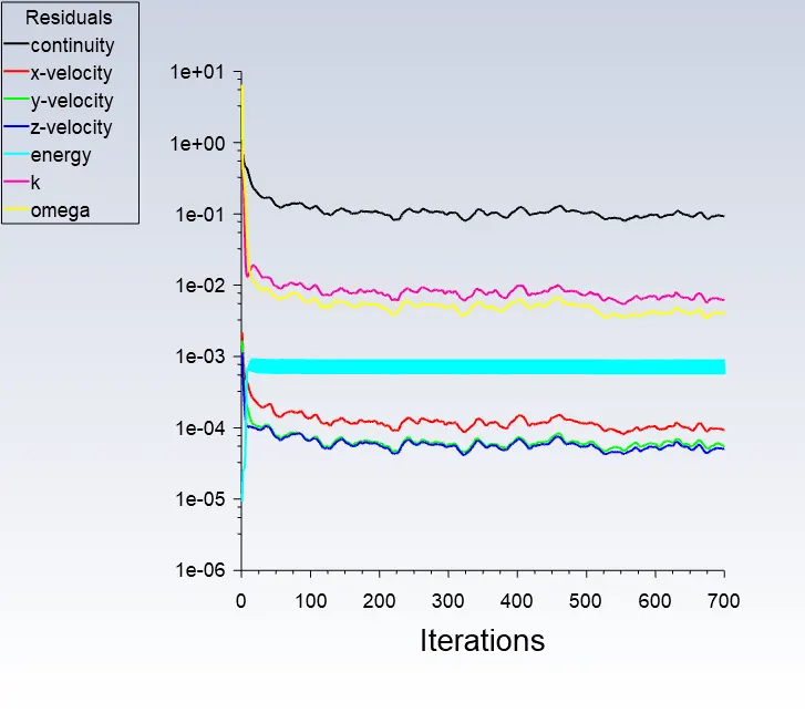
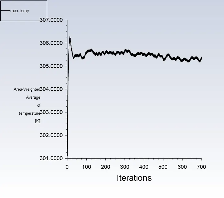
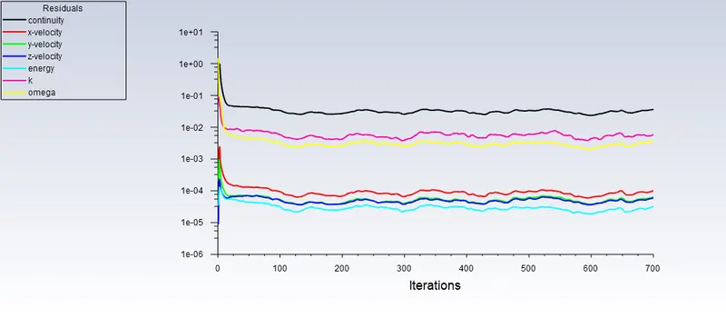
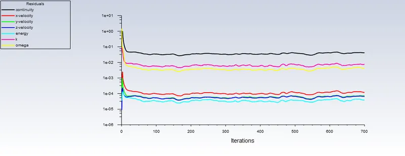
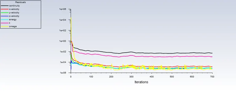
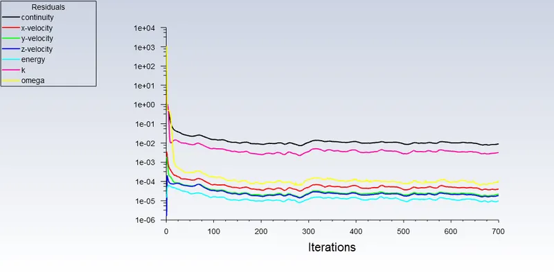
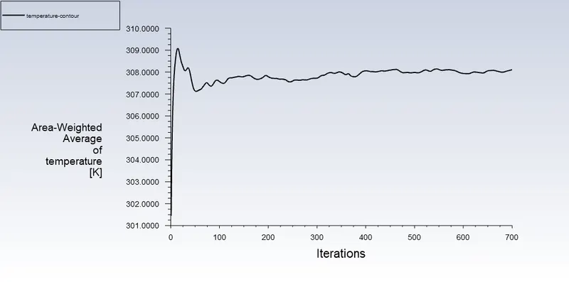
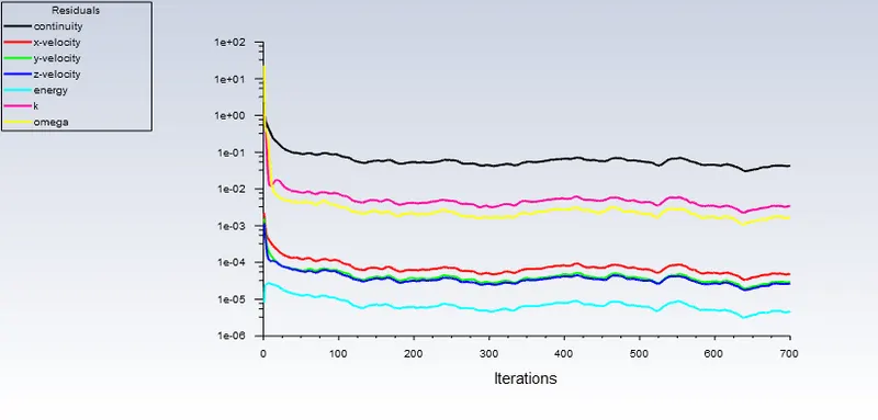
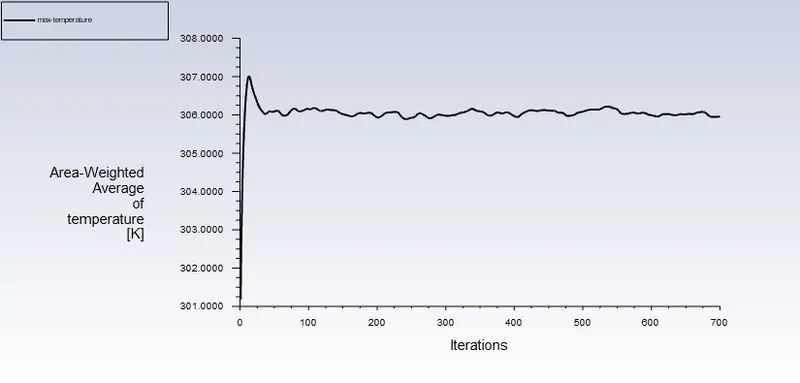
- Prove that the simulation has achieved convergence with appropriate images and plots
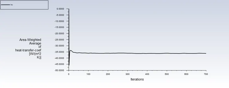
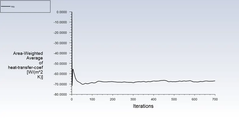
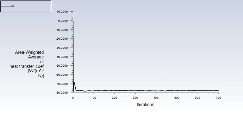
From the above heat transfer coefficient plot, we can observe that the plot is not fluctuating anymore, and with this, we can conclude that the heat transfer coefficient plot has reached a convergence state.
- Create the animation to observe the temperature distribution and velocity vector.
Results in Tabulation Form
| Velocity(m/s) | Pitch(mm) | Maximum Temperature | Heat Transfer Coefficient |
| 10 | 2 | 308.10332 | 66.88285 |
| 10 | 4 | 305.95706 | 77.265165 |
| 10 | 6 | 305.39888 | 79.033204 |
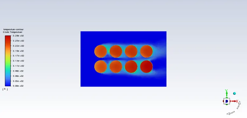
- Identify potential hotspots on the model.
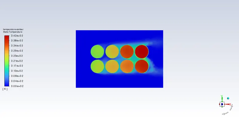
The red zone around the battery indicates the potential hotspot of our battery model, and we can use different cooling methods for better efficiency and longevity of our battery.
- Conclusions
- The red zone around the battery indicated the poential hotspot of the model and various cooling methods are used to cool down the region near the hotspot.
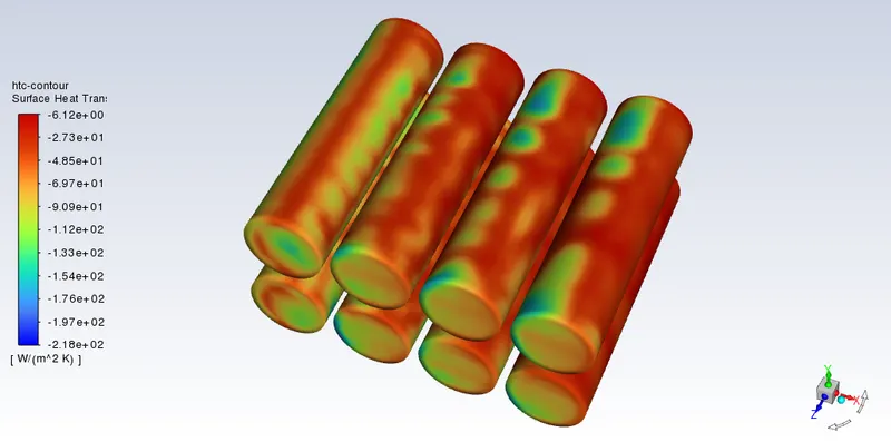
- The negative values of heat transfer coefficient indicates that the heated air is leaving the system
- With the increase in velocity with constant pitch value of 2mm, we can observe that our temperature values are decreasing whereas, the heat transfer coefficient values are in increasing nature
- We also observed that the heat transfer coefficient value is increasing with increase in our pitch values with constant velocity of 10 m/s