Week 2 Challenge : Surface meshing on a Pressure valve
Aim: To prepare a detailed report on the geometrical errors cleanup & meshing of the pressure valve.
Objective: To prepare a detailed report on geomtrical errors cleanup & meshing of pressure valve using three different target lengths of 1 mm, 3 mm & 5 mm and using Element type = Tria.
Introduction :
Pressure Relief Valve
Pressure Valve(Pressure Relief Valve) is a safety device designed to protect a pressurized vessel or system during an overpressure event.
An overpressure event refers to any condition that would cause pressure in a vessel or system to increase beyond the specified design pressure or maximum allowable working pressure (MAWP).
Many electronic, pneumatic, and hydraulic systems exist today to control fluid system variables such as pressure, temperature, and flow. Each of these systems requires a power source of some type, such as electricity or compressed air, in order to operate. A pressure relief valve must be capable of operating at all times, especially during a period of power failure when system controls are nonfunctional. The sole source of power for the pressure relief valve, therefore, is the process fluid.
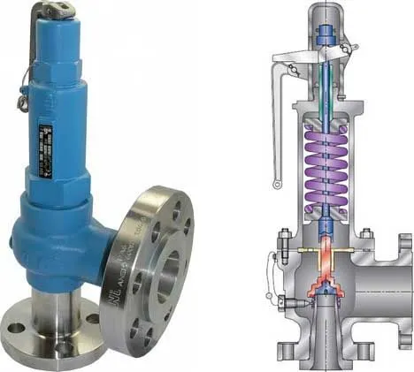
Spring-loaded pressure relief valve
The basic spring-loaded pressure relief valve has been developed to meet the need for a simple, reliable, system-actuated device to provide overpressure protection.
The image on the right shows the construction of a spring loaded pressure Relief Valve.
The Valve consists of a Valve inlet or nozzle mounted on the pressurized system, a disc held against the nozzle to prevent flow under normal system operating conditions, a spring to hold the disc closed, and a body/Bonnet to contain the operating elements. The spring load is adjustable to vary the pressure at which the Valve will open.
When a pressure Relief Valve begins to lift, the spring force increases. Thus system pressure must increase if lift is to continue. For this reason pressure Relief Valves are allowed an overpressure allowance to reach full lift. This allowable overpressure is generally 10% for Valves on unfired systems. This margin is relatively small and some means must be provided to assist in the lift effort.
Function Of Pressure Valve
Pressure relief valves have higher flow capacities than pressure reducing valves because pressure relief valves have to be capable of directing all flow to the tank.
Pressure relief valves are used in hydraulic systems to limit the system pressure to a specific set level. If this set level is reached, the pressure relief valve responds and feeds the excess flow from the system back to the tank.
A pressure relief valve regulates system pressure proportionally. It guards against the harm that excess pressure can do to pressure-sensitive equipment.
Before the pressure in the system reaches dangerous levels, a relief valve starts to open.
Pressure increases are slowed.
When system pressure reaches the relief valve's setpoint, the valve is fully open. It stops the pressure in the system from increasing.
Procedure:
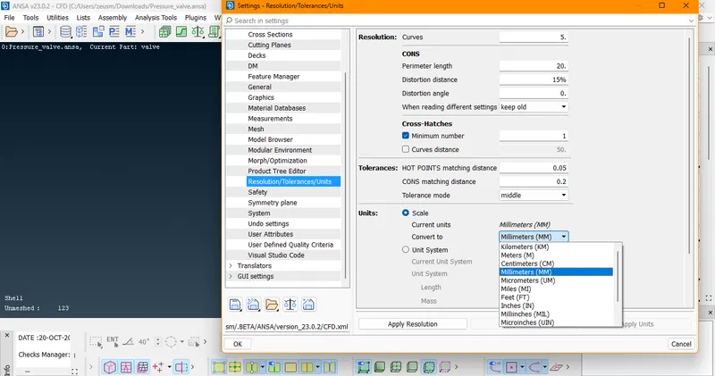
After importing the raw geometry, the first thing we should check are the units.
We can perform this step under Tools -> Settings -> Resolution/Tolerance/Units
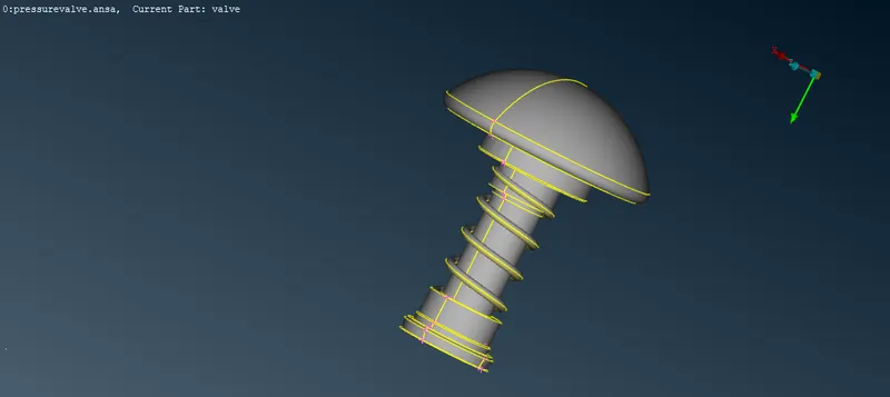
Then we should check for the orientation of the geometry.
Here, we need to check whether the analysis is internal flow analysis or external flow analysis and then we can decide which side should be grey in color and which should be yellow in color
While using ANSA, Grey Color represent the positive side and the side where the fluid is interacting and similarly Yellow Color represent the negative side.
As we are performing internal flow analysis, grey should be the inner or fluid-interacting side.
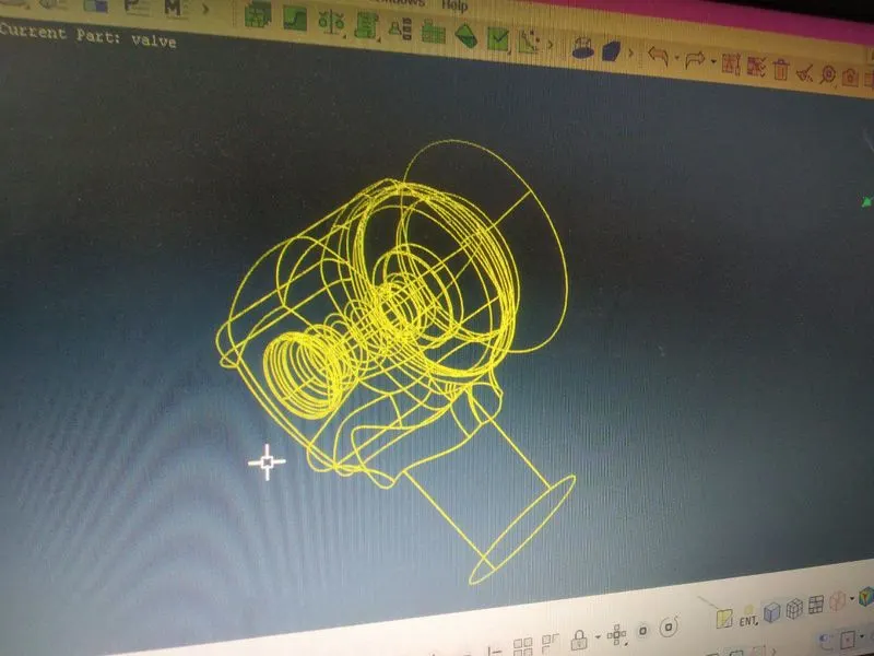
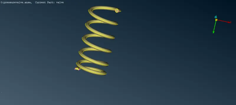
In the inner part of geometry there is a spring column and the valve head which falls under the fluid interacting and we need to take care of it and assign it as grey color also..
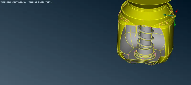
Now, our main aim is to create a water-tight geometry which will be required for further meshing and solving process....
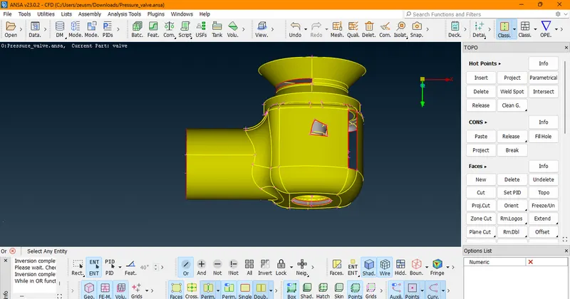
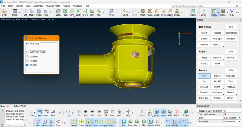
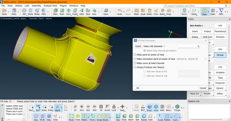
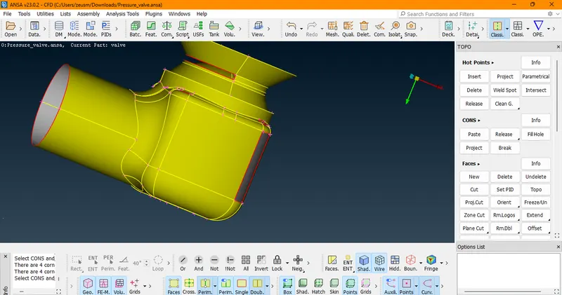
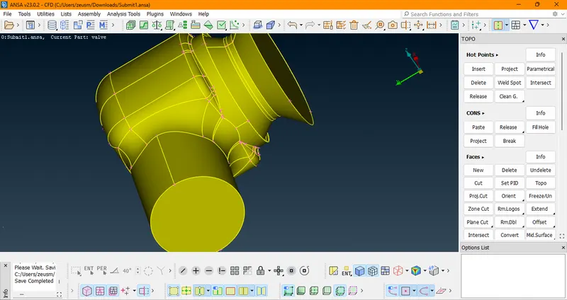
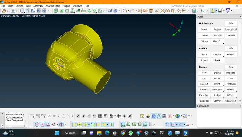
Here we can see the geometry fix applied using the Fill Hole Option and still it has its limitations. At the end, we need to check the geometry and decide accordingly.
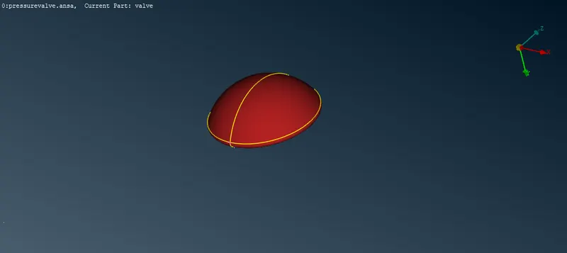
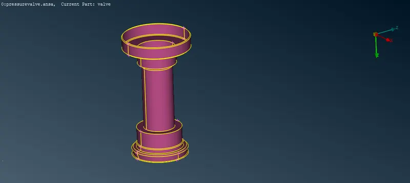
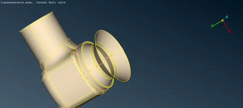
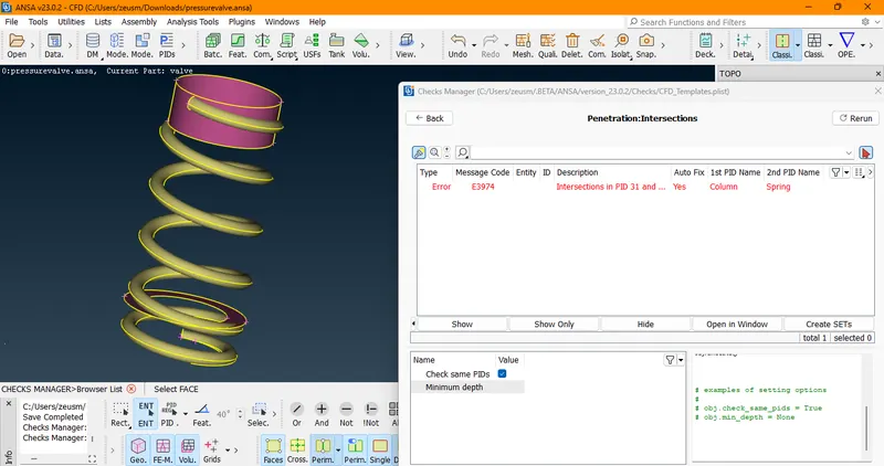
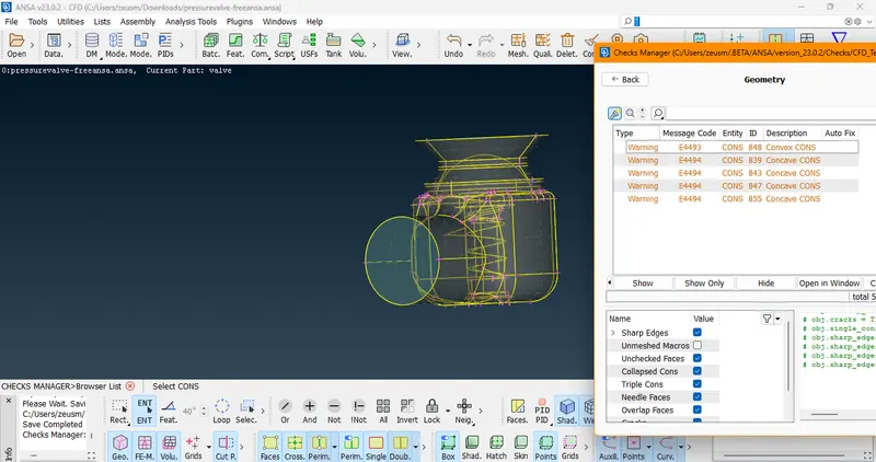
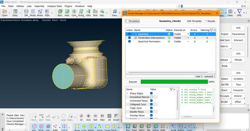
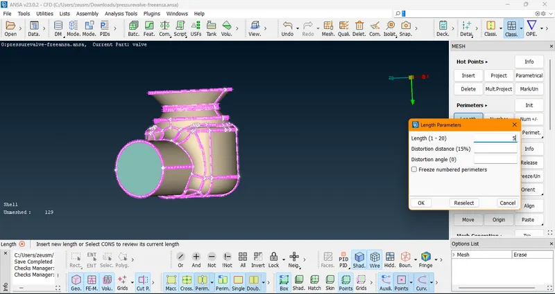
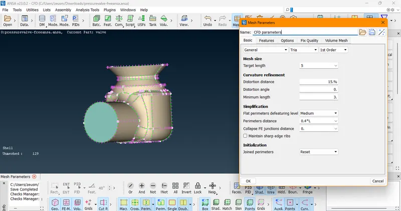
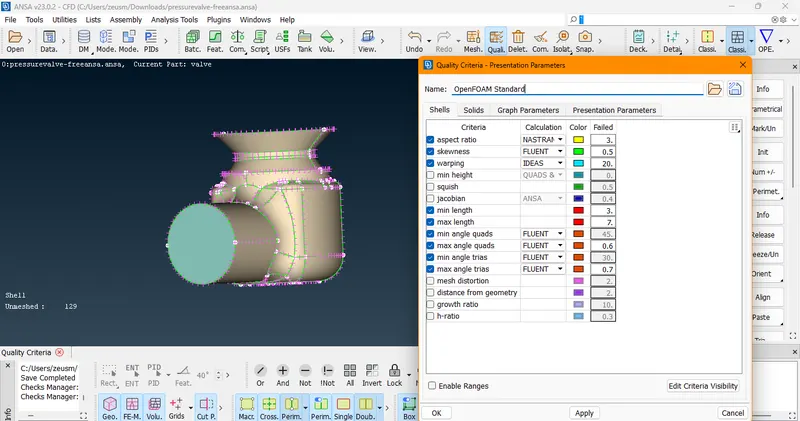
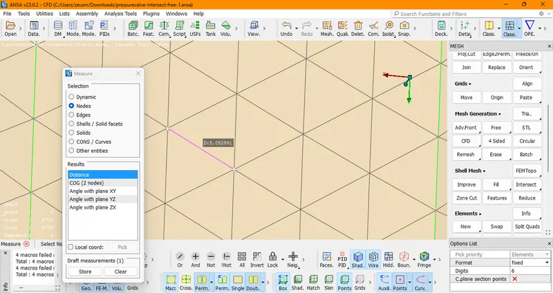
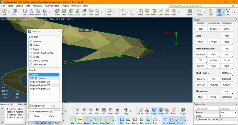
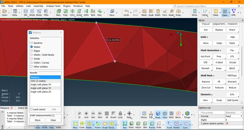
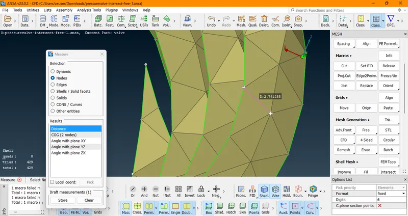
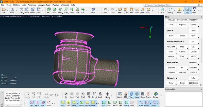
- From the aforementioned 3 situations, it can be inferred that case 3, with a target length of 1 mm, defeaturing is minimal to nonexistent, and every component geometry has been preserved.
- Hence, case 3 gives the best results. On the other hand, it lengthens the computational time.
- To decrease the computational time, the number of elements needs to be decreased without defeaturing. To achieve this, the components whose size is less than or equal to the mesh size need to be meshed individually with different mesh sizes.