Week 4 - CHT Analysis on Exhaust port
Aim : To Perform CHT Analysis on Exaust Port.
Objectives : To perform CHT Analysis on Exaust Port with a velocity of 5m/s with air as the working fluid.
- Give a brief description of why and where a CHT analysis is used.
- Maintain the y+ value according to the turbulence model and justify the results.
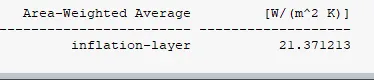
- Calculate the wall/surface heat transfer coefficient on the internal solid surface & show the velocity & temperature contours in appropriate areas.
- How would you verify if the HTC predictions from the simulations are right? On what factors does the accuracy of the prediction depend on?
Theory : CHT analysis refers to "conjugate heat transfer analysis," and it allows us to perform simulations of heat transfer between solid and fluid domains with exchange of thermal energy at the interfaces between them. This type of heat transfer analysis includes both conduction( between solids) and convection (between fluids) heat transfer, and it is also applicable in the case of both natural and forced convection processes.
- Give a brief description of why and where a CHT analysis is used.
- CHT analysis refers to "conjugate heat transfer analysis," and it allows us to perform simulations of heat transfer between solid and fluid domains with exchange of thermal energy at the interfaces between them. This type of heat transfer analysis includes both conduction( between solids) and convection (between fluids) heat transfer, and it is also applicable in the case of both natural and forced convection processes.
- It is used in case of electronics cooling, heat exchangers and heavy industrial machinery etc.
Conduction :
- It is the process of transmitting energy from one medium particle to another through direct contact between particles.
- It is goverened by Fourier's Law of Conduction.
- `begin{array}{l}Q_{cond}=kAfrac{T_{1}-T_{2}}{Delta x}=-kAfrac{Delta T}{Delta x}end{array}`
- A is cross sectional area
- ΔT is the temperature difference
- Δx is the distance between our two ends.
Convection :
- It is the movement of fluid molecules from higher temperature zones to lower temperature zones
- It can occour in both liquid and gases
- It can be natural convection or forced convection process
- Natural convection occurs owing to buoyant forces induced by differences in densities caused by temperature differences.
- When external sources such as fans and pumps are employed to create convection, this is referred to as forced convection.
- `Q=h A Delta T`
- where Q = heat transfer rate
- h = convection heat-transfer coefficient
- A = exposed surface area
- Delta T = temperature difference
2. Maintain the y+ value according to the turbulence model and justify the results.
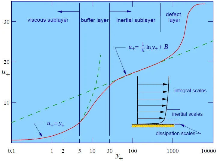
- For CHT Analysis, we are using K-Omega-SST Model for which the y+ value is taken in the range of 1 < y+ <5
- Y+ provides a relation between frictional velocity, absolute distance from the wall to cell and kinematic viscosity.
- If the y+ value is in range of 1 < y+ <5 its falls in the range of viscous sub-layer and if it in range of 30 < y+ < 300 it falls in the range of Log-Law Layer.
- Viscous sub layer is used for getting better results in the near wall function.
- We refer 'Smoothness' Quality Criteria for smooth transition fron one cell to another.
- For calculating y+, we have assumed the value in range with a flat plate as our reference, and if we encounter a curve surface, our y+ value will start deviating from our calculated value as our velocity is changing, and with the change in velocity, Reynolds number will also be changing (Reynolds number is directly proportional to free stream velocity), and because of Reynolds number, coefficient of friction will also be changing, and with coefficient of friction, our wall shear stress will start changing, and with wall shear stress, our frictional velocity will also start fluctuating, and as y+ is proportional to frictional velocity, our y+ value will also start deviating.
- Y+ depends heavily on geometrical shape.
- It is advisable to take a lower value of y+ as it helps the CFD Simulations to fetch better results and converge faster.
Geometry Preparation
- Geometry Import
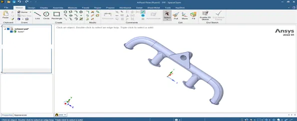
So here is our Raw Cad Geometry imported in SpaceClaim.
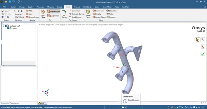
- Fix Duplicate Edges
Repair -> Extra Edges(indicated with red lines) -> Remove those edges and fix the issue.
- Fluid Volume Extraction
Prepare -> Volume Extract -> Select all the edges -> Confirm Selection
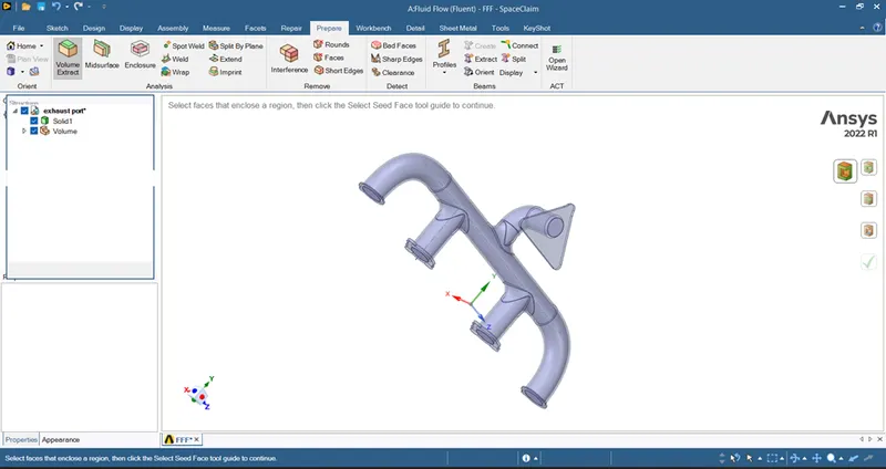
- Sharing Topology
Workbench -> Share -> Confirm selection to fix the issues
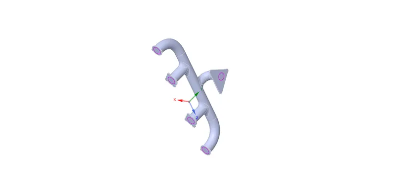
Meshing The Geometry
- Named Selections
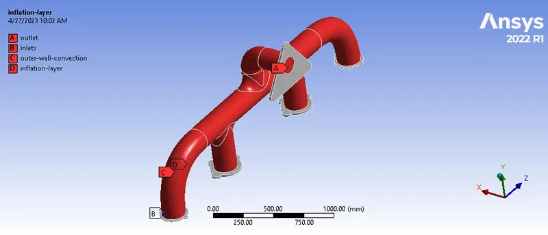
- Edge Sizing at Outlet
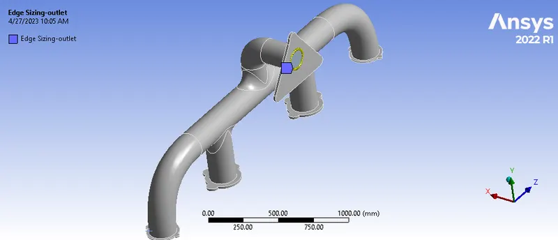
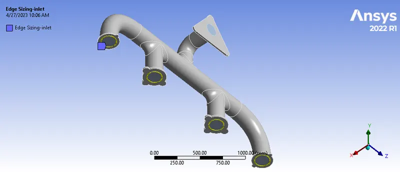
- Edge Sizing At Inlets
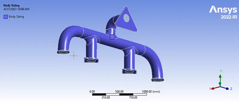
- Body Sizing
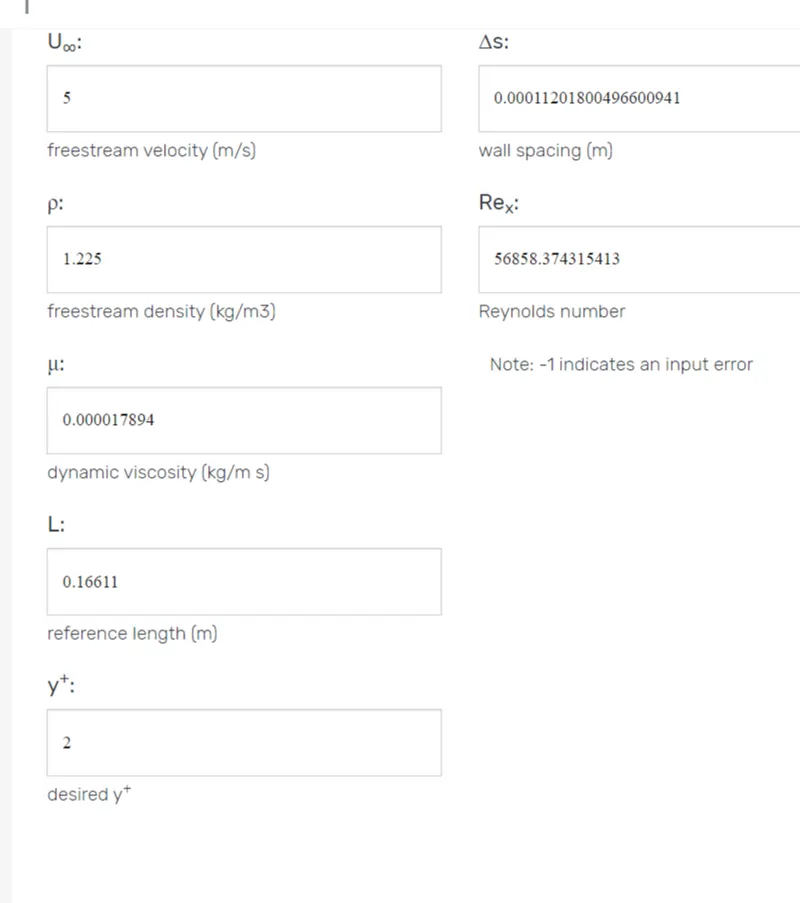
- First Layer Height Calculation
- Free Stream Velocity = 5 m/s
- Characteristics Length = Diameter of the circular region at inlet = 0.16611 meters
- Free Stream Density = 1.225 kg/m^3
- Dynamic Viscosity = 1.7894 E - 5 kg/m-s
- Reynolds Number = 56858.374315413
- First Layer Height = 0.00011201800496600941
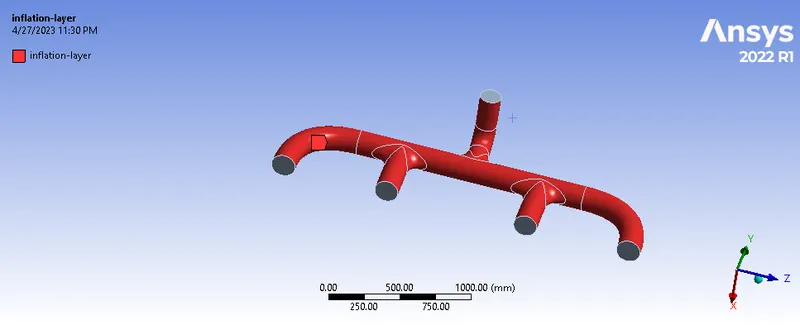
- Inflation Layers
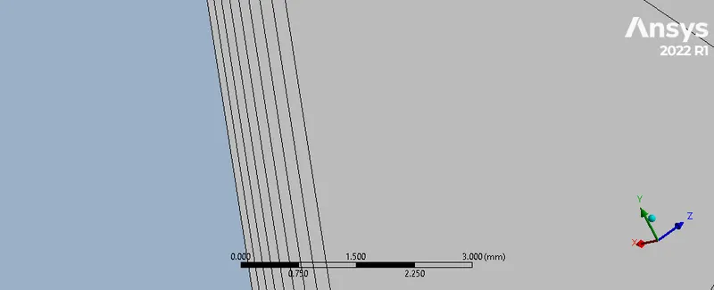
- Final Geometry After Meshing
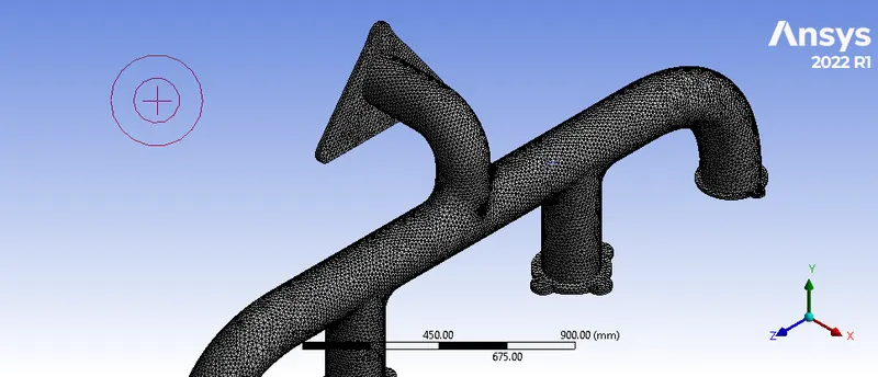
Setup
- Solver Type : Pressure Based
- Solver Time : Steady State
- Energy : On
- Turbulence Model K-Omega-SST
- Material -> Fluid -> Air
- Inlet Velocity -> 5 m/s
- Outlet -> Pressure Outlet
- Outer Wall Convection -> Wall -> Convection = 20 W/m^2-K
- Internal solid Surface -> Wall Boundary Condition
- Solving Method -> Coupled
Post-Processing Results
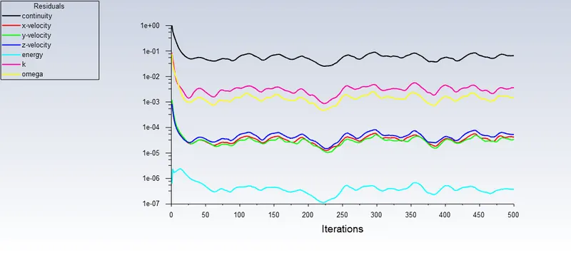
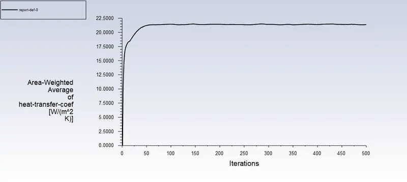
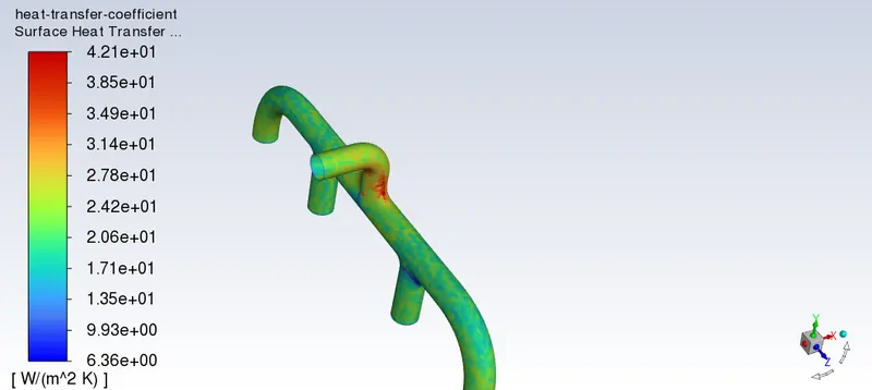
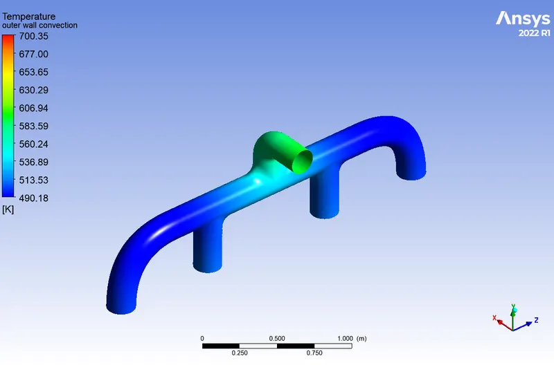
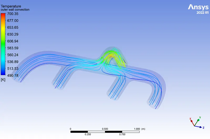
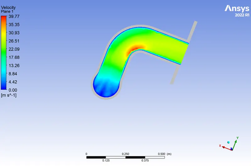
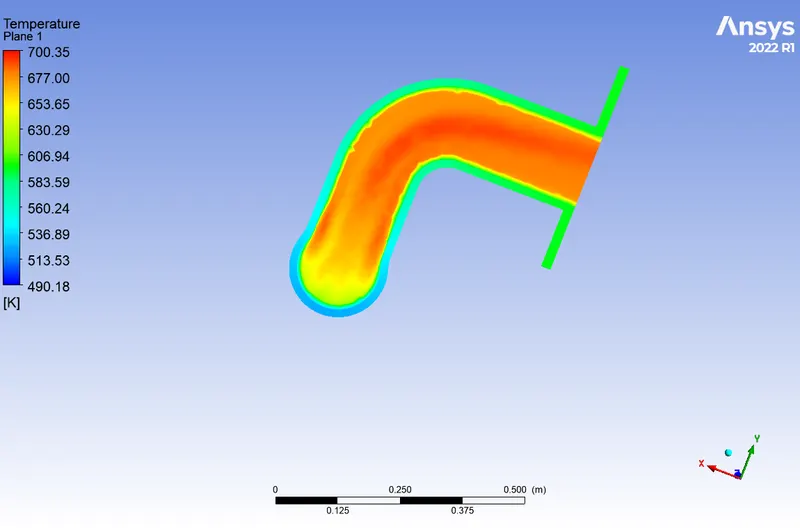
Wall Heat Flux
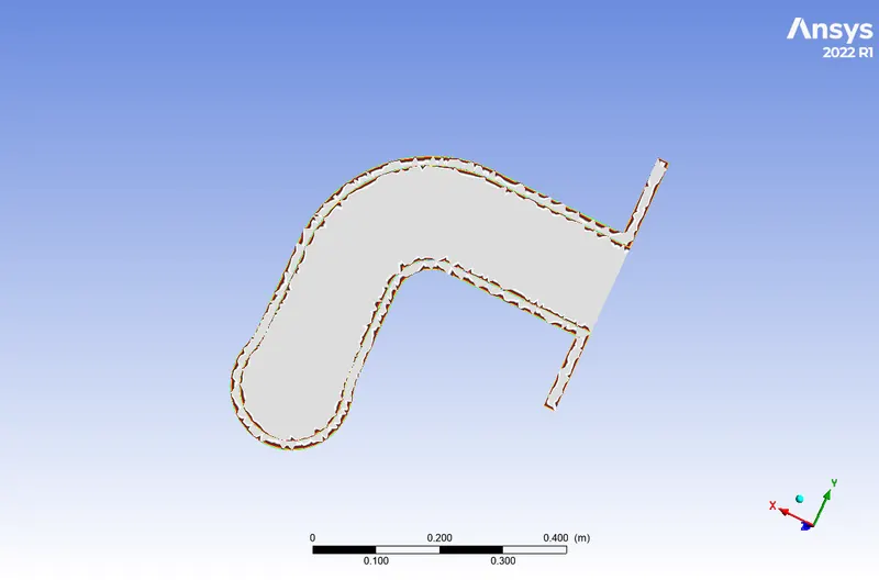
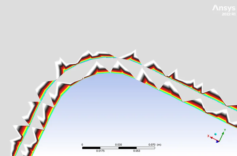
4.How would you verify if the HTC predictions from the simulations are right? On what factors does the accuracy of the prediction depend on?
Heat Transfer Conjugate Simulations are goverened by 'Dittus-Boelter Equation' which is an explicit function which is proportional to Reynolds No. and Prandtl No. and it is given by
`Nu = 0.023*Re^(4/5)*Pr^n`
- Nu = Nusselt No.
- Re = Reynolds No.
- Pr = Prandtl No.
- n = Heating Component = 0.4
Nusselt Number = Nusselt number is defined as the ratio of convection heat transfer to conduction heat transfer across a boundary in a fluid
Nu = hD/k
- h = Heat transfer coefficient
- D = Hydraulic Diameter
- k =Thermal Conductivity of Fluid i.e Air
Prandtl Number= It is defined as the ratio of momentum diffusivity to thermal diffusivity
Pr = µCp/k
- µ = Dynamic Viscosity
- Cp = Specific Heat Capacity
- k = Thermal Conductivity of Fluid i.e Air
- Now For 700 Kelvin( which is our temperature value for the simulation)
- Cp = 1.0750 Kj/Kg-K
- Pr = 0.684
- µ = 1.7894 E - 5 kg/m-s
- Reynolds Number = 56858.37
- Now putting the values in Dittus-Boelter Equation Nusselt No comes out to be 125.77
- Now Diameter = 0.16611 meters
- Thermal Conductivity = 0.025 W/mK
- From There The Value of Heat Transfer Coefficient comes out to be 18.93 W/(m^2 K)
- By comparing the heat transfer coefficient value from theoritical results and from the results obtained from CFD Simulations under +/- 5 % Tolerance limit we can validate our results