Perform Meshing Of Washer with Meshing Guidelines
Aim : To Perform Meshing Of Washer
Objective : To Perform Meshing of Washer applying zone cut and using meshing guidelines using dia = 1.5 to 2 for 1st case and dia = 1.75 to 2 for 2nd case
Geometry Preparation
- Import our Cad Geometry
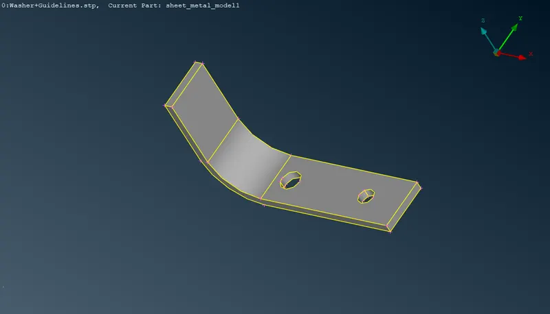
After importing the raw geometry, the first thing we should check are the units.
We can perform this step under Tools -> Settings -> Resolution/Tolerance/Units
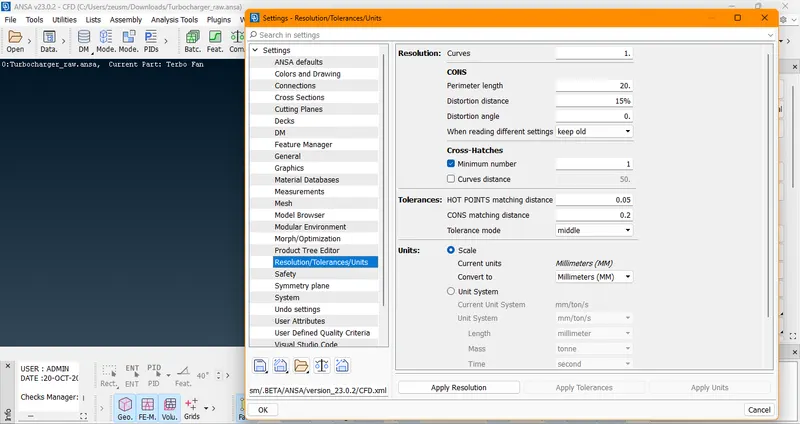
Then we should check for resolution (perimeter). If the raw geometry has distortion, it can be fixed by changing its perimeter.
We can perform this operation under Mesh -> Length -> Perimeter ->Select the whole geometry -> Length Parameters -> 1 mm
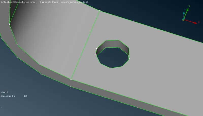
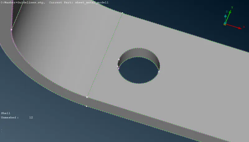
- Measure the Geometry Thickness
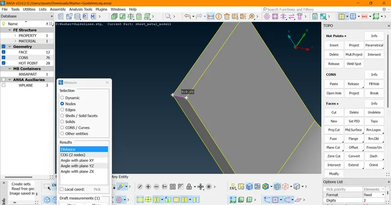
- Here the thickness is 8 mm which meant that we can go for 2d Meshing Operation
- For sheet metal operation the thickness is taken to be in between 3 mm to 8 mm
Mid Surface Extraction
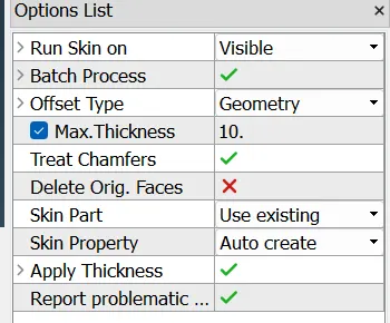
Faces -> Mid Surface -> Skin -> Select the Geometry -> Thickness -> 10mm( > 8 mm) -> Confirm Selection.
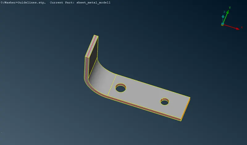
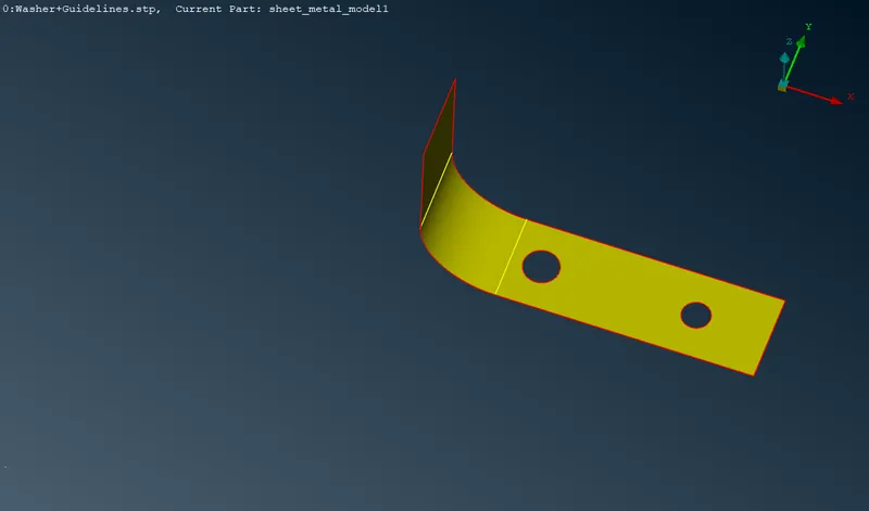
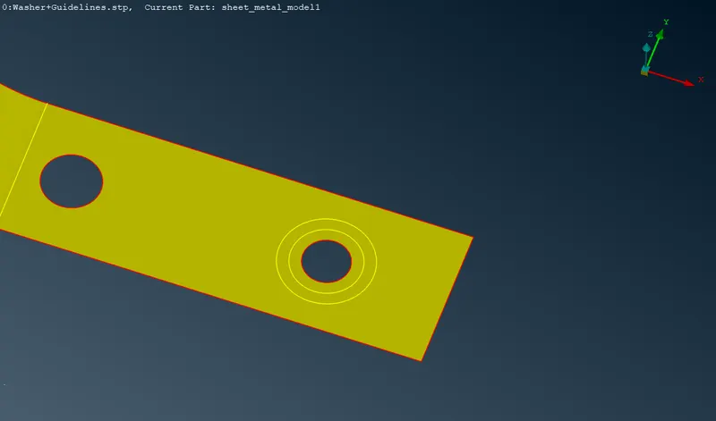
Now we need to put the washer in the holes..for that we need to zone cut operations
Zone Cut
For for calculating the First Washer Diameter = [ (1.5 D) - D ]/2 = (24-16)/2 = 4 mm
Diameter of the hole is = 16 mm
For for calculating the Second Washer Diameter = [ (2 D) - D ]/2 = (32-16)/2 = 8 mm
Diameter of the hole is = 16 mm
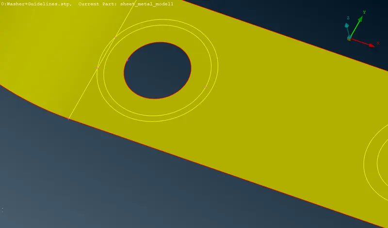
Similarly for the Second Washer
We need to take 1.75D and 2D Zone cut width is 6 mm and 8 mm
Meshing of the Geometry
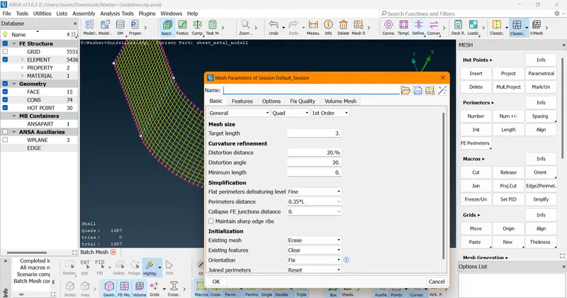
- Here, we will be using Batch Mesh Process for meshing
- We will be Quad Elements for the Meshing
- Target Length -> 3 mm
- Distortion Angle -> 20
- Distortion Distance -> 20
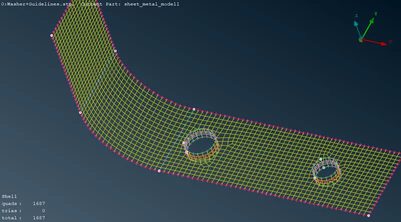
Final Output
Conclusion
- For sheetmetal components we should use element size between 3mm-8mm for relatively short parts.
- Distortion Angle and Distortion Distance of 20 helped us in removing the tria elements