Week 8 - Simulating Cyclone separator with Discrete Phase Modelling
Aim :- To perform analysis on cyclone separator and calculate the separation efficiency and pressure drop.
Objective :-
- To write a few words about any four empirical models used to calculate the cyclone separator efficiency.
- To perform an analysis on a given cyclone separator model by varying the particle diameter from 1 μm to 5 μm and calculate the separation efficiency in each case. Discuss the results. [Use both the velocity's as 3m/sec.]
- To perform an analysis on a given cyclone separator model by varying the particle velocity from 1 m/sec to 5 m/sec and calculate the separation efficiency and pressure drop in each case. Discuss the results. [Use particle diameter size as 5 μm for all cases & keep flow velocity same as particle velocity]
Theory :-
Cyclones Separators are devices that separate particles from carrier gas by using the centrifugal force created by a rotating gas stream. They are one of the most extensively used particle removal devices due to their simple design, low maintenance costs, and adaptability to a wide range of working circumstances, such as diameters and flow rates. They can be converted for use in difficult working circumstances such as high temperatures, high pressure, and corrosive gases by employing appropriate materials and building methods. They play a significant role in particle removal in both engineering and process operations.
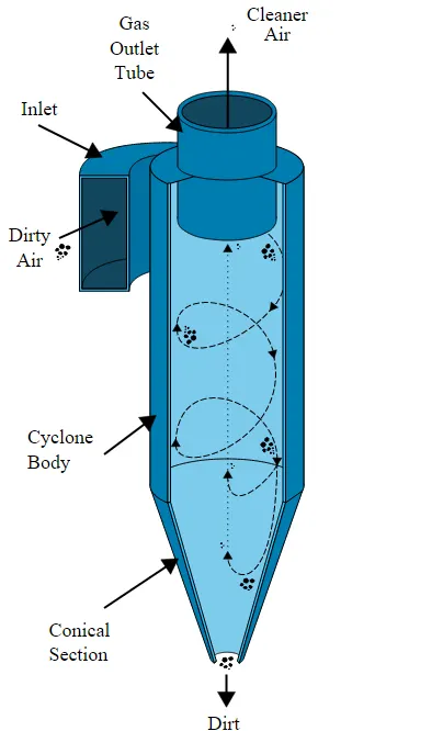
Working Principle Of Cyclone Separator
- The feed is introduced tangentially at very high velocity and acquires an intense vortex motion, which is moving downwards into the cylindrical chamber, also known as Barrel
- Due to this high centrifugal force,the heavier particles collides with the walls of the chamber and eventually it slides down to the bottom of the outlet
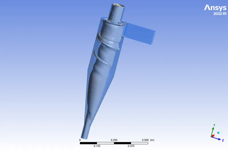
- The velocity of the stream increases as it reaches the conical base region due to the decrease in area which results in increase of centrifugal forces which in turn creates a low pression region along the axis of the cyclone separator, then the stream(clean air) carrying finer particles with them comes out from the top outlet and the denser particles(dirt) collide with the walls and eventually comes out from the bottom outlet.
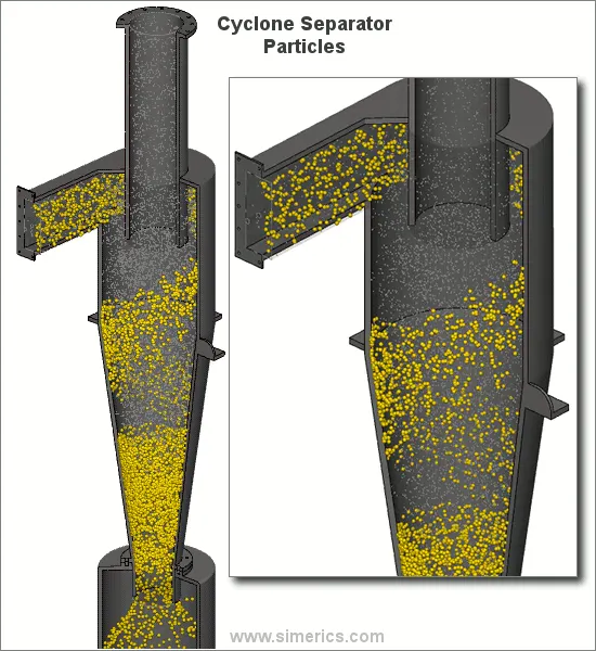
- To write a few words about any four empirical models used to calculate the cyclone separator efficiency.
The four empirical models used to calculate the cyclone separator efficiency are as follows
IOZIA AND LEITH MODEL
- It is a modified version of the Barth Model, which was created using force balance
- The IOZIA AND LEITH MODEL implies that a particle carried by a vortex is subject to two forces: centrifugal force Z, and flow resistance, W
- The core length, zc, and core diameter, dc are specified as follows:
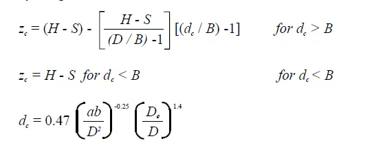
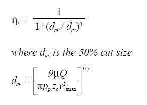
- Iozia and Leith's additions to the original Barth model are the core length zc and slope parameter expression, which are derived from statistical analysis of experimental data from a cyclone with D = 0.25 m. From the particle diameter, the collection efficiency( ηi) may be derived using the following expression shown below
LI AND WANG MODEL
- It comprises turbulent diffusion at the cyclone wall and particle bounce or re-entrainment.
- It is possible to express the particle distribution in the cyclone analytically in two dimensions.
- The following presumptions served as the foundation for the Li and Wang model:
- For uncollected particles inside the cyclones, the radial particle velocity and the radial concentration profile are not constant.
- The following are the boundary conditions when the turbulent diffusion coefficient and particle bounce re-entrainment on the cyclone wall are taken into account:
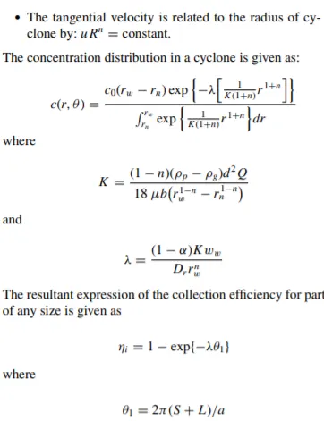
Koch and Licht Model
- The theory recognized the inherently turbulent nature of cyclones and the distribution of gas residence times within the cyclone.
- Koch and Licht describe particle motion in the entry and collection regions with the additional following assumptions:
- The tangential velocity of a particle is equal to the tangential velocity of the gas flow, i.e. there is no slip in the tangential direction between the particle and the gas.
- The tangential velocity is related to the radius of cyclone by: `uR^n.`= constant.
- A force balance and an equation on the particles collection yields the grade efficiency ηi.
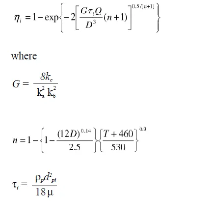
- G is a factor related to the configuration of the cyclone, n is related to the vortex and τ is the relaxation term.
LAPPLE MODEL
- It was created based on force balance without taking into account flow resistance.
- Lapple believed that a particle entering the cyclone is spread uniformly throughout the input aperture.
- The particle that passes from the input half width to the cyclone wall is captured with 50% efficiency.
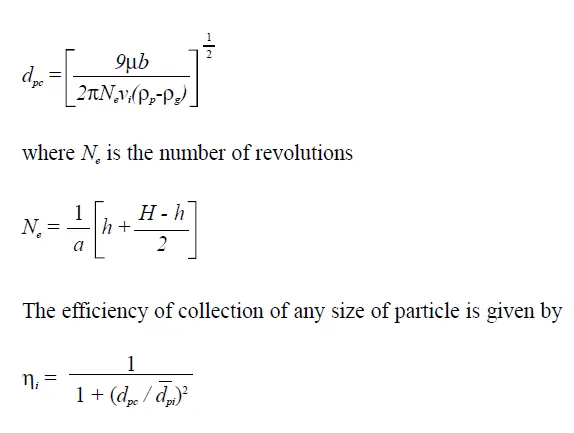
- The semi-empirical relationship for calculating a 50% cut diameter, dpc, is as follows:
Geometry Preparation
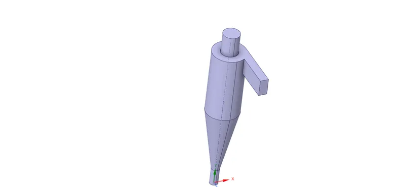
- Importing our Geometry in Spaceclaim.
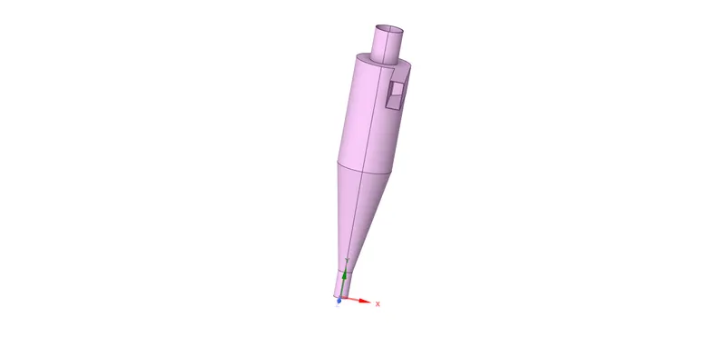
- Fluid Volume Extraction
Meshing The Geometry
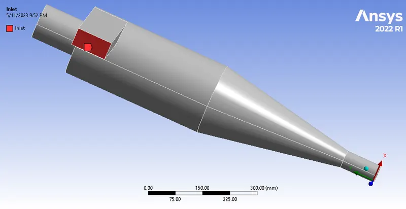
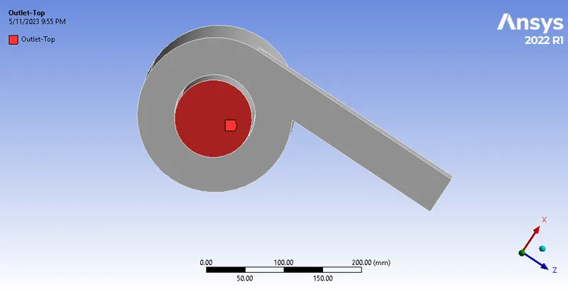
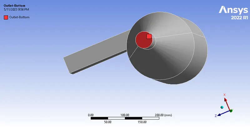
Named Selection
Inlet
Outlet-Top
Outlet-Bottom
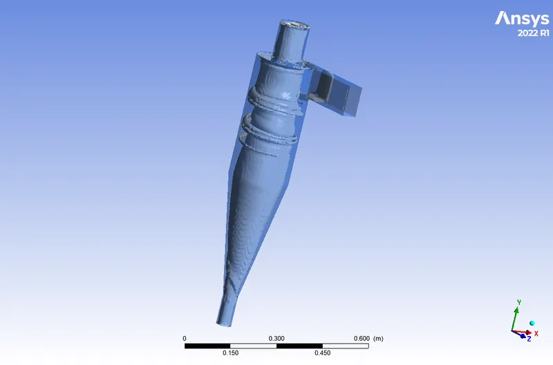
Meshed Geometry
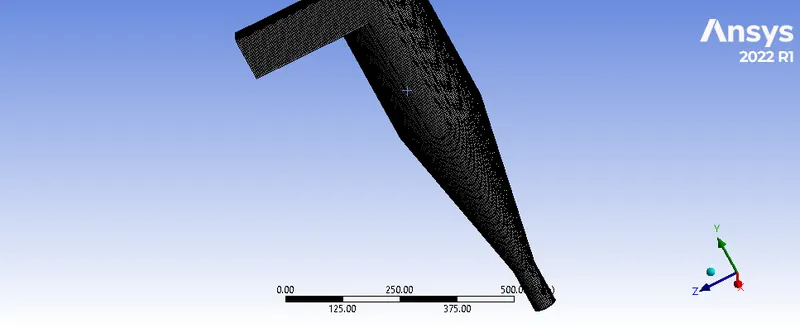
Mesh Metrics

Mesh Counts

Setup
- Solver Type : Pressure Based
- Solver Time : Steady State
- Gravity : -9.81 m/s^2
- Turbulence Model : K-Epsilon -> RNG (used to enhance the accuracy of swirling flows) -> Swirl-Dominated-Flow
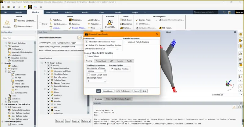
- Discrete Phase Model
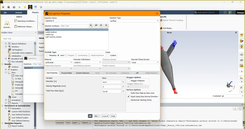
- Injection Properties
- Boundary Conditions
- Inlet -> 3 m/s -> DPM -> Discrete Phase BC Type -> Reflect
- Wall -> DPM -> Discrete Phase BC Type -> Reflect
- Outlet-Top -> DPM -> Discrete Phase BC Type -> Escape
- Outlet-Bottom -> DPM -> Discrete Phase BC Type -> Trap
- Solution Methods -> Momentum -> Second Order Upwind -> Turbulent Dissipation Rate -> Second Order Upwind (because second order upwind will provide better results for such simulation)
- Initialization -> Standard Initialization -> Compute From Inlet
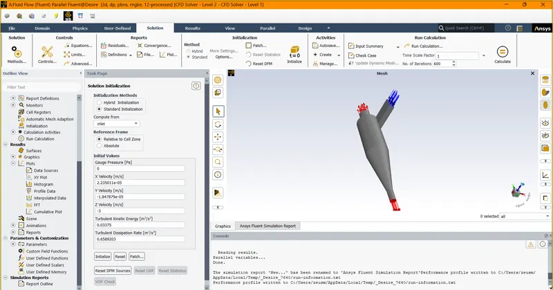
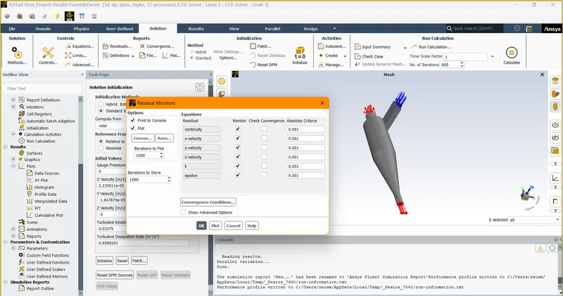
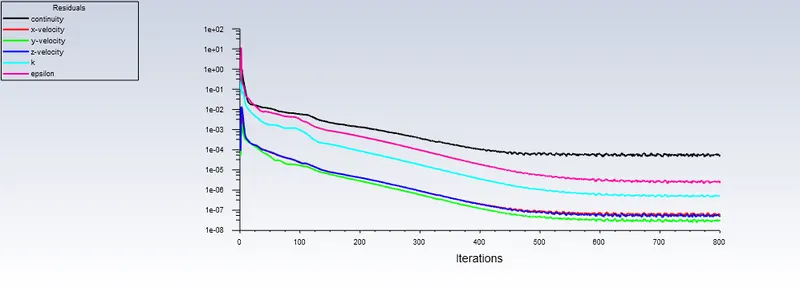
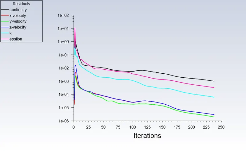
- Residuals -> Convergence Criteria -> Unchecked -> To capture the physics behind the simulation
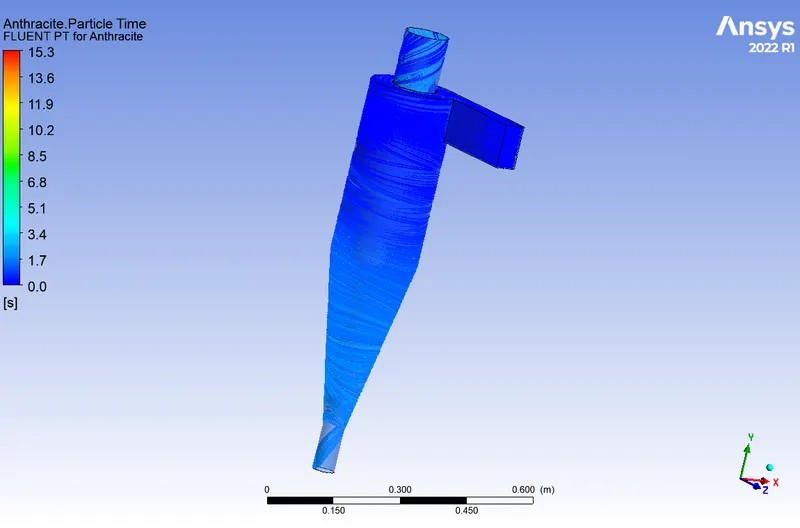
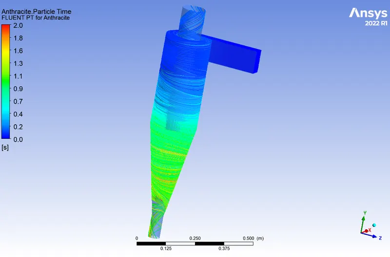
- It will be useful in keeping track of incomplete particles.
Post Processing Results
2. To perform an analysis on a given cyclone separator model by varying the particle diameter from 1 μm to 5 μm and calculate the separation efficiency in each case. Discuss the results. [Use both the velocity's as 3m/sec.]
Case 1 Diameter = 1 μm and Velocity = 3 m/sec
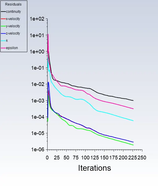
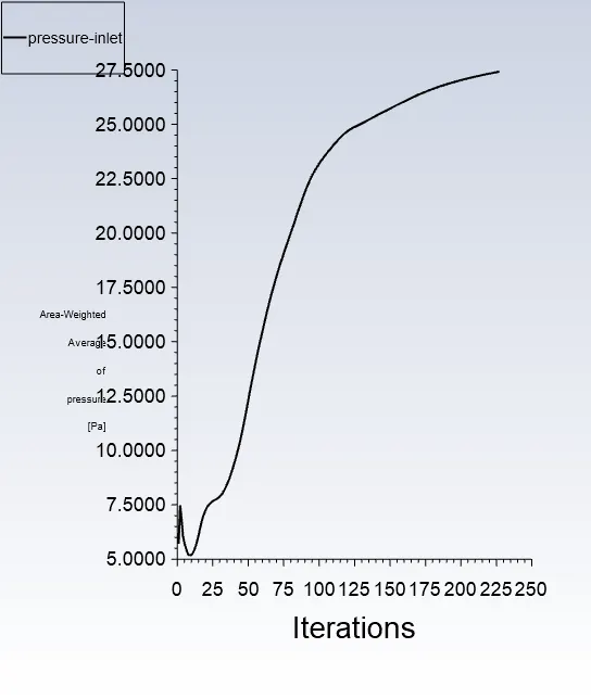
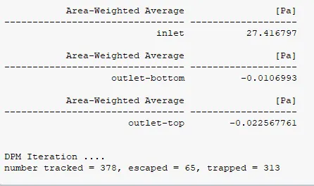
- Seperation Efficiency = No: of particles trapped/No: of particles tracked = (313/378)x100=82.80%
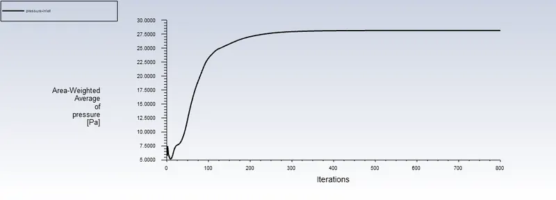
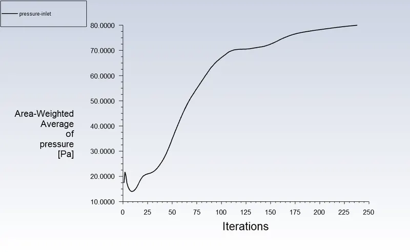
- Pressure drop = Inlet pressure - Total outlet pressure
= 27.416797 - (-0.0225677+(-0.0106993)) = 27.384 Pa
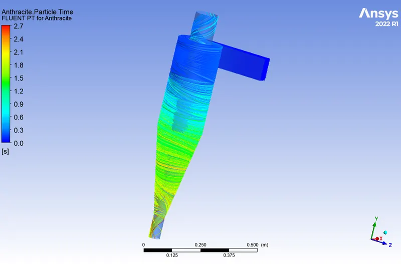
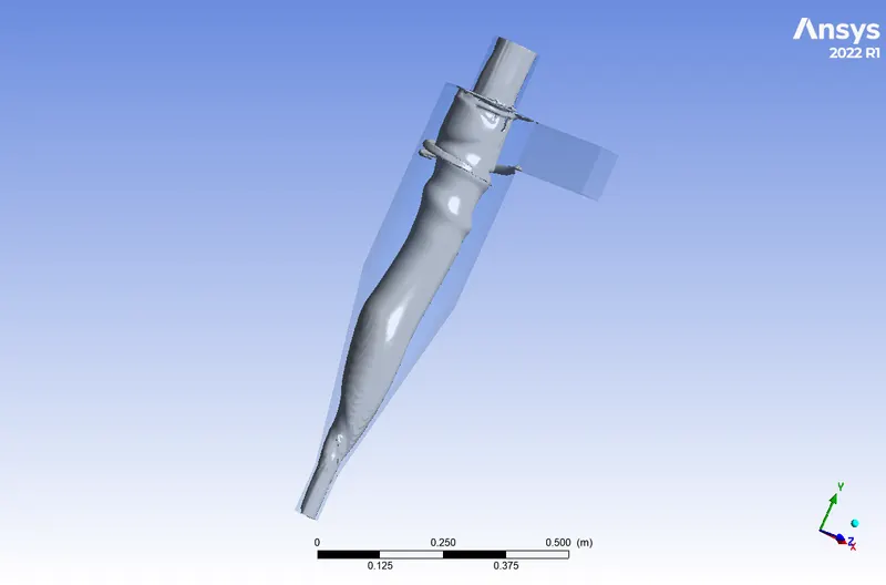
Case 2 Diameter = 3 μm and Velocity = 3 m/sec
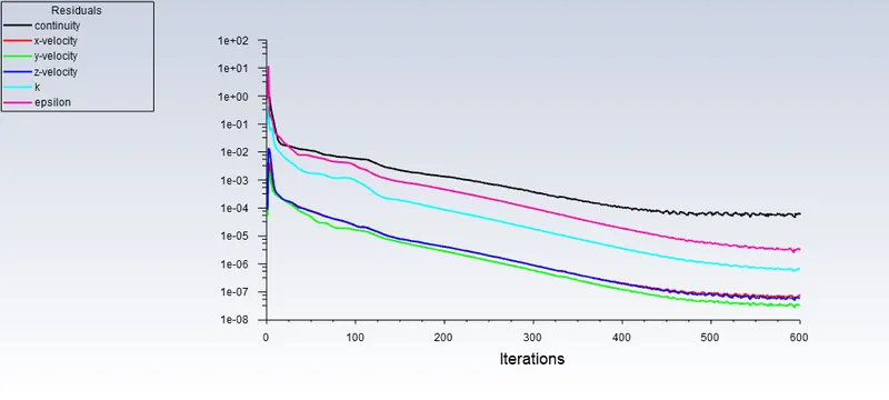
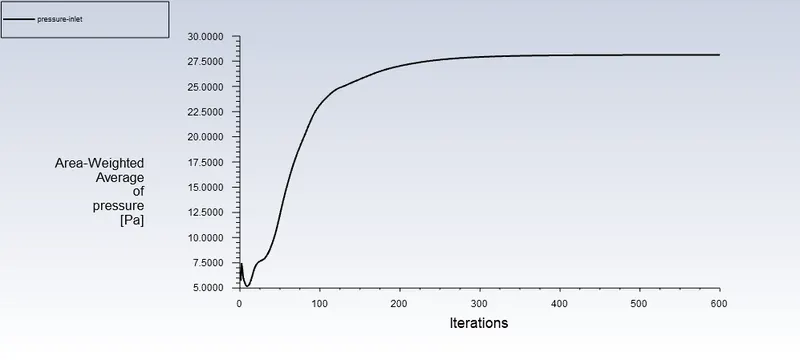
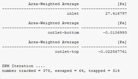
- Seperation Efficiency = No: of particles trapped/No: of particles tracked = (314/378)x100=83.07%
- Pressure drop = Inlet pressure - Total outlet pressure
= 27.416797 -(-0.0225677 +(-0.0106993) = 27.384 Pa
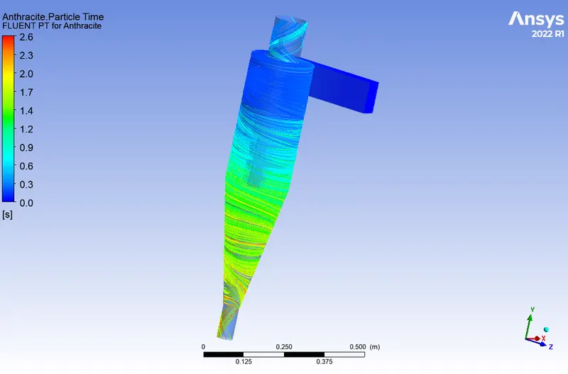
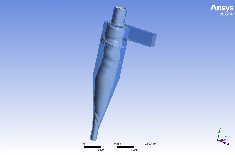
Case 3 Diameter = 5 μm and Velocity = 3 m/sec
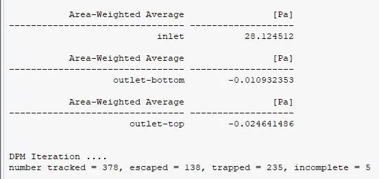
- Seperation Efficiency = No: of particles trapped/No: of particles tracked = (235/378)x100=62.17%
- Pressure drop = Inlet pressure - Total outlet pressure
= 28.124512 - (-0.00246414+(-0.0109325) = 28.09 Pa
3. To perform an analysis on a given cyclone separator model by varying the particle velocity from 1 m/sec to 5 m/sec and calculate the separation efficiency and pressure drop in each case. Discuss the results. [Use particle diameter size as 5 μm for all cases & keep flow velocity same as particle velocity]
Case 1 Velocity = 1 m/s and Diameter = 5 μm
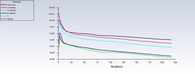
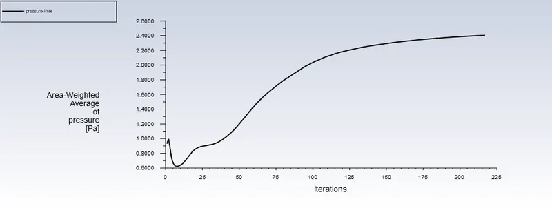
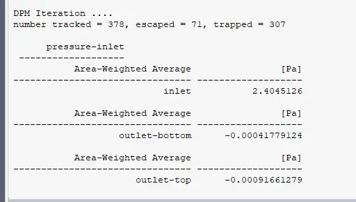
- Seperation Efficiency = No: of particles trapped/No: of particles tracked = (307/378)x100 = 81.21%
- Pressure drop = Inlet pressure - Total outlet pressure
2.40 -(-0.0009166+(-0.0004177)) = 2.3987 Pa
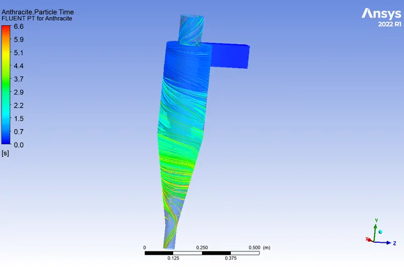
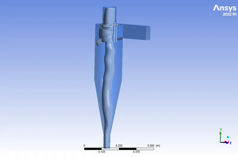
Case 2 Velocity = 3 m/s and Diameter = 5 μm
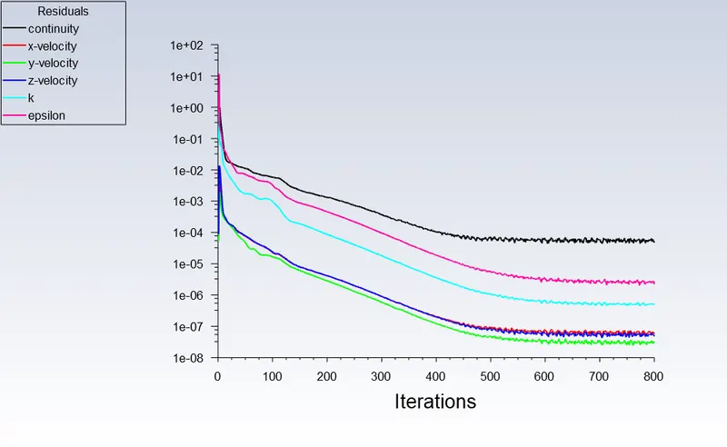
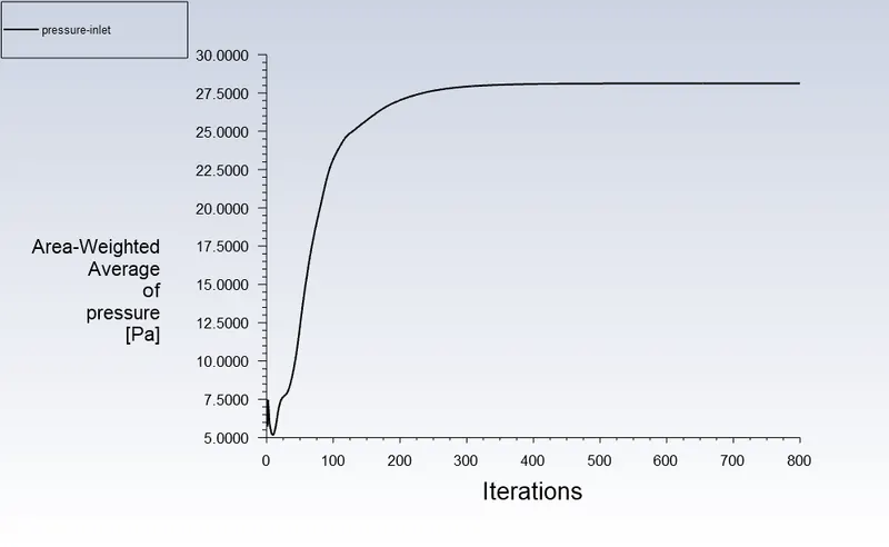
- Seperation Efficiency = No: of particles trapped/No: of particles tracked = (235/378)x100 = 62.17 %
- Pressure drop = Inlet pressure - Total outlet pressure
28.124512 - (-0.0246414 + (-0.0109323)) = 28.089 Pa
Case 3 Velocity = 5 m/s and Diameter = 5 μm
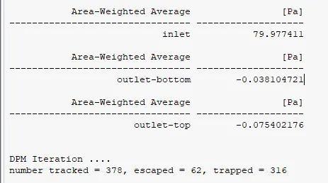
- Seperation Efficiency = No: of particles trapped/No: of particles tracked = (316/378)x100 = 83.60%
- Pressure drop = Inlet pressure - Total outlet pressure
79.977411-(-0.0754021+(-0.0381047)) = 79.864 Pa
Results
| Diameter(µm) | Velocity(m/s) | Particles Tracked | Particles Trapped | Particles Escaped | Particles Incomplete | Separation
Efficiency
|
Pressure Drop(Pa) |
| 1e-6 | 3 | 378 | 313 | 65 | 0 | 82.80 | 27.384 |
| 3e-6 | 3 | 378 | 314 | 64 | 0 | 83.07 | 27.384 |
| 5e-6 | 3 | 378 | 235 | 138 | 5 | 62.17 | 28.09 |
| Diameter(µm) | Velocity(m/s) | Particles Tracked | Particles Trapped | Particles Escaped | Particles Incomplete | Separation Efficiency | Pressure Drop (Pa) |
| 5e-6 | 1 | 378 | 307 | 71 | 0 | 81.21 | 2.3987 |
| 5e-6 | 3 | 378 | 235 | 138 | 5 | 62.17 | 28.09 |
| 5e-6 | 5 | 378 | 316 | 62 | 0 | 83.60 | 79.864 |
Conclusion
- The pressure drop is solely determined by the particulate's velocity. As velocity increases, so does the pressure difference between inlet and output pressure increases.
- The cyclone separator simulation is supposed to have no incomplete particles. However, one of the cases presented above has incomplete particles due to computational limitations.
- The efficiency of the cyclone separator is proportional to the particulate flow velocity. In a nutshell, increased velocity yields higher efficiency.