Week 3 - External flow simulation over an Ahmed body.
Aim : To perform External flow simulation over an Ahmed body
Objective : To perform External flow simulation over an Ahmed body for the velocity of 25 m/sec with the default air properties in fluent.
Q1. Describe Ahmed's body and its importance
Introduction of Ahmed Body
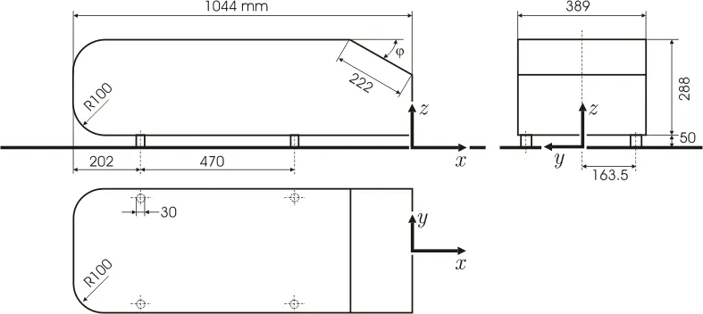
Ahmed Body is a bluff body( a generic car body) proposed by S. R. Ahmed, G. Ramm and G. Faltin in the year 1984. Ahmed body is a simplified car body used in many automotive industry to study the influence of flow structure on the drag.The airflow around the Ahmed Body helps us to capture the essential flow feature around automobile. It also allow us to capture the characteristic features that are relevant to bodies in automobile industry. Dimensions of Ahmed Body are as follows
Importance Of Ahmed Body
One of the major issues for the transport sector is to reduce fuel usage and emissions. Depending on the vehicle type and road conditions, aerodynamic drag can account for 30 to 80% of total resistance for a vehicle travelling at highway speeds. As a result, aerodynamic drag has a significant impact on energy consumption and emissions. However, the flow around a vehicle affects not only the vehicle's performance, but also its safety and comfort.
The vehicle's rear end contributes significantly to drag. The bluff body has the potential to record similar flow behaviour around a vehicle, allowing more generalised shapes to be used to analyse flow characteristics. As a result, bluff bodies have been and continue to be frequently used in computational fluid dynamics (CFD) studies.
The Ahmed body is one of the most researched bluff bodies. This bluff body has a rounded front, a long midsection, and a box-shaped rear end with a top tilt; it was originally supported from the ground by four circular cylinders, one in each corner. The body was designed to highlight the effect on time-averaged wake patterns and how it affects the drag of such a fundamental vehicle type.
Because these vortical structures are immediately affected by the slant angle, the majority of the drag was caused by the low-pressure distribution at the slant and base of the body.
For slant angles less than 30°, a separating shear layer turns upwards from the slant's sides (C-pillar) and rolls into two longitudinal vortices, which dominate the wake's activity.
For slant angles close to 30°, the size of this separation grows, resulting in a low pressure near the slant's centre.
When the slant angle exceeds 30°, the flow divides and joins the C-pillar vortices, creating a big wake behind the body and reducing drag.
Q2. Explain the reason for the negative pressure in the wake region.
The flow behind an object separates from the surface, forming a highly turbulent zone known as the wake. As the flow separates, the pressure inside the wake zone remains low, producing a net pressure force (pressure drag). In other words, the pressure in the wake zone is low due to the formation of pressure drag caused by flow separation.
One of the major elements influencing flow is the pressure gradient. It is clear that shear stress induced by viscosity slows the flow. This impact can be mitigated by providing the flow with a negative pressure gradient. A beneficial pressure gradient is one that is negative. The flow is made possible by such a gradient. A positive pressure gradient has the opposite effect and is defined as adverse pressure gradient.
Q3. Explain the significance of the point of separation.
At the front, there is a slow moving air which provides laminar attached flow and as the air moves across the surface, the flow will stick with the surface locally and create a boundary layer of moving air. This boundary layer grows thicker and thicker as it moves across the surface and as soon air has passed over the mid-surface it needs to contract to get close to the wake region and it becomes difficult for the air to do so and at some point it will get detach(separate) from the surface and this detach(separated) flow creates a large wake behind the surface and it increases the drag.
The separation point is defined as the point where the air stops "sticking" to the object that is under the influence of the moving air
The boundary layer equations are no longer applicable when a boundary layer separates.However, we can predict the point of separation where the velocity gradient( or the shear stress) results to zero
Geometry Preparation :
- Import our Geometry in SpaceClaim
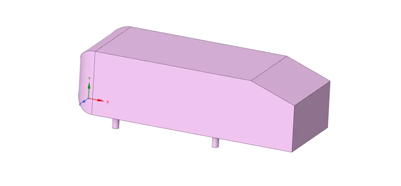
Creating The Enclosure
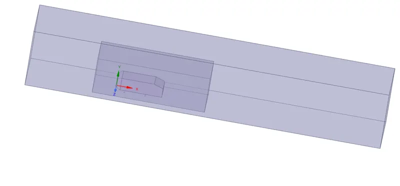
Splitting the Geometry
Create a plane along perpendicular axis of the geometry
Design -> Create Plane -> Choose Perpendicular Axis
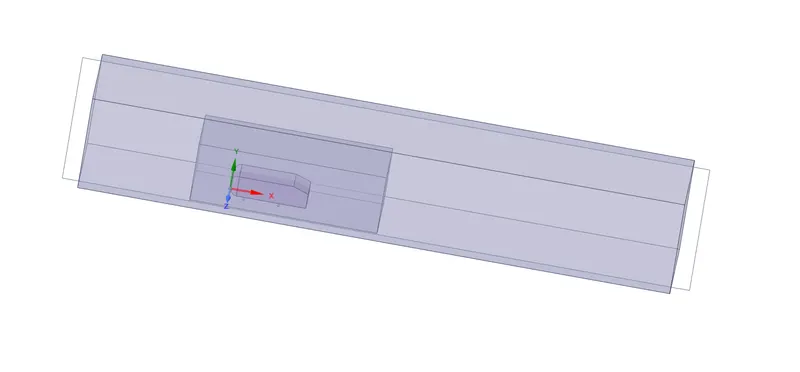
Splitting of the body
Design -> Split Body -> Select the body -> Choose the cutting plane -> Select the body to split
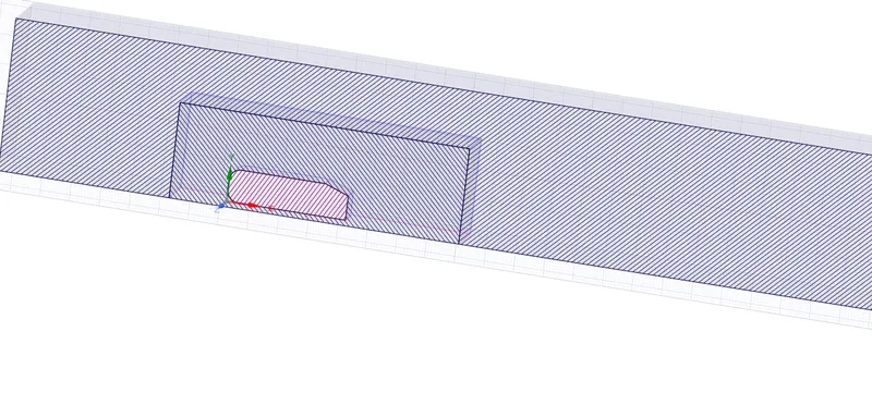
Check For Interference
Prepare -> Interference -> Select the geometry -> Confirm Selection to fix the issue
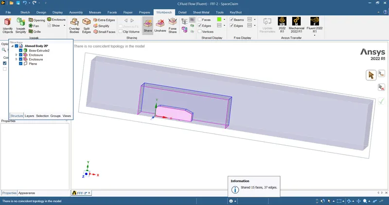
Sharing the Toplogy
Workbench -> Share -> Confirm selection to fix the issues
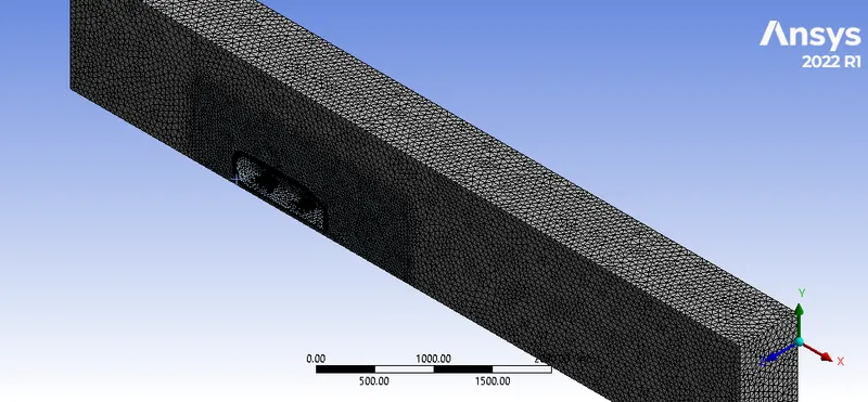
Meshing The Geometry
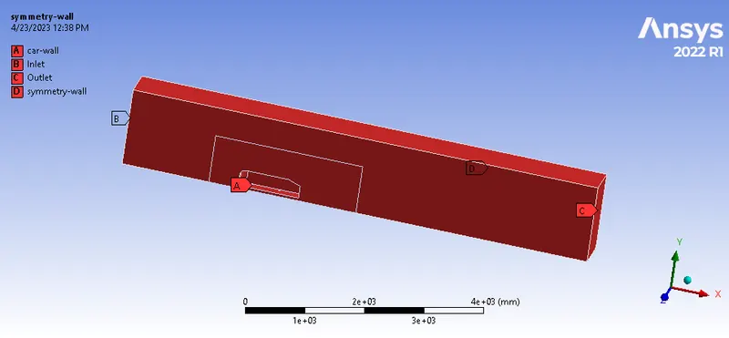
- Named Selection
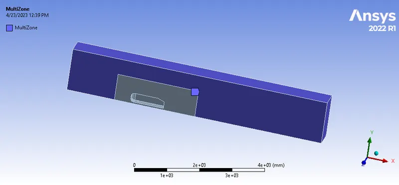
- Providing Multizone
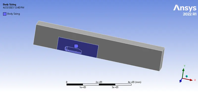
- Providing Body Sizing
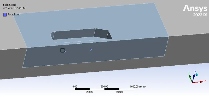
- Providing Face Sizing
- Patch Conforming Method
- Method -> Tetrahedron
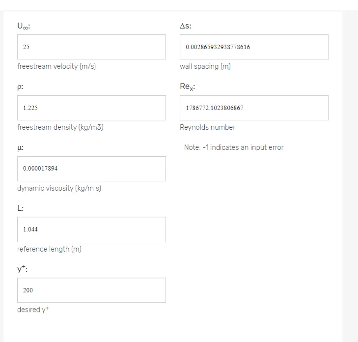
- First Layer Height Calculation
- Velocity = 25 m/s
- Length = 1.044 meters
- y+ = 200 ( 30 < y+ 300 )
- Free Stream Density and Dynamic Viscosity are from Air Properties
- First Layer Height = 0.0028659 meters
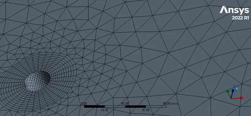
Creating Inflation Layers
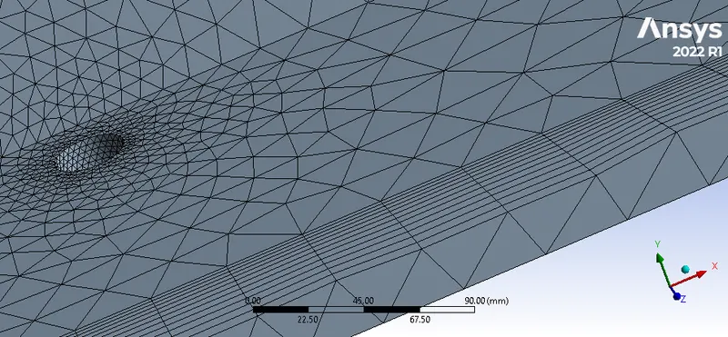
Final Geometry After Meshing
Setup
- Solver Type -> Pressure Based Solver
- Solver Time -> Steady State
- Turbulence Model -> K-Omega-SST
- Material -> Fluid -> Air
- Boundary Conditions
- Inlet Velocity -> 25 m/s
- Outlet -> Pressure Outlet
- Car Wall -> Wall Boundary Condition
- Side Faces of Enclosure -> Symmetry Boundary Condition
- Solving Method -> Coupled
Reference Values
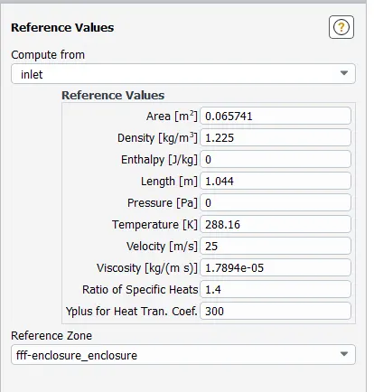
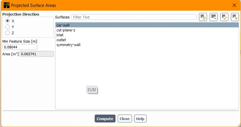
Area Calculation
- Length -> Length of the object
- Density & Viscosity -> Properties of Fluid
- Velocity -> Inlet Velocity
Post-Processing Results
Velocity Contour
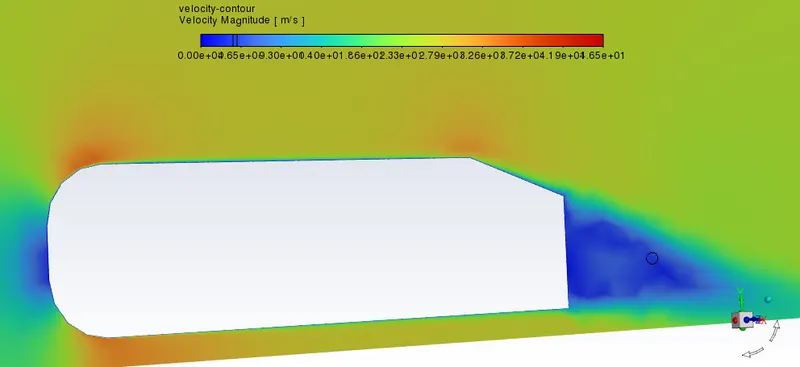
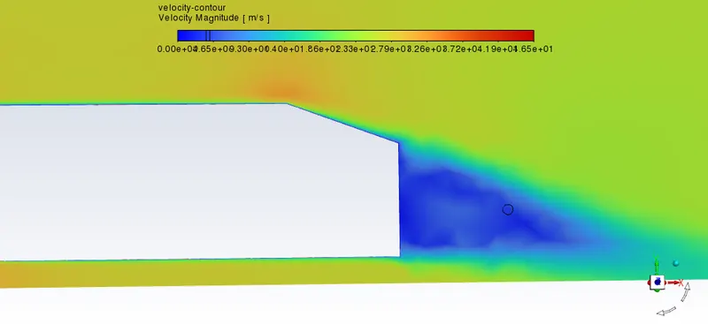
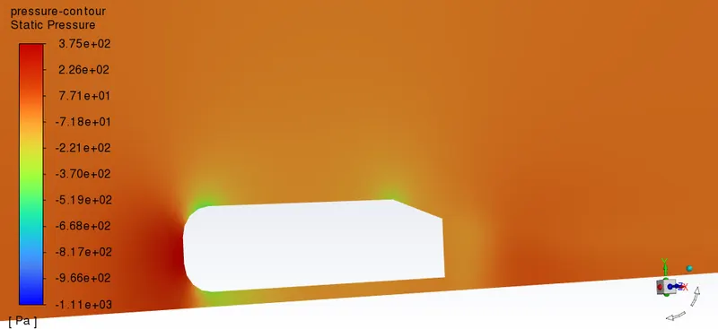
Pressure Contour
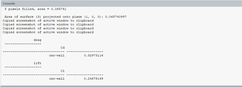
Drag & Lift Values
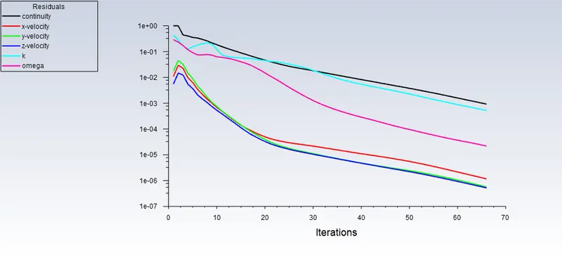
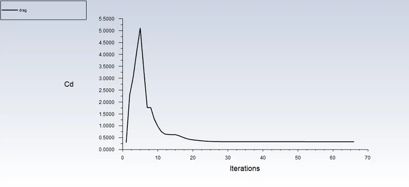
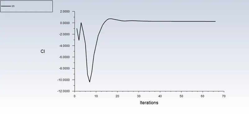
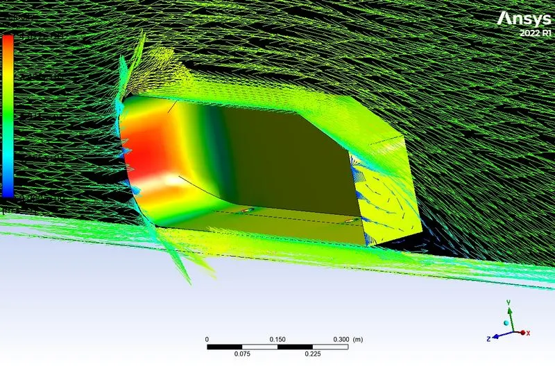
Vector Plots
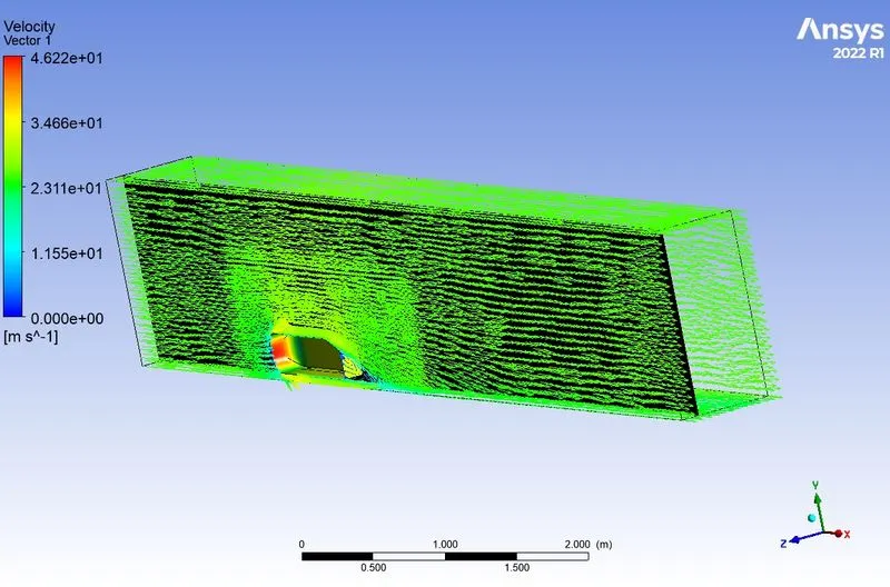
Mesh Independent Study
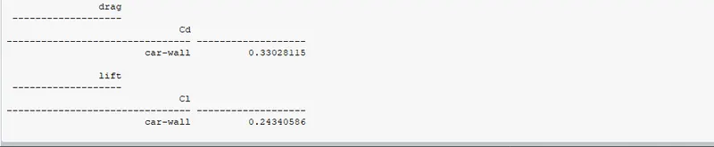
Fine Mesh


Drag & Lift Values

Finer Mesh

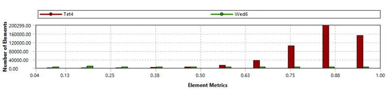
Drag & Lift Values
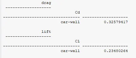
Finest Mesh


Drag & Lift Values
Grid Independency Test
| Mesh Type | Nodes | Elements | Drag Value | Lift Value |
| Fine Mesh | 85155 | 389877 | 0.330 | 0.242 |
| Finer Mesh | 113730 | 546276 | 0.330 | 0.243 |
| Finest Mesh | 318238 | 1681842 | 0.325 | 0.234 |
Conclusions
- The Bluff Car Body is axi-symmetric and it allows us to run the simulation considering one half of the body.
- The Ahmed Body is a well known CFD Benchmark for performing External Aerodynamics Simulations.