Week 9 - Parametric study on Gate valve.
Aim : To perform a parametric study on the gate valve simulation
Objective : To perform a parametric study on the gate valve simulation by setting the opening from 10 % to 80%.
- Obtain the mass flow rates at the outlet for each design point.
- Calculate the flow coefficient and flow factor for each opening and plot the graph.
- Discuss the results of the mass flow rate and flow coefficient.
Theory
- Gate valve (also known as a sluice valve), where the disc shape is in the shape of a gate or wedge-shaped.
It always opens in the perpendicular direction of the flow of the fluid.
It is only used to stop or restart the flow of the fluid.
It is unfit to use as a regulator because it creates a lot of noise and vibrations, which in turn cause leaking.
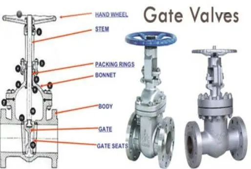
Working Principle Of Gate Valve
- A Gate Valve works in the same fashion as the other valves.
- To open the valve, turn the handwheel, which allows the gate valve to travel higher or lower on the stem via the threads.
- It requires more than a 360-degree spin to fully open or close the valve.
- When the gate is raised, an unhindered path for the fluid to flow is created.
- When the gate is lowered, the flow of fluid is restrained.
Geometry Preparation
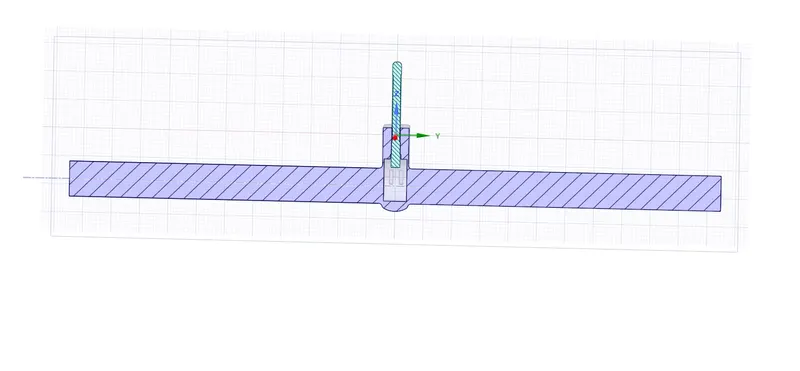
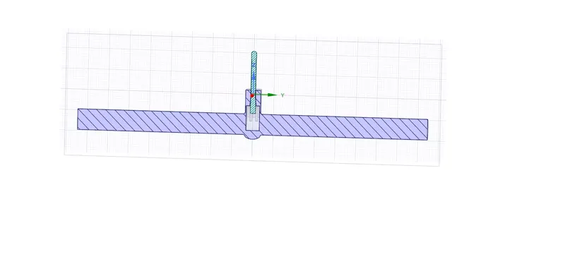
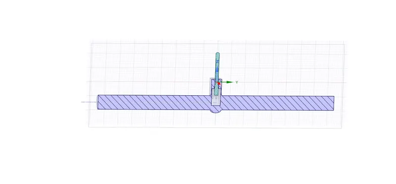
- Importing our Geometry in Spaceclaim.
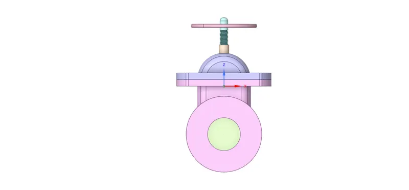
- Providing Initial Lift
- Hiding of the Bottom Part
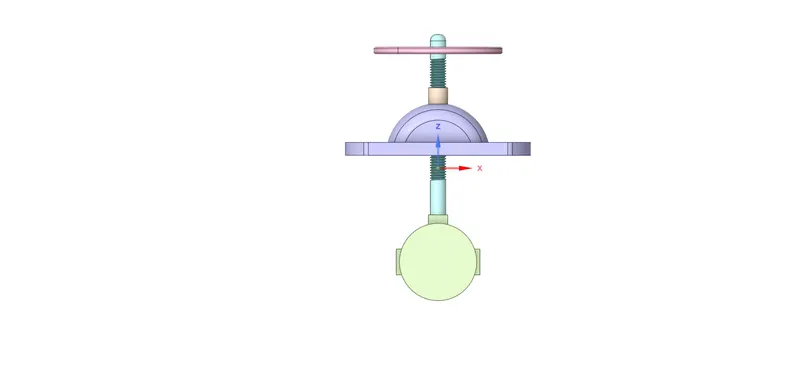
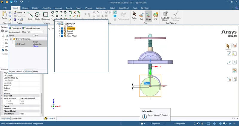
- Movement of the Gate Valve
- Move -> Select Component -> Select the Gate Valve -> Select the Z Axis -> Move it upwards for 10 mm
- Fluid Volume Extraction
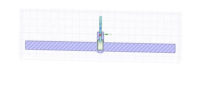
- Prepare -> Volume Extract -> Select Inlet and Outlet Edge -> Hide the Bonnet -> Select the third edge -> Confirm Selection
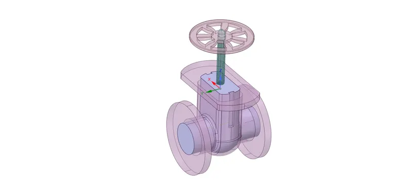
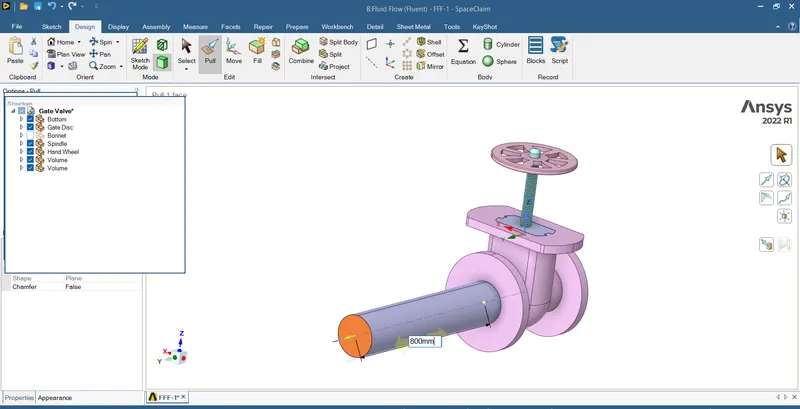
- Extend The Fluid Flow Region
Pull Tool -> Select The Edges -> Pull it for 800 mm
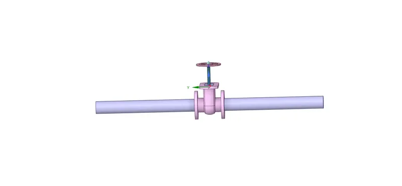
- Suppress The Solid Geometry For Physics
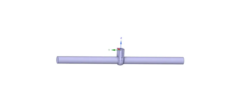
Meshing The Geometry
Named Selections
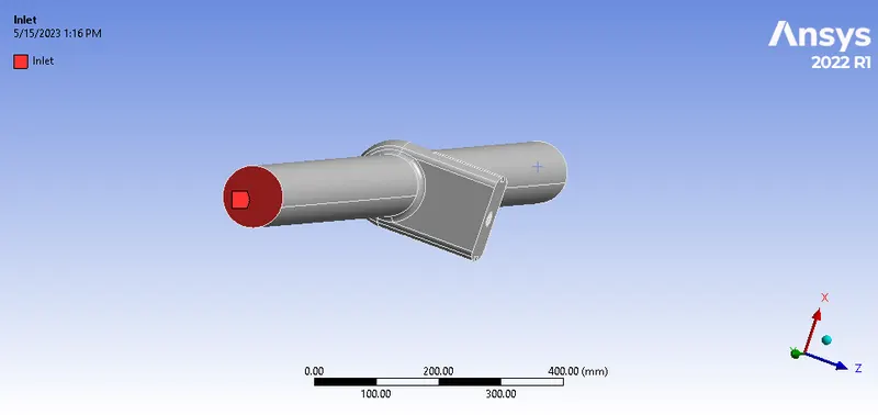
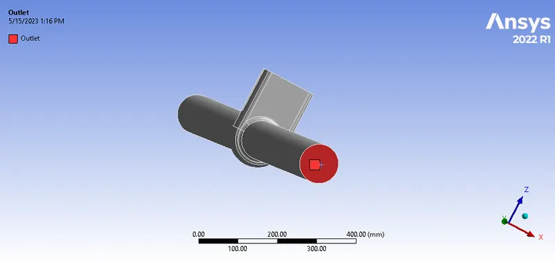
Meshed Geometry
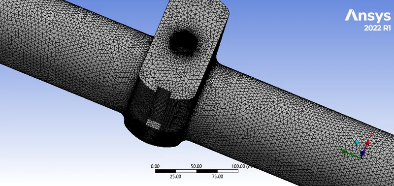
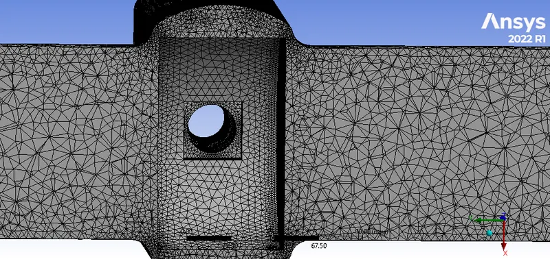
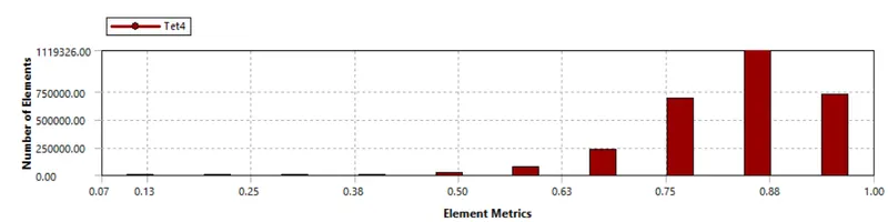
Mesh Metrics
Setup
- Solver Type : Pressure Based
- Solver Time : Steady State
- Gravity : -9.81 m/s^2
- Turbulence Model : K-Epsilon -> Realizable -> Scalable Wall Functions
- Material Selection -> Water-Liquid
- Cell Zone Conditions -> Change the default material to water-liquid
- Boundary Conditions
- Inlet -> Pressure-Inlet -> Total Gauge Pressure -> 10 Pa
- Outlet -> Pressure-Outlet
- Interior-Volume -> Interior
- Wall-Volume -> Wall
Calculations
- Reynolds No `Re = ρVD/μ`
- where as ρ = 998 kg/m^3
- Diameter = 0.1 m
- Velocity = 0.14145488 m/s
- Reynolds No. = 14087.14
- For pipe flow cases, the Reynolds number should be less than 2000 for the laminar region, as our value is exceeding the required value,so it is in the turbulent region.
Post Processing Results
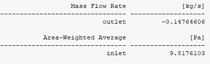
Case 1: Lift = 10 mm
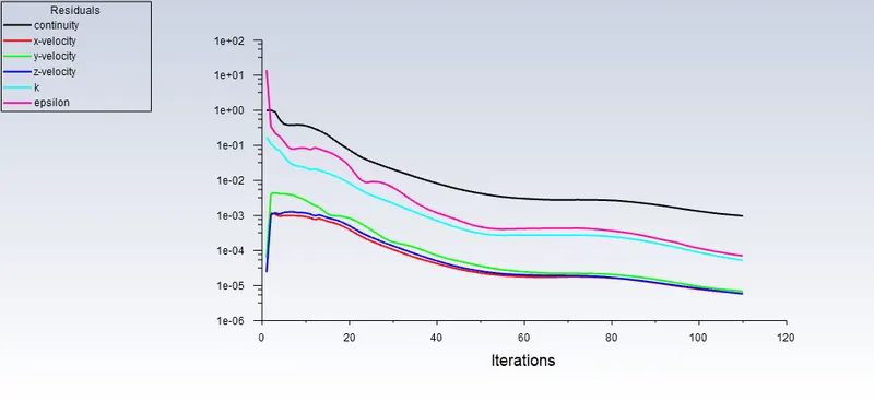
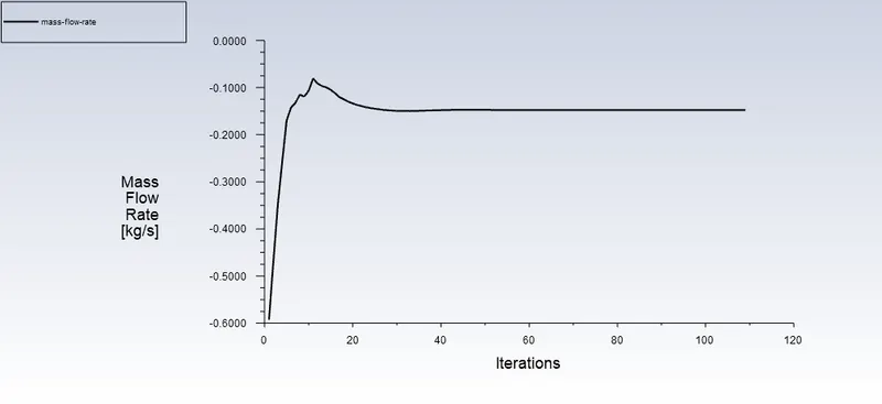
Case 2: Lift = 20 mm
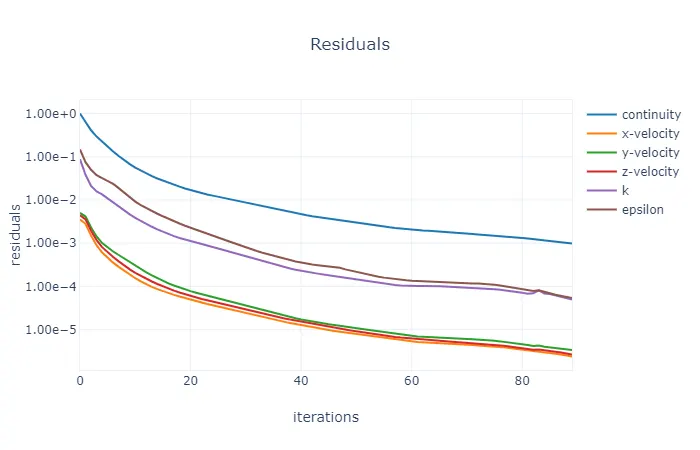
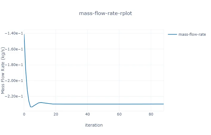
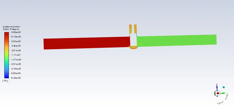
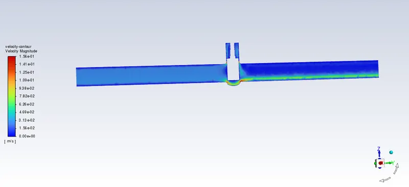
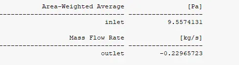
Case 3: Lift = 30 mm
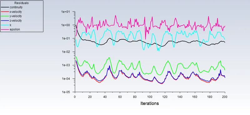
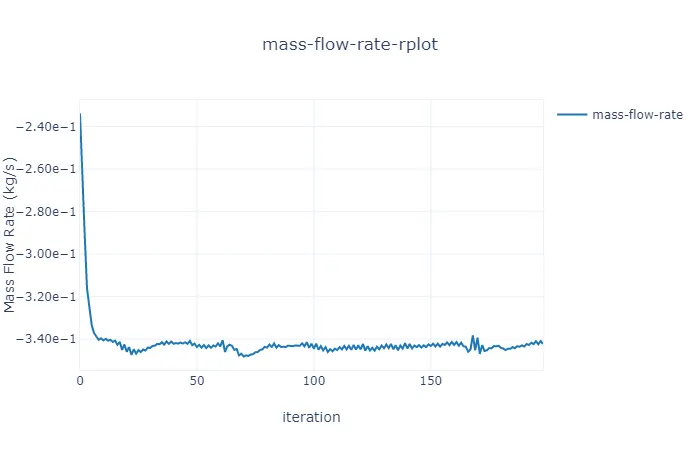
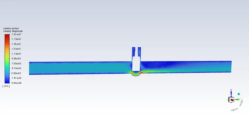
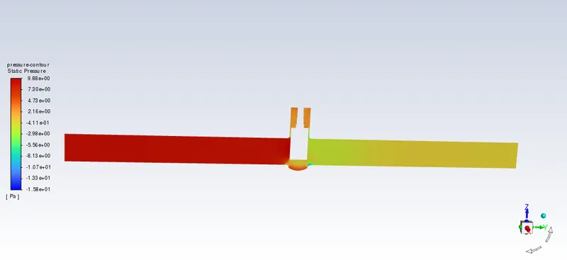
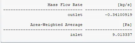
Case 4: Lift = 40 mm
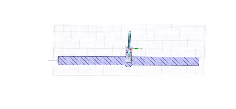
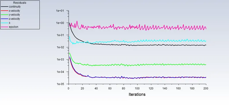
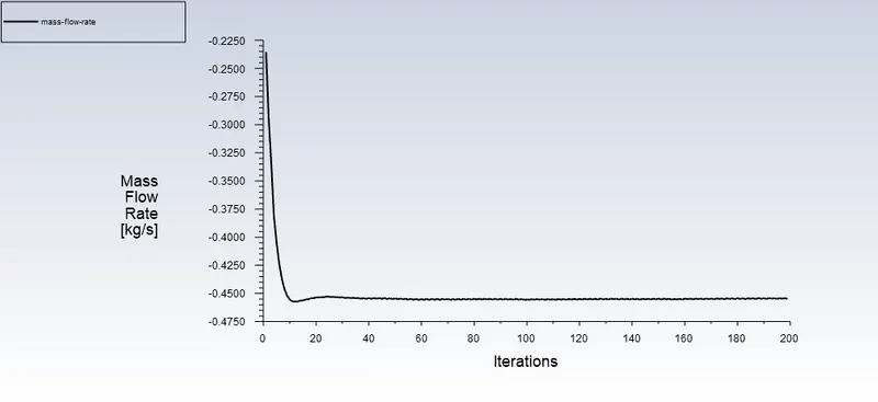
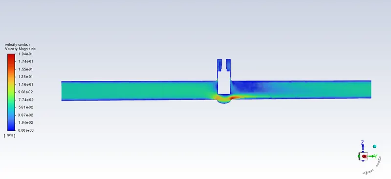
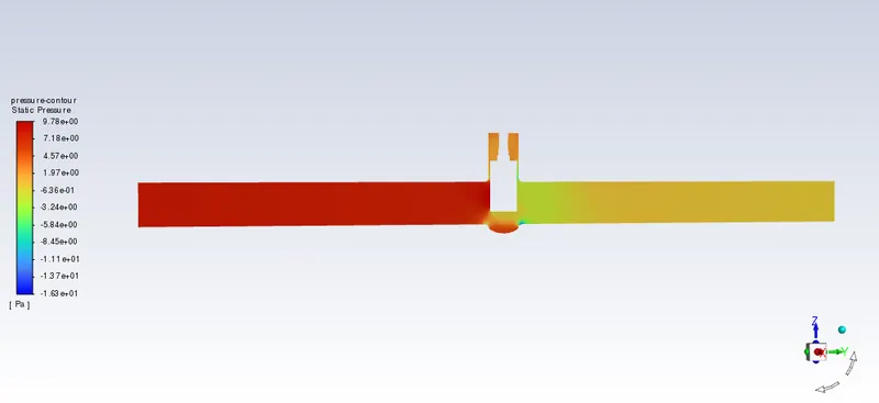
Case 5: Lift = 50 mm
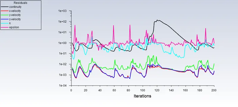
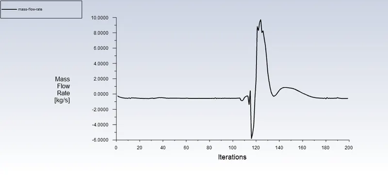
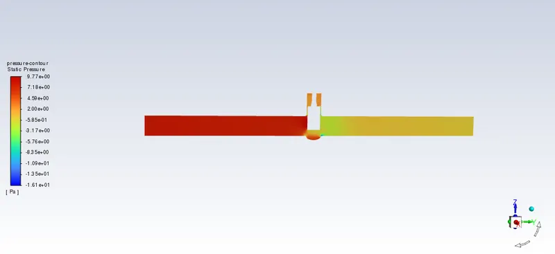
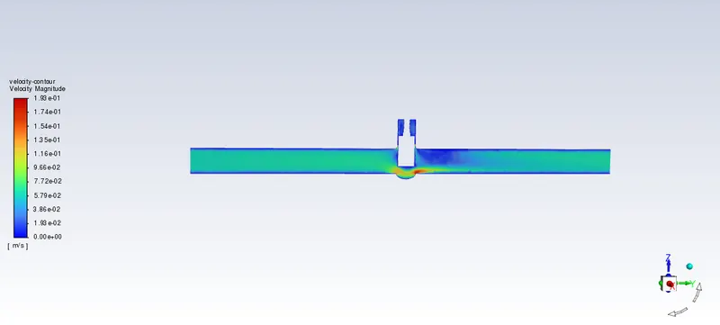
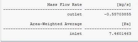
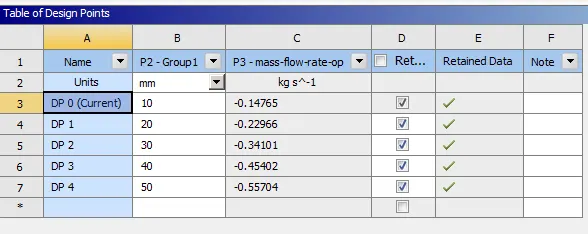
Results
- Flow Coefficient(Cv ) = Flow Factor(Kv) x 1.156
- whereas, Flow Factor(Kv) = Q x (Specific Gravity/Pressure Difference)^1/2
- where Q will be in m^3/hr
- Specific Gravity of Water = 1 gm/cc
- Pressure Difference = 100 Kpa
- 1 kg/s = 3.60 m^3/hr
Results Table
| Wedge Lift(mm) | Pressure Difference(Pa) | Mass Flow Rate (kg/s) | Volumetric Flow Rate(m^3/hr) | Flow Coefficient(Cv) | Flow Factor(Kv) |
| 10 | 10 | 0.14765 | 0.53154 | 53.15 | 61.4414 |
| 20 | 10 | 0.22966 | 0.826776 | 82.6776 | 95.575 |
| 30 | 10 | 0.36059 | 1.298124 | 129.8124 | 150.063 |
| 40 | 10 | 0.45402 | 1.634472 | 163.4472 | 188.9449 |
| 50 | 10 | 0.55704 | 2.005344 | 200.5344 | 231.8177 |
Graph
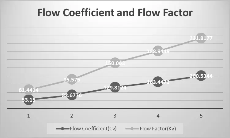
Conclusions
- The negative mass flow rate at the point of exit indicates that the fluid is leaving the system.
- The mass flow rate increases as the wedge's lift increases.
- The flow factor and flow coefficient are proprtional to each other.