Mid-surfacing and Meshing of Dashboard sub-part using ANSA
Mid-surfacing and Meshing of Dashboard sub-part using ANSA
Objective: For the given component, check for the geometrical errors and mesh with the given element Quality criteria. After meshing the component the thickness has to be assigned. Write a detailed report on your meshing process and also mention which method you used to extract the mid-surface along with the reason.
Quality Criteria:
|
S.No |
Quality Criteria |
Value |
|
1 |
Target/Average length |
4 |
|
2 |
Minimum Length |
2 |
|
3 |
Maximum Length |
6 |
|
4 |
Aspect |
3 |
|
5 |
Warpage |
15 |
|
6 |
Skewness |
45 |
|
7 |
Jacobian |
0.7 |
|
8 |
Minimum Quad Angle |
45 |
|
9 |
Maximum Quad Angle |
135 |
|
10 |
Minimum Tria Angle |
30 |
|
11 |
Maximum Tria Angle |
120 |
|
10 |
Tria Percentage |
15 |
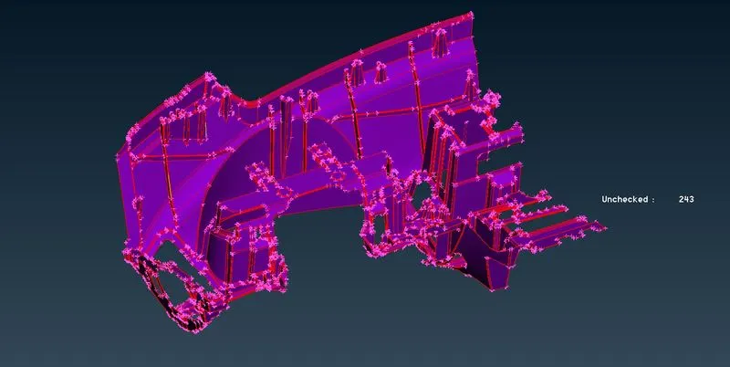
Model Setup: We performed ‘TOPO’ for the whole model to connect any unattached surface. The given model has been given with a single PID. Before proceeding with geometry check we give topo to connect all unstiched surfaces.
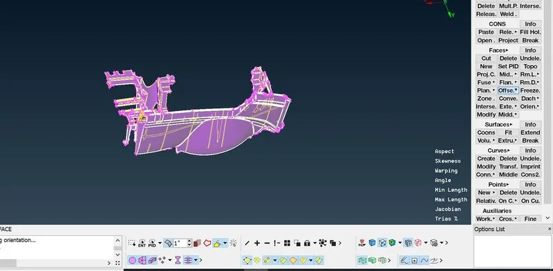
The given model is shown below.
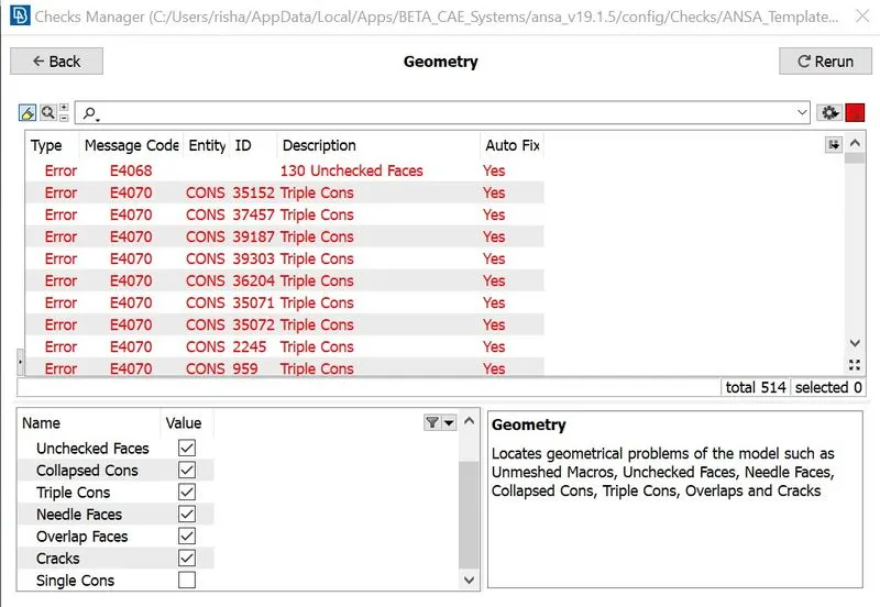
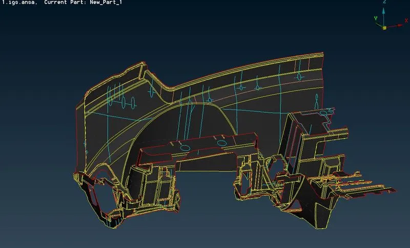
Geometry Check: From ‘Checks Manager’ using ‘Geometry’ we checked for any geometrical errors. And fixed using Auto Fix options. The below image shows the before and after results after removing all errors.
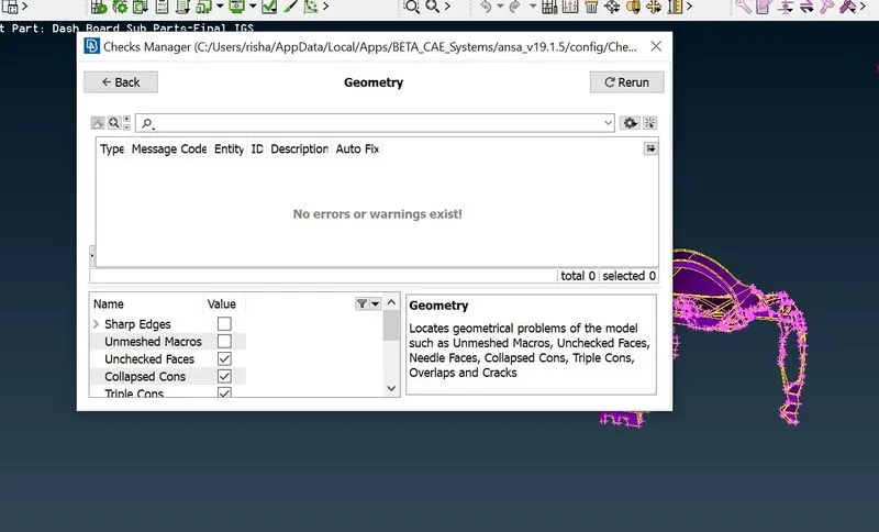
After removing all errors through Auto-fix and manual methods, geometery issues were resolved. Few surfaces required to be deleted and new srface was created in its place.
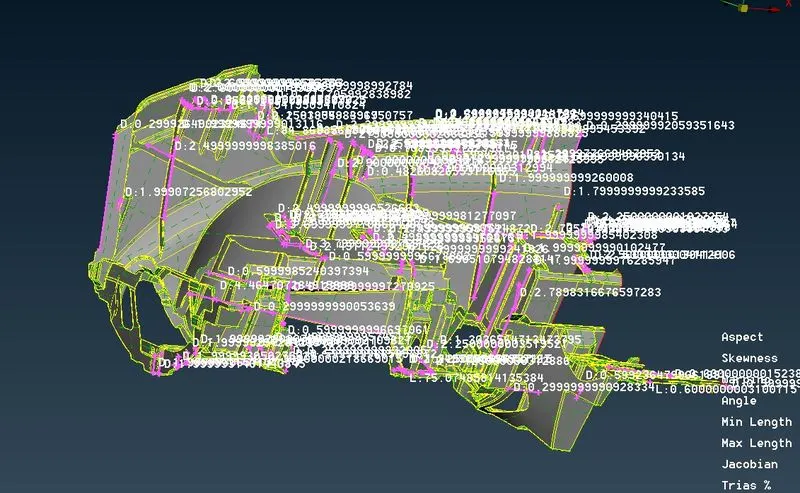
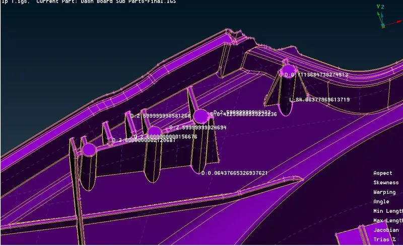
Mid-surfacing: For the given model in order to proceed with midsurfacing we measured thickness of all required components. Below image shows all measured faces on the model. Since the model is complex using Auto-mid is not feasible here.
For the faces having uniform thickness we used Faces>Offset>Faeture angle in this case in order to capture all similar faces we used an angle of 1 degree. Below images shows selection of faces and mid-surface. Since the thickness of edge elements was 0.60 we have gien offset of 0.30. The thickness was also assigned during this process
 .
.
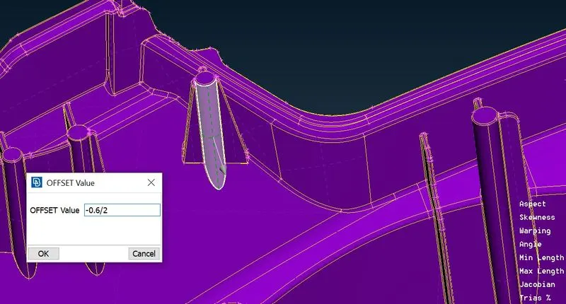
For parts like ribs we had to measure thickness for each feature and give offset accordingly. After measuring thickness we could give ofsset however, for cylinderical parts we had to take another approach. Since the top and bottom sides have varying thickness we had first find the average and then give half of the average as offset. For most cylinderical parts the average was around 0.60 hence we gave the offset of 0.30. Below images shows the same.
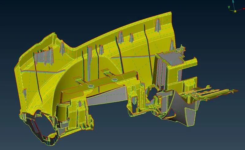
Once all the features were midsurfaced we extended them to neighbourng surface. The below images shows mid-surface of entire model and extending features.
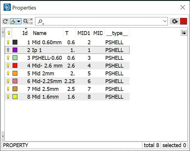
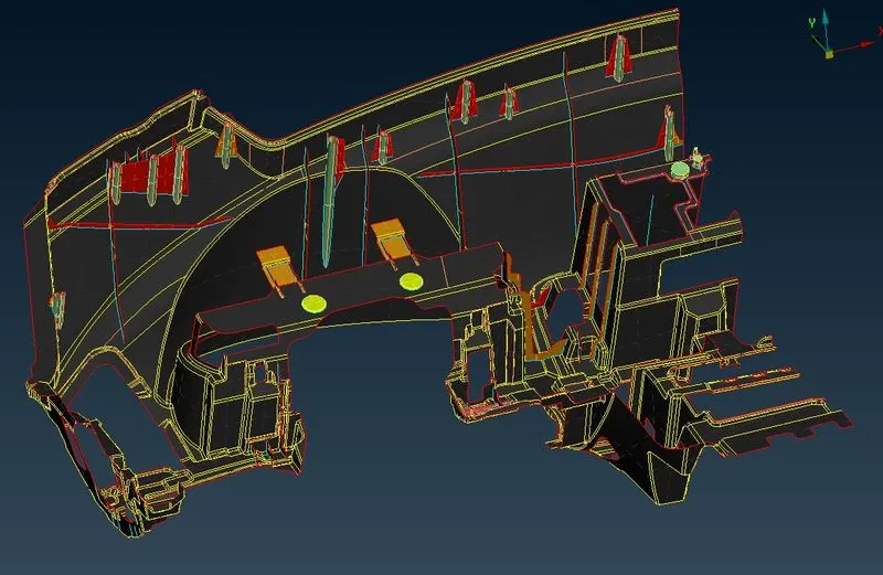
Afterwards, different PIDs were ceated and were assigned based on thickness of features. Below image shpws PIDs created and model after assigning PIDs.
Mesh Generation: For the given component we have been provided with quality criteria, hence we frst fed that into ANSA. Once the criteria is set we started with meshing. Since the given model is large doign all components by Spot meshing will be time consuming hence for the bigger part and large macro number we used Batch Mesh.
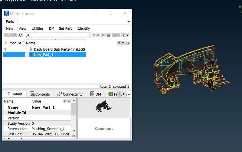
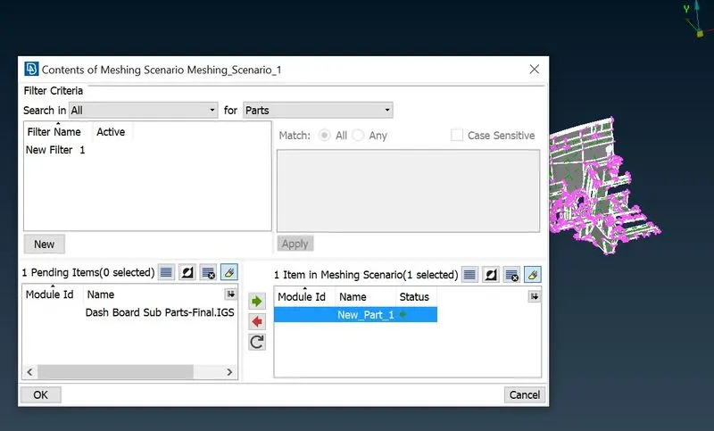
First of all we isolated the large using PID show only. Then in order to make sure Batch mesh manager selects part properly, we created a new part using Model Browser. Afterwards using Batch Mesh Manager we selected this component and created mesh of the surface. Below images shows the procedure.
For other features of model, we used Mesh Generation >Spot Mesh and Best Mesh tools. Here are few examples of the same.
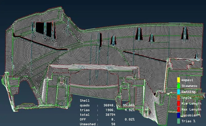
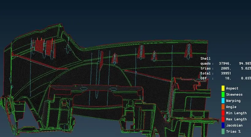
Mesh Improvising: Since the model has few overlapping surface and due to extending triple cons were formed on other surfaces, thus off elements wre created on the surface. To reduce the off elements to minimum possible number we used dofferent approaches like reconstructions, adding or removing nodes etc. Also, to keep proper mesh quality issues like roatating quads, oppo. trias and diamond shaped elements were reduced.
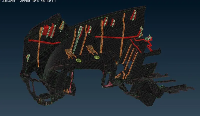
Below images shows final model before and after activating Draw Shell as Solid.
Before:
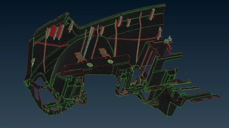
After:
Learning Outcome: By doing this project, we got an idea on how to approach to complex model, we learnt to use different mid-surfacing and meshing technique as per requirement.
Conclusion: Hereby, we have meshed the given model, by doing all required procedures, created mid-surface and meshed with given quality criteria.