Week 3 Sheet metal Bending challenge
Objective: Sheet metal bending is to be performed for 3 different materials mentioned below. Variation of certain settings is also to be performed and your conclusions are to be added to the report.
Procedure:
- Importing Geometry: The given model is imported and viewed in SpaceClaim for any errors. The model was without any geometrical error. The below image shows the model:
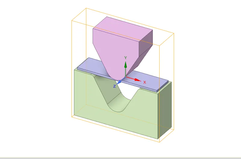
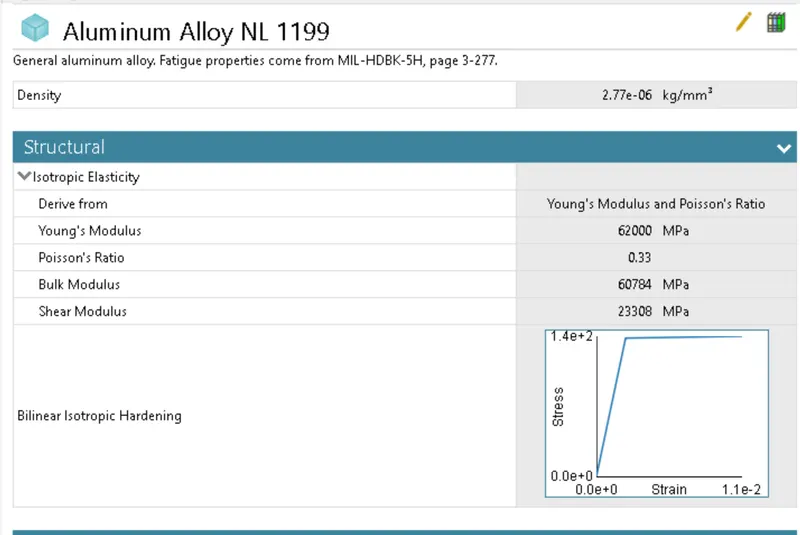
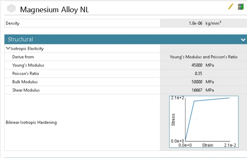
- Materials: For the first case we need to compare the results of solutions on three materials which are Aluminum Alloy 1199 Non-Linear, Copper Alloy Non-Linear, and Magnesium Alloy Non-Linear. Here we have selected the General Non-Linear Materials:
Aluminum Alloy Non-Linear 1199: Aluminium 1199 is a 99.99% Al minimum commercially pure alloy, possessing excellent electrical and thermal conductivity and corrosion resistance.
Copper Alloy NL: 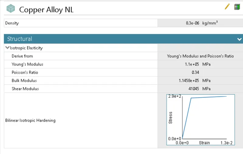
Magnesium Alloy NL:
- Setting Up Contacts: In the working of Die, Sheet, and Punch there is friction generated between die and sheet and between punch and sheet. We are required to define the contact in order to get accurate results:
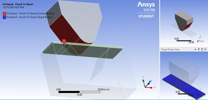
Between punch and sheet metal we have selected frictional contact between, here we have selected the faces of punch that will come in contact with the sheet and the top face of sheet metal was selected as the target surface. The below image shows the same:
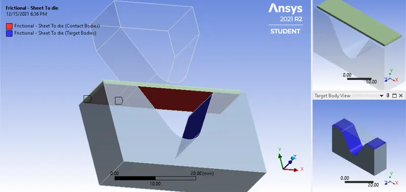
Between the sheet metal and die we have selected the surface of the die that will come in contact as the target body and the bottom face of the sheet metal. The below image shows the same:
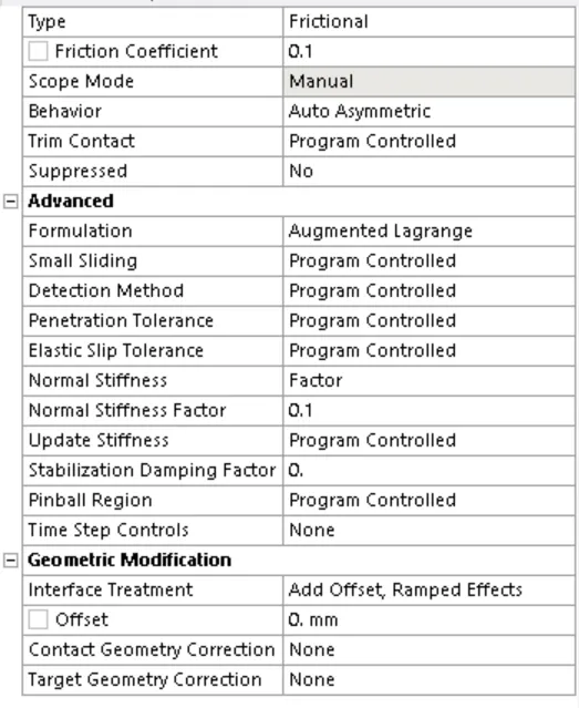
Here we have selected the contact type as frictional and kept the frictional coefficient as 0.1. We have selected Behavior as Auto-asymmetric. Change the formulation method as Augmented Lagrange and change the Normal Stiffness to Factor of 0.1 which is generally used in Bending Applications.
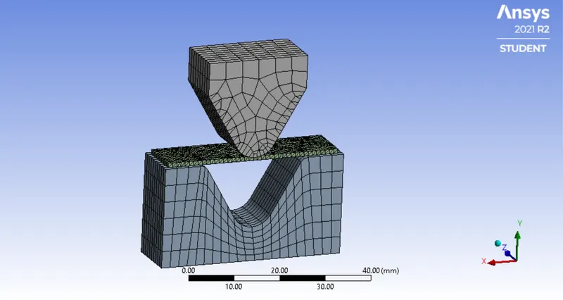
- Meshing: Here for better results we have used different mesh sizes in the model. The sheet, face die, and punch are meshed with the size of 1mm, and other faces are meshed with the size of 5mm. We have used Face Sizing to assign different mesh sizes to the faces. The below image shows the complete mesh.
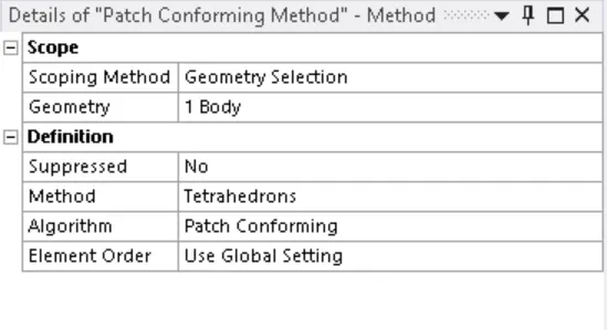
For the meshing method we have selected the sheet metal and used the Tetrahedrons as a method, below image shows the same;
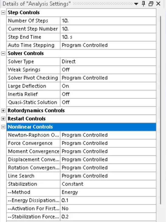
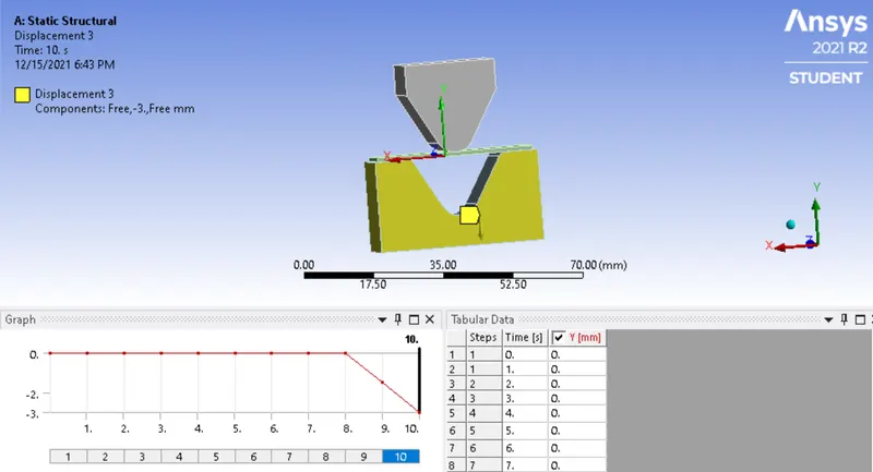
- Analysis Settings: The analysis was divided into Ten Steps. The large deflection is turned on to account for large deflection in analysis. We have used a Direct Type Solver. In order to keep material stable during the Analysis, we have selected the Non-Linear Stabilization method as Energy. The energy method sets the amount of energy allowed to be dissipated by damping.
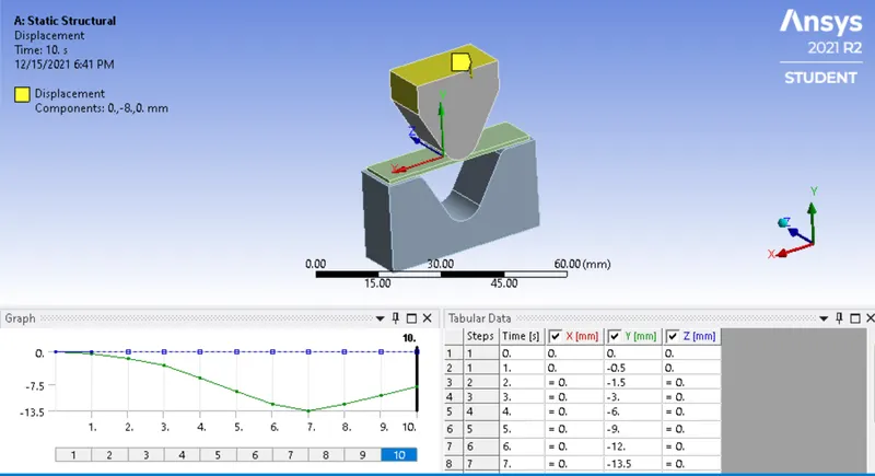
Punch Displacement: The punch will move from its initial position to the bottom of the die and then retract. We will give the displacement to top faces of die in the negative Y direction.
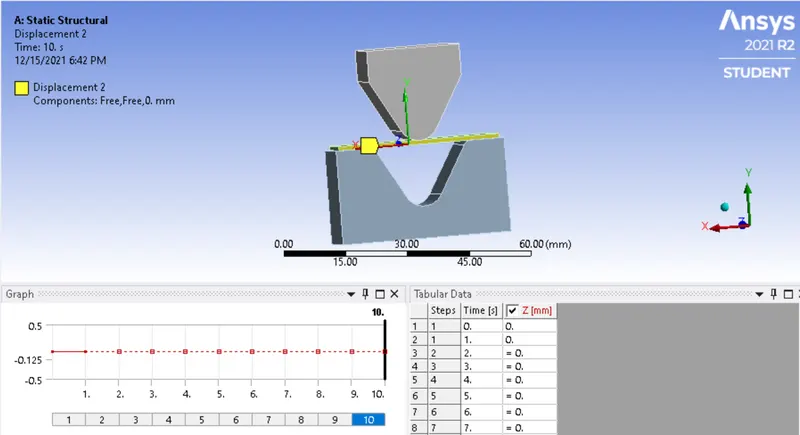
Sheet Displacement: Here we have fixed the sheet in Z-axis so that it does not move.
Die Displacement: The die will be staying in position for the majority of the analysis, however, once the punch reaches the bottom the die also disengages.
- CASE 1: Aluminium Alloy 1199, Copper Alloy NL, and Magnesium Alloy NL. Find out the Equivalent stress, Equivalent elastic strain, and Total Deformation in Y direction and compare the results for the three materials.
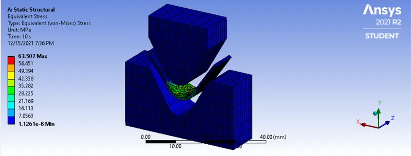
Analysis with Aluminium Alloy NL 1199:
Equivalent Stress:
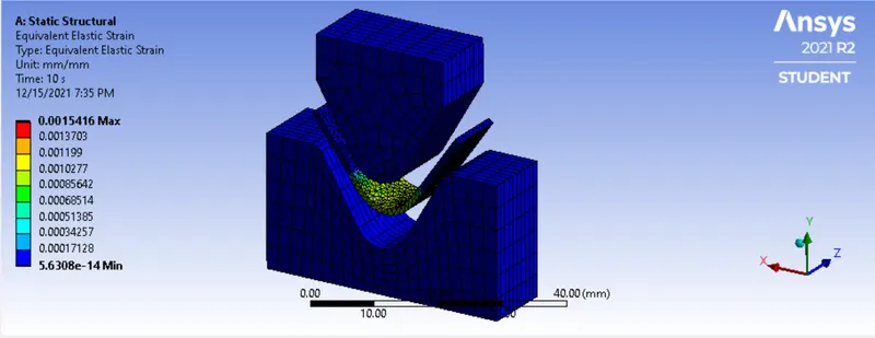
Equivalent Elastic Strain:
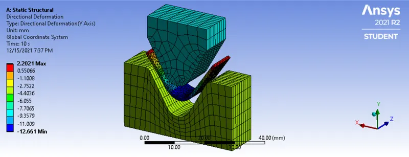
Deformation in Y-Direction:
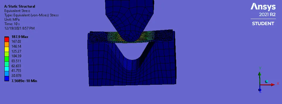
Analysis with Copper Alloy NL:
Equivalent Stress:
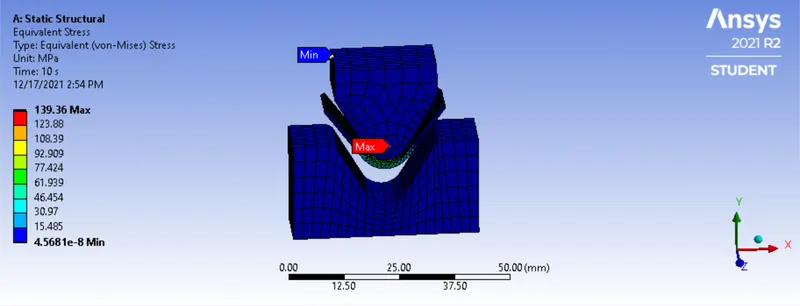
Equivalent Elastic Strain:
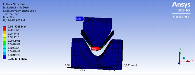
Deformation in Y-Direction:
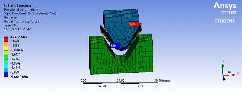
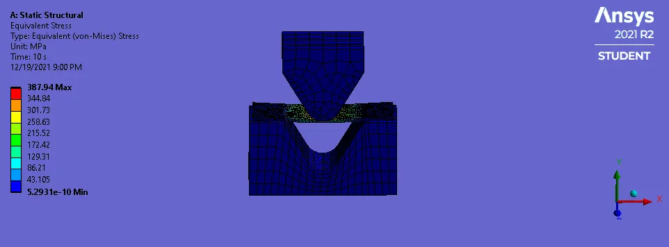
Analysis with Magnesium Alloy NL:
Equivalent Stress:
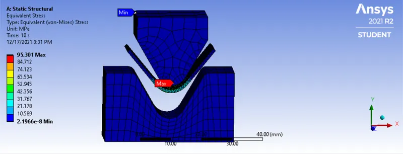
Equivalent Elastic Strain:
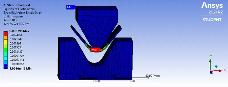
Total Deformation in Y-Direction:
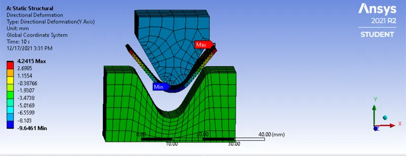
- Results:
| Materials | Aluminium Alloy NL 1199 | Copper Alloy NL | Magnesium Alloy NL |
| Min | Max | Min | Max | Min | Max | |
| Equivalent Stress | 1.1261e-008 MPa | 63.507 MPa | 4.5681e-008 MPa | 139.36 MPa | 2.1966e-008 MPa | 95.301 MPa |
| Equiv. Elastic Strain | 5.6308e-014 mm/mm |
1.5416e-003 mm/mm |
2.2871e-013 mm/mm |
1.7288e-003 mm/mm |
1.0986e-013 mm/mm |
2.796e-003 mm/mm |
| Deformation in Y Direction | -12.661 mm | 2.2021 mm | -9.6619 mm | 4.7732 mm | -9.6461 mm | 4.2415 mm |
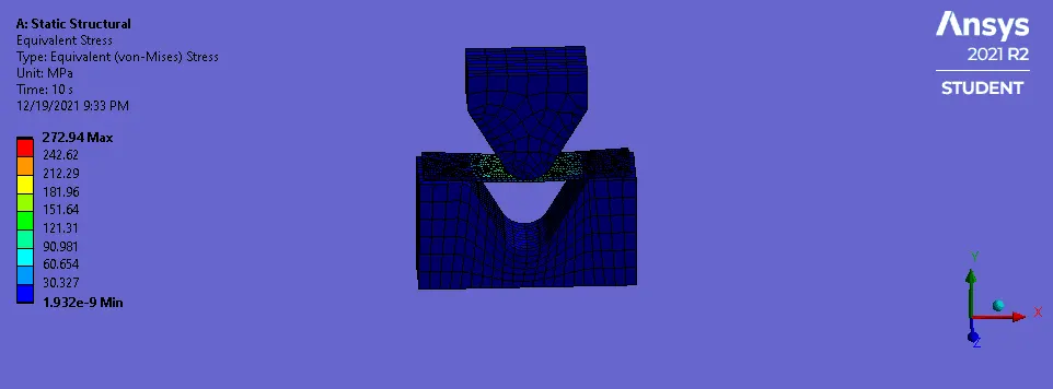
From the chart above we can see that the Stress is highest in Copper Alloy and least in Aluminium Alloy Similarly, the Deformation in Y-Direction is most in Copper Alloy and least in Aluminium. And the strain is highest in Magnesium and lowest in Aluminium Alloy 1199. From these results, it is clear that Aluminium performed the best, and is most suitable for Bending Applications.
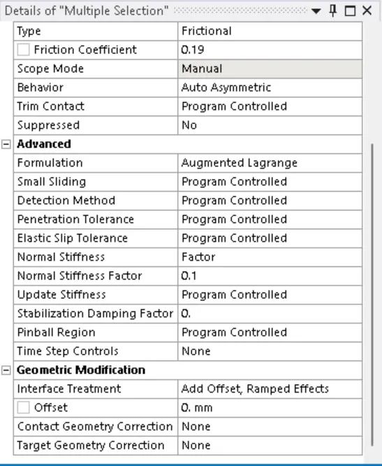
- Case 2:With the material as Aluminium Alloy, change the friction coefficient to 0.19 and run the analysis as mentioned in Case 1. Compare the results with that in case 1.
Here as per requirement, we have changed the frictional co-efficient to 0.19 below image shows the same:
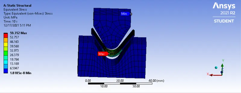
Equivalent Stress with Frictional Coefficient of 0.19:
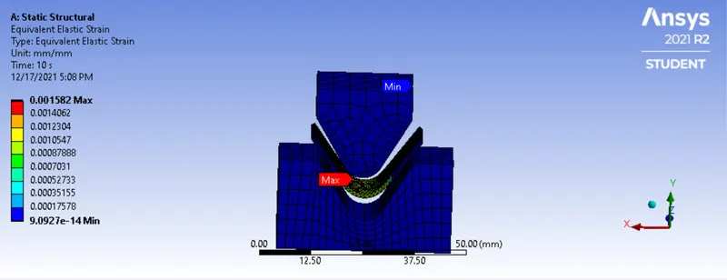
Equivalent Elastic Strain with Frictional Coefficient of 0.19:
Total deformation with Frictional Coefficient of 0.19:
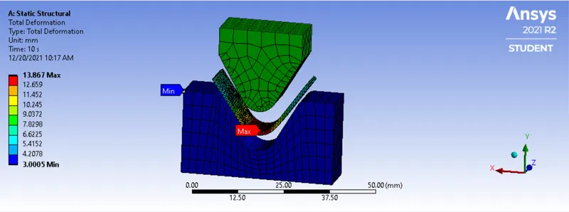
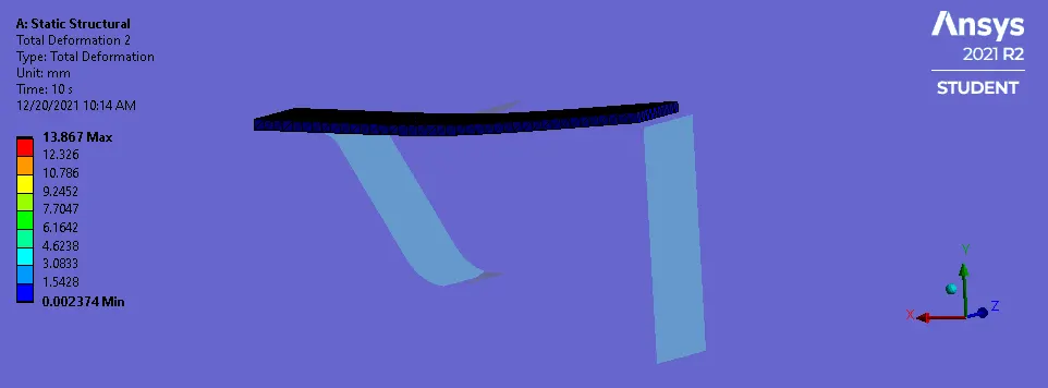
Conclusion: From the results above we can see that with a higher coefficient of friction the results achieved have more deformation. The stress and strain are about the same level however, there was a big difference in total deformation:
- Case 3: Refine the mesh on the plate such that it doesn't cross the academic limit. With Aluminium alloy as material, run the analysis as in Case 1 and compare the results.
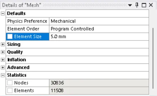
For this, we have refined the mesh of sheet metal with an element size of 0.8mm and also reduced the size for other faces to a size of 3.0mm such that we do not cross the academic Version limit.
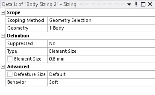
The mesh size was refined and the maximum node limit we got was 30836 which was under the Academic Version's limit.
Results:
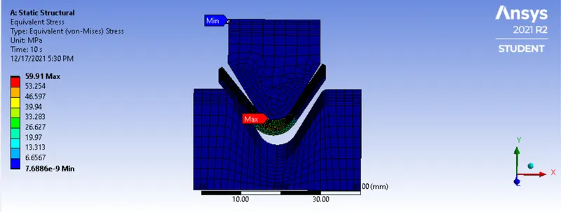
Equivalent Stress:
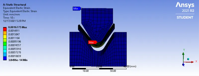
Equivalent Elastic Strain:
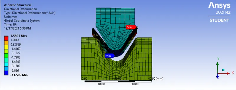
Directional Deformation in Y Direction:
| Refined Mesh | Regular Mesh |
| Min | Max | Min | Max | |
| Equivalent Stress | 7.6886e-009 MPa | 59.91 MPa | 1.1261e-008 MPa | 63.507 MPa |
| Equvi. Elastic Strain | 3.8496e-014 mm/mm | 1.6775e-003 mm/mm | 5.6308e-014 mm/mm |
1.5416e-003 mm/mm |
| Directional Deformation in Y Direction | -11.502 mm | 3.5805 mm | -12.661 mm | 2.2021 mm |
Conclusion: With finer mesh, we can get more accurate and more reliable results, however, with finer mesh the computation also increases.
Hereby, we have completed the analysis of all three cases and attached the steps and procedure of the same. We have compared the results as per requirement.