Creating 1-D elements with cross-sections and meshing using Hypermesh
Objective: Mesh the Given component with the Size of 5mm. Create 1D elements on the following component with given cross-section and DOF.
Procedure:
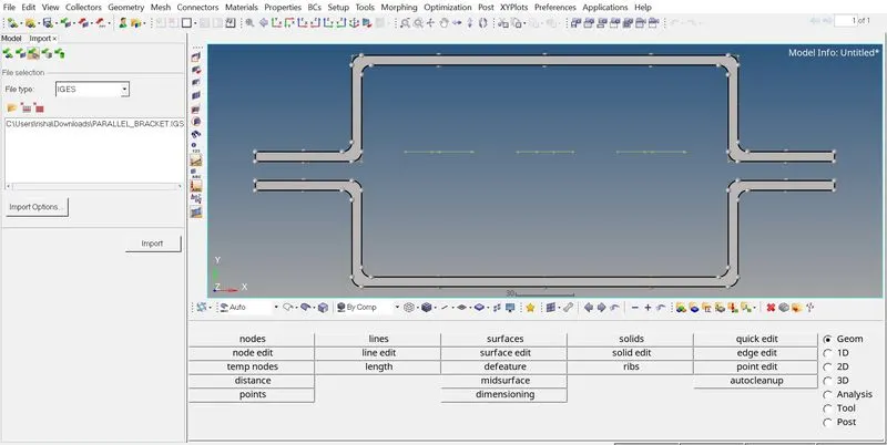
- Importing the model: The given model is in .IGES format, hence we need to import the model using Import tool>Import Geometery>IGES>Import. The below image shows the same.
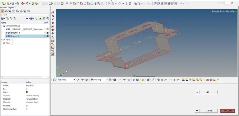
- Creating Mid-surface: Once the model is imported we need to create the mid-surface. For doing so we will use tool Geometery>Midsurface>Automid. We will select the the surface of the bracket and confirm. For the given model we used Ofsset+Planes+Sweeps for feature capturing. We repeated the procedure for the other part of bracket. Once the midsurface was generated we deleted the geometery and wireframe model. For each part of bracket we will asiign a different part in Model Browser. The below image shows the midsurface created.
- Creating Properties: In order to apply thickness to the midsurface we will assign a different Property for each component of bracket. As both components have similar thickness we have assigned thickness of 2.5 to both the properties.
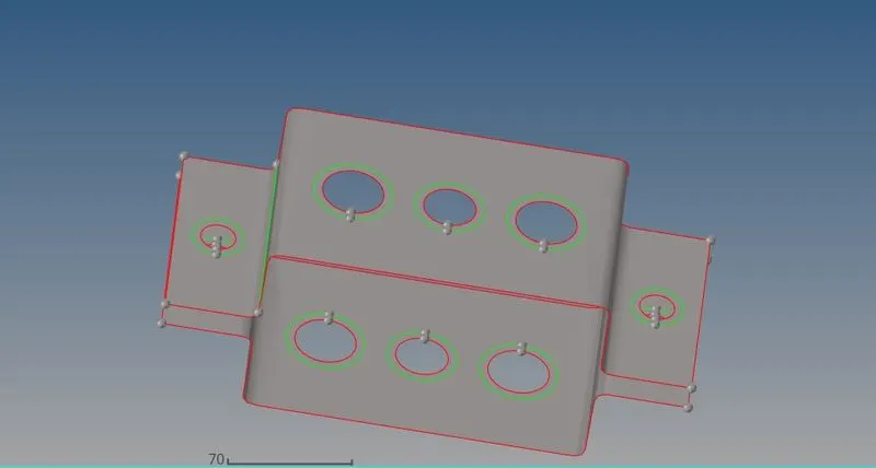
- Creating Washer Split: In order to get better mesh flow around the hole features we created washer split with a distance of 5mm. We used tool Geometery>Quick Edit>Washer Split. Below image shows the washer split created on hole features.
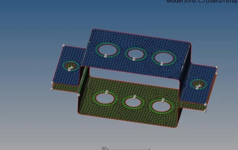
- Mesh Generation: For creating mesh on the surface we used 2D-Automesh as per requirement we used element size of 5. We used only Quads for the mesh. The below image shows the mesh generated. For improving mesh in washer split region we increased number of nodes at edge to match the number of nodes at inner line and then remesh the region to get better mesh.
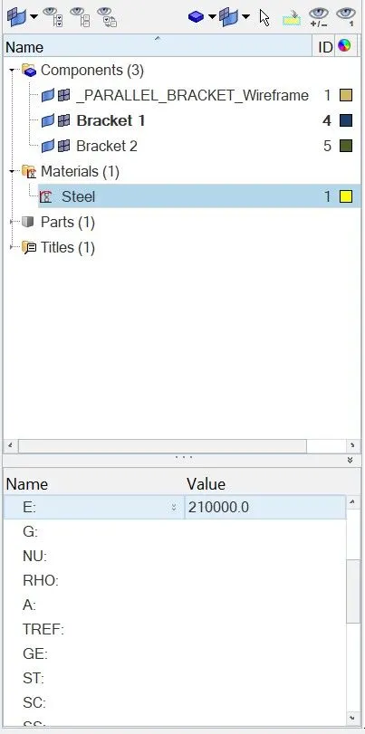
- Creating Material Properties: The material is assigned to model in order to get desired result during analysis, in this case we have used MAT1 card as STEEL. When a card is slected various material property such as Young's Modulus, Poisson's Ratio etc is also asssociated with the model. Once the material card is created we can assign it to the properties. The below image shows the material card assigned to the model.
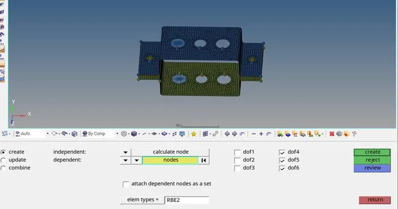
- Creating Links on A, B & C: As per the requirement, we have to create RBE2 and RBE3 links on the three hole features.
RBE2 link for A: Only translation motion are constrained, rotational DOFs are free.
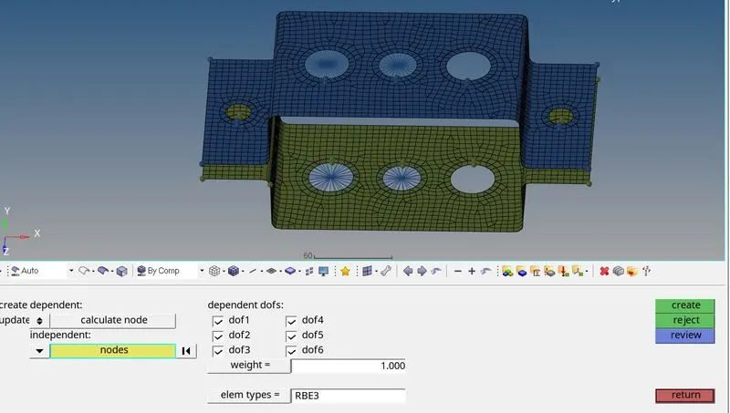
RBE3 link for B: All DOFs constrained.
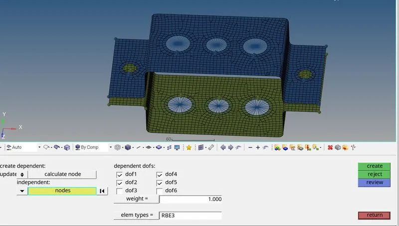
RBE3 link for C: Z-axis roation and tranlation free. Only X&Y motions are constrained.
At point D,E and F we created RBE2 rigid link.
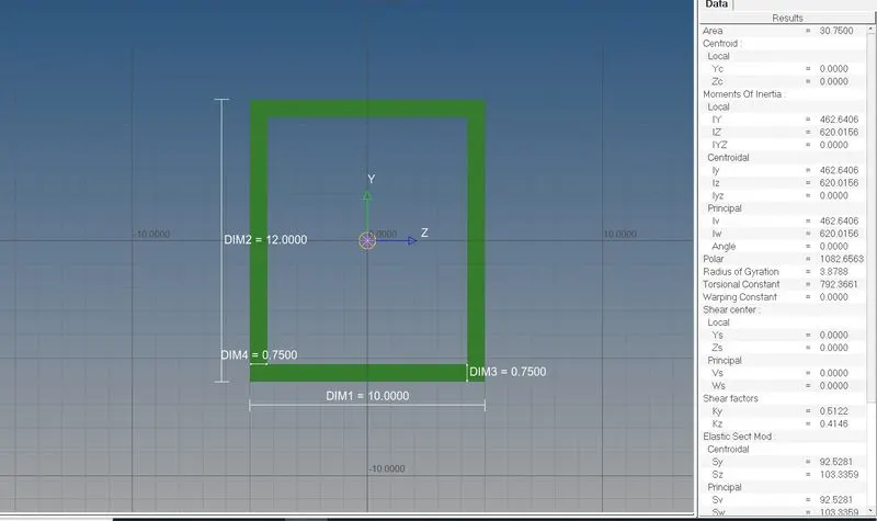
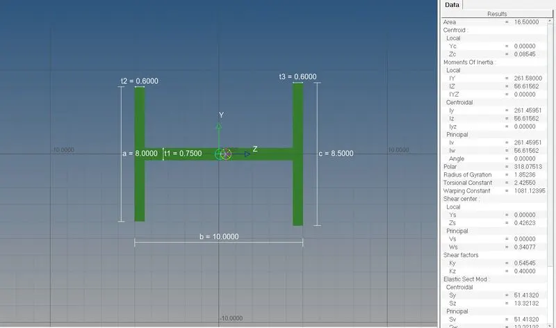
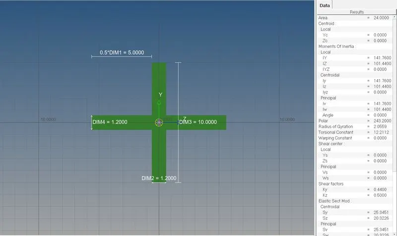
- Creating Cross-Section Elements: In order to create cross-section elements we will use 1-D>Hyperbeam>Standard Section.
Specification of Box Section: Dimension a= 12 mm dimension b=10 mm Thickness t= 0.75 mm
Specification of I-section: Dimension a= 8 mm, Dimension b= 10 mm, Dimension c= 8.5 mm, Thickness t1= 0.75 mm, Thickness t2= .6 mm, Thickness t3= .6 mm
Specification of X-section: Dimension DIM1= 5 mm, Thickness DIM2= 1.2 mm, Dimension DIM3= 10 mm, Thickness DIM4= 1.2mm
- Creating 1-D Elements:
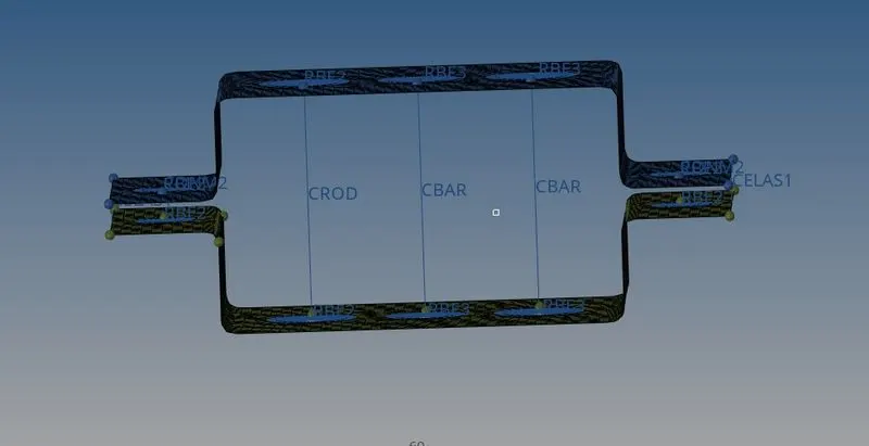
For Rods: In order to create Rod element we will use 1-d>Rod>Select center nodes of RBE2 link created at A>Create.
For Beam: For creating beam element we will use 1-D>Bar>Select element type as CBeam>Select center nodes of RBE3 link created at B>Select Orientation nodes>Create. Initially we selected Bracket 1 as property.
For Bar:For creating beam element we will use 1-D>Bar>Select element type as CBar>Select center nodes of RBE3 link created at C>Select Orientation nodes>Create. Initially we selected Bracket 1 as property.
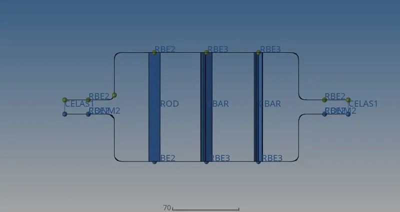
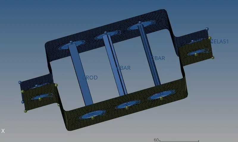
Below image shows all three 1-D created on the model.
- Creating Properties for 1-D elements: We will create three properties namely bar, rod and beam. Then in card edit we will select the respective Cross-section for the same, we will change Card image, for Rod we will select PRod, for bar PBar and similarly PBeam for beam.
- Applying mass and Creating Spring Element: At point D and E we applied a mass of 10 units using 1-D>Mass>enter mass unit>slect element type as CMASS1.Select one property. For creating Spring element to join two components we used 1-D>Spring>Select one node on edge on each component>Create. Below image shows the same.
- Updating Properties for 1-D Elements: Now in order to see all above changes we will go to 1-D>Rod>Update>Change property to Rod from previously selected one. Similarly for Bar and Beam we will 1-D>Bar>Update>Change property to Bar/Beam from previously selected one.
Once all the requirements of model are completed we can see all cross-section asssigned to 1- elements by going to 1-D element view and change it to 1-D Detailed and traditional View. Below are final images of the model.
- Conclusion: The given model has been modelled by creating midsurface, doing 2-d mesh. cross scetion was created with given dimension. 1-d elements were created and respective cross-section was assigned to the same. Spring elements was cretaed to connect two components. RBE2 and RBE3 links were cretaed with respectove constraints for Dofs.
- Learning Outcome: By completing this challange we learned to create cross-section, creating properties, asssigning material to components. Creating 1-d connections and using RBE2 and RBE3 links.