Week 4- Rolling operation
Objective: For this challenge, we have to simulate the rolling operation on a workpiece made of copper. The model is provided. Increase the length of the workpiece by 60mm and decrease its size on both sides by 8mm. Run the simulation for 14 steps and you can give small but random values( similar to the ones mentioned in the video) for the displacement. Ensure that the edge of the workpiece is displaced by 90mm.
Cases:
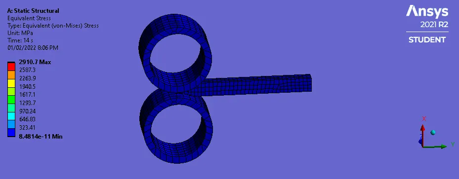
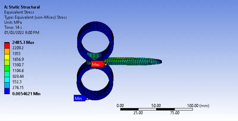
- Equivalent stress for the whole setup
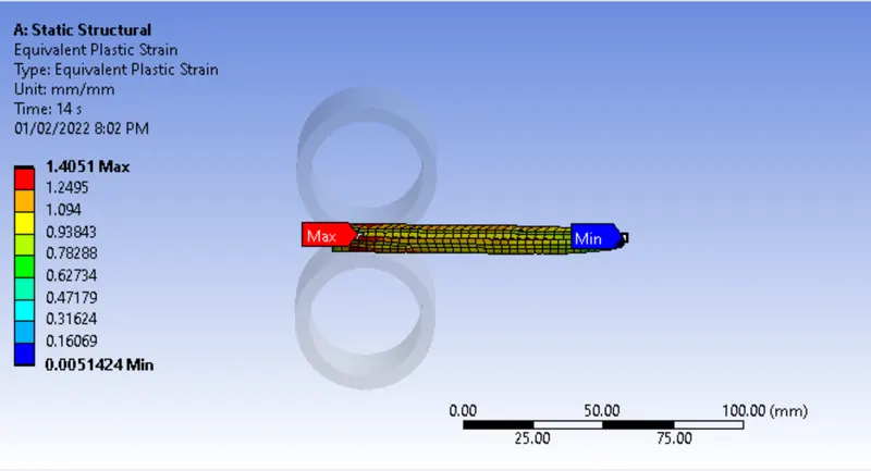
- Equivalent Plastic strain for the workpiece
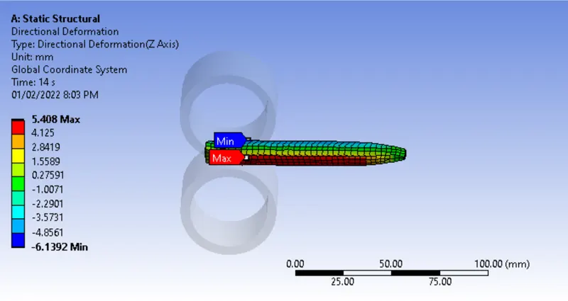
- Directional Deformation in the Z-axis for the workpiece
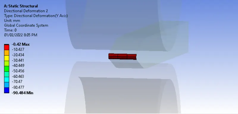
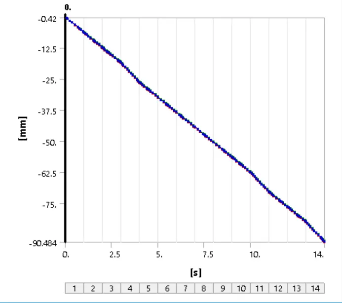
- Prove that the workpiece has been displaced 90mm.
Procedure:
- Importing & Editing Geometry
- Adding and assigning Material
- Setting Up Contacts
- Meshing
- Setting Boundary conditions
- Results
We will start with the setting but static structural analysis in ANSYS
- Importing & Editing Geometry: The model is given in the challenge can be imported in the ANSYS and as per the requirement we have to edit the geometry. We have increased the length by 60mm and reduced the width from each side by 8mm. We can alter the size using the Pull tool from Spaceclaim, the below images show the geometry before and after editing:
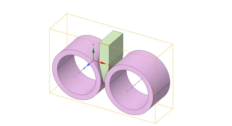
The below image shows the option to increase or decrease the size of geometry using the pull tool, using the same tool we will decrease the width of workpiece.
The below image shows the final geometry: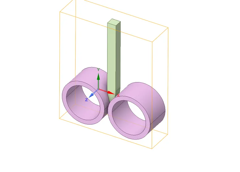
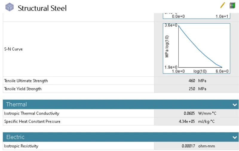
- Adding and assigning Material: For the model, we will use Structural Steel and Copper. We have used copper for the workpiece and steel for the rollers
Copper:
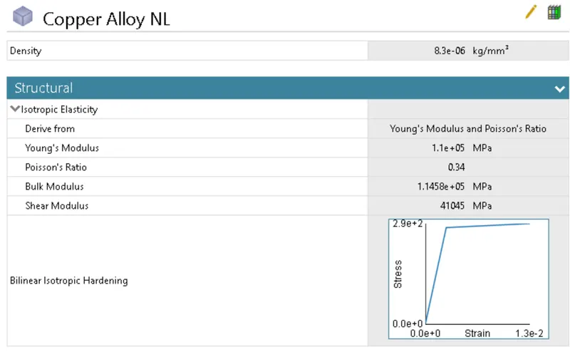
Structural Steel:
- Setting Up Contacts: We will start with flipping the contacts, we changed both the contacts between rollers and workpiece to Frictional and changed the coefficient of friction to 0.2. Below image shows the method:
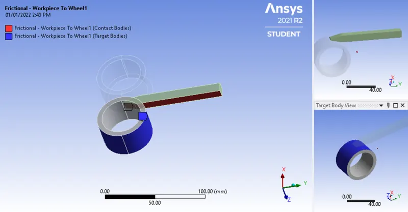
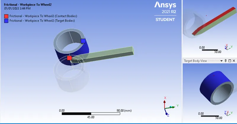
Similarly, we define the Joint for the two rollers, we will define the rotational joint by selecting the inner face of the rollers.
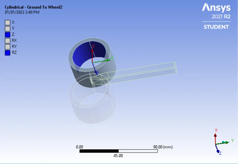
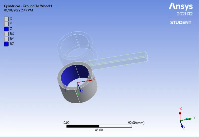
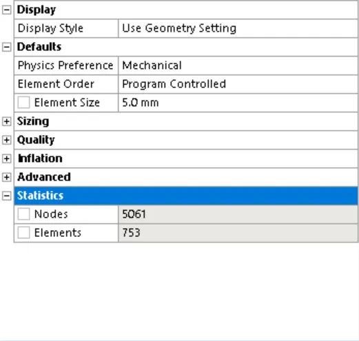
- Meshing: We have meshed the rollers with 5mm mesh and workpiece with the size of 3 mm using face sizing. Below image shows the same:
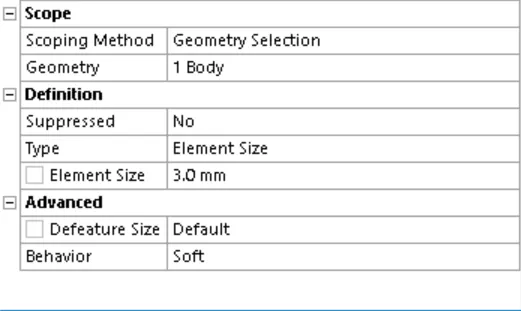
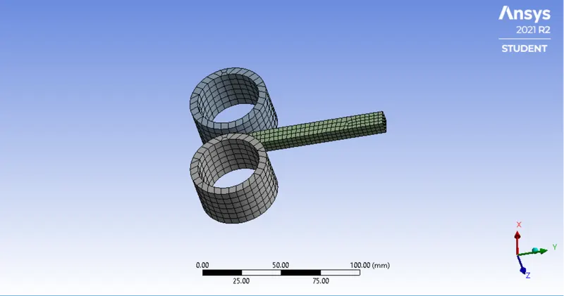
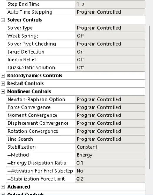
- Setting Boundary conditions: As per requirement we will run the simulation for 14 steps, we will enable the large deflection and
Deformation: In order to feed the workpiece to the rollers, we will select 2 faces on opposite sides and move it to the negative Y direction, we have given random values up to -90mm,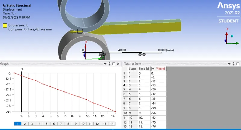
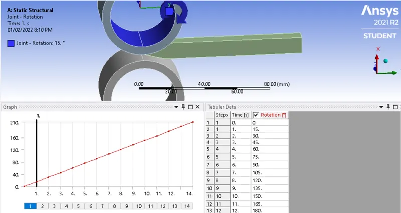
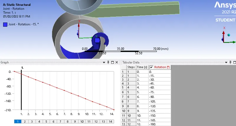
Rotation Joints: We will select a Cylindrical joint for the two rollers. Give type as Rotational and DOF as Z Rotation and Magnitude as Tabular Data. We will enter the 15-degree rotation for each and total rotation of 210 degrees, below images, shows the same:
- Results:
Equivalent stress for the whole setup:
Equivalent Plastic strain for the workpiece:
Directional Deformation in the Z-axis for the workpiece:
Prove that the workpiece has displaced by 90mm::