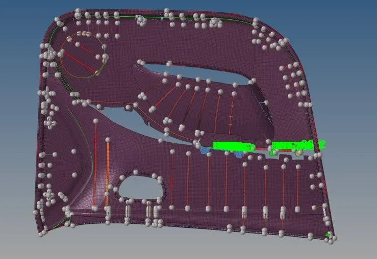
Project-1-Meshing of Door Inner Panel using Hypermesh
Objective: Mesh the Side Door Plastic model with given quality criteria and assign the thickness.
Quality Criteria:
Target Element Length = 4 Units
| S.N | Quality Criteria | Value | |
| 1 | Aspect Ratio | 5 | |
| 2 | Skewness | 45 | |
| 3 | Warping | 15 | |
| 4 | Taper | 0.5 | |
| 5 | Min. Length | 2 Units | |
| 6 | Max. Length | 6 Units | |
| 7 | Min angle Quad | 45 | |
| 8 | Max angle Quad | 135 | |
| 9 | Min angle Tria | 20 | |
| 10 | Max angle Tria | 120 | |
| 11 | Tria % | 10 |
Procedure:
- Import
- Geometery Cleanup and Defeaturing
- Midsurfacing
- Extending Surfaces and Midsurface cleanup
- Meshing
- Element Cleanup and Mesh Improvement
- Assigning Property and Thickness
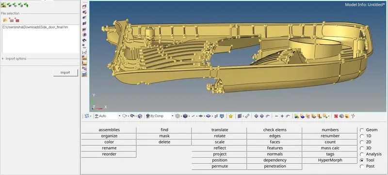
- Import: The given model is in .HM format, hence we can diretly import it through files, we can allso use Import Tool>Model> Select File> Import. The below image shows the same.
- Geometery Cleanup and Defeaturing: To get a proper midsurface we will ensure there are no issue with the Geometery, we will start with changing the view to Wireframe, below image shows the same.
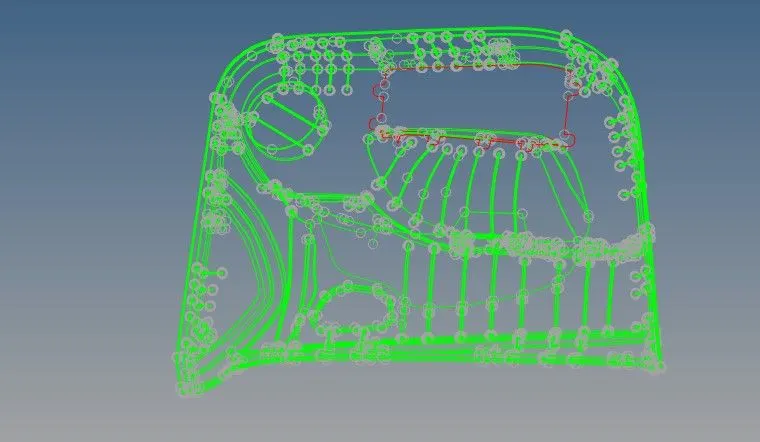
By changing the view here are the few issues we found through the wireframe mode. Which can fix by toggling lines or using Edges>Replace.
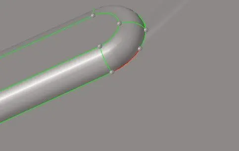
Once all he free edges are resolved, we checked for any duplicate surafce or surafec with issues, in current model we did not find any such issues. Hence we proceeded to check for surfaces which may cause min lenght issues which meshing and toggled the lines there.
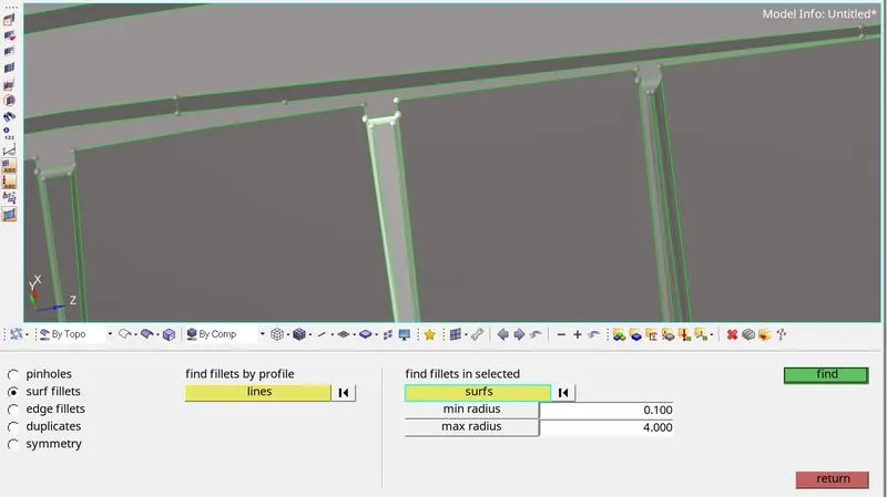
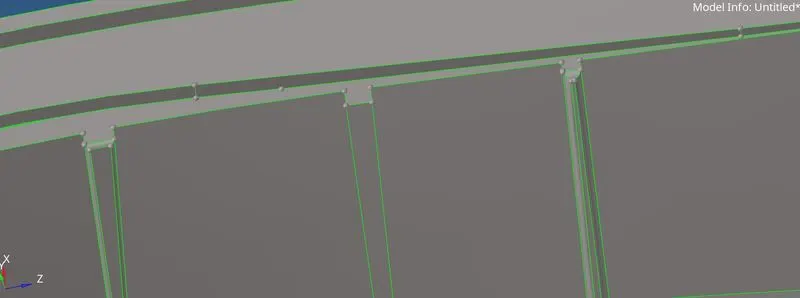
To get propeer feature capturing of surfaces like Ribs we will defeature the surface fillets. To do defeature we will use option of Geom>Defeature>Surf Fillets. The below image shows the procedure, we will repeart the same for all the ribs.
Before
After
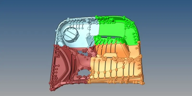
For better handling of the model we will divide the model in 4 parts, below image shows the same.
One the defeaturing and geometery cleanup is done we can proceed for creating midsurface.
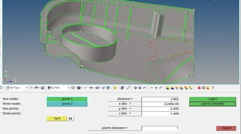
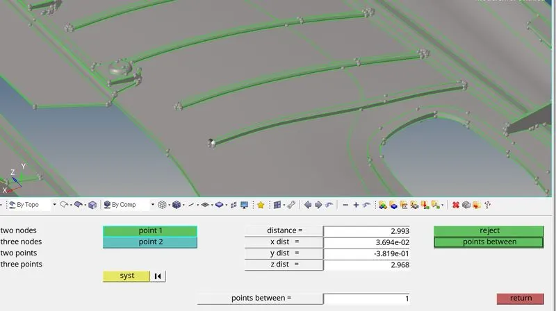
- Midsurfacing: In order to create the mid-surface we fiest need to know the exact thickness of the surface, to know the thickness we will use Geom>distance tool. The below image shows the same.
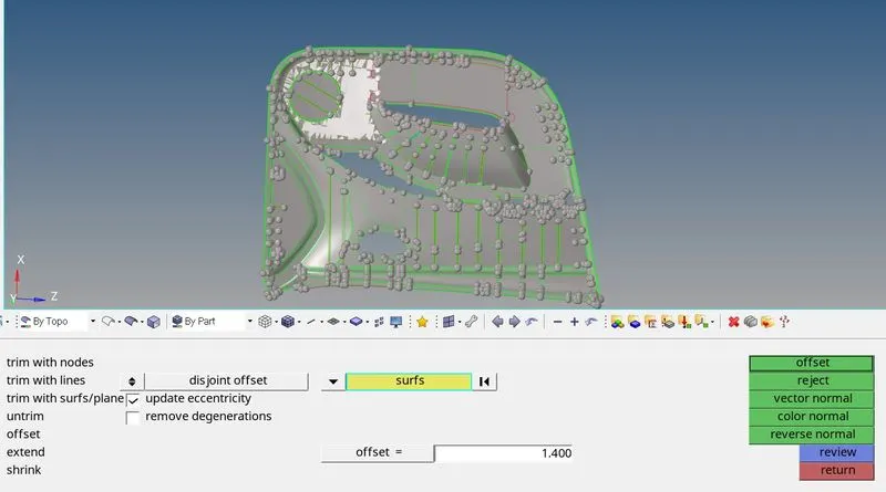
Now to create the midsurface we will use Surface Edit>Offset tool. We will create a component for the midsurface, here we have named the component based on thickness that needs to be applied. For example isn shows surface we created a component with name MID2P8mm and made it current component. Once the compoent is created we will select the surface duplicate it to current component. The beow image shows the procedure.
Before confirming we will check the Vector normal, it should be towards the center of surface, based on selected surface whether it is top surface or bottom we can change the vector normal by reversing it.
For creating midsurface of portion of Ribs we have two dofferent methods, here are examples of both.
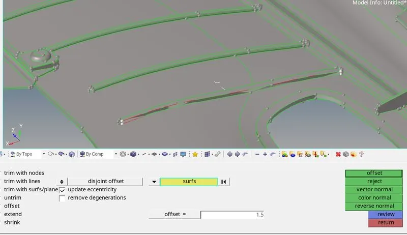
Firstly we used one side of the rib and offsetted it to the middle. First we measured the thickness of the rib, once done we will proceed to create a component with thickness of same name and make it current compoenent. Then we will go to Surface Edit>Offset select one surface, duplicate it and offset it to the middle. The beklow image shows the procedure.
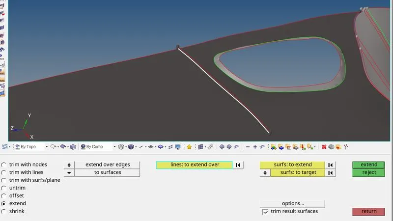
Once the surface is generated we have to extend it to base surface. We will use Surface Edit>Extend> Lines to Extend>SUrface to target>Extend. Beow image shows the procedure.
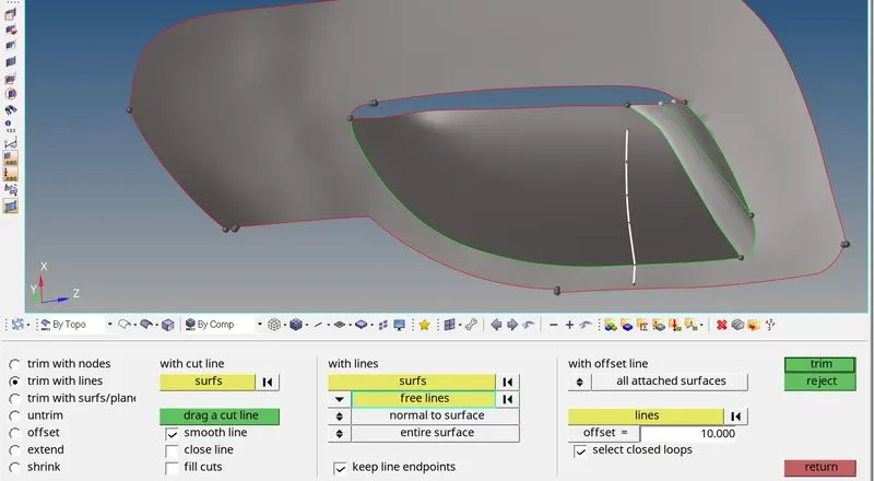
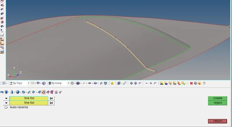
For another method we have to create a midline. First we will create midline using Line Tool, once done we will trim the mid surface using the line. For this we will use Surface edit>Trim with line>Select surface and Line>trim.After that we use both the lines to create a surface using Surface>Ruled Option. Below image shows the procedure.
- Extending Surfaces and Midsurface cleanup: Once the midsurfaces are created we will connect the surface using toggle option from Quick Edit and replace Edge option. below image shows the same.
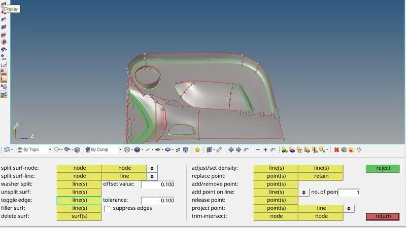
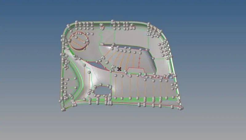
We will clear any surface issues. Using the above shown method we will create midsurface for entore model. The below image shows the midsurface so generated.
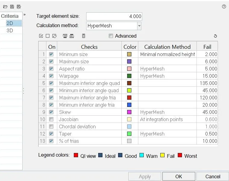
- Meshing: For meshing the surface we will first enter the qualityciteria in Prefernece > Quality Criteria. And we will save this is a a file so that we can access it quickly. The bwlo image shows the same.
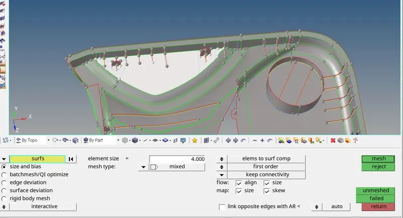
For meshing we will go 2D- Automesh>Surface, we will select the surface change target element lenghr to4 and mesh. Below image shows the same.
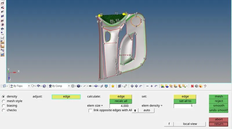
For meshing of ribs we selected the surface, meshed and corrected number of nodes so that no tria is on the ribs. The below images shows the same.
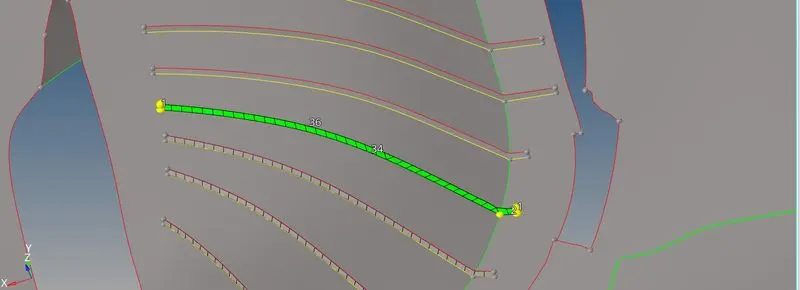
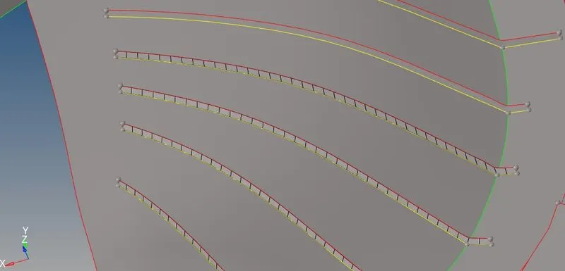
Similarly we will mesh rest of the surface. We corrected the mesh flow for each surface after meshing.
- Element Cleanup and Mesh Improvement- After the meshing is completed we will look for quality issues with the mesh. To remove the quality issues we can choose to either Remesh the elements. or fix them using Cleanup Tool from Quality Index.
The below image shows the method and results.
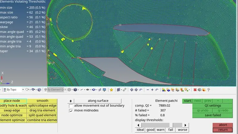
By using Smooth, element Optimize and remeshing we will fix the issues, the below image shows the results.
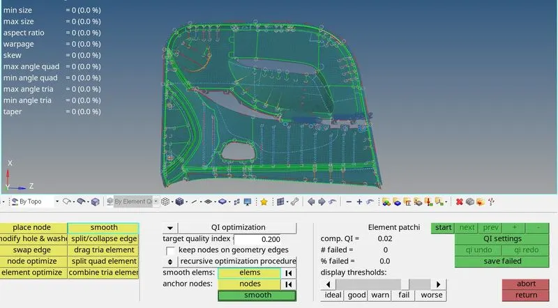
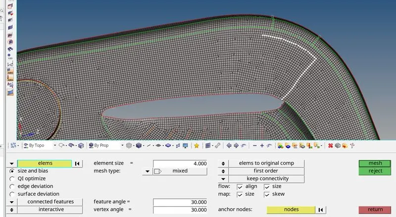
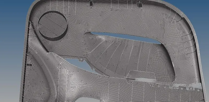
For improving the mesh and reducing tria elements we can Smooth, element remesh and drag tria tools to get a better mesh flow, below image shows the results. For a better mesh on this model, the ttria percentage was reduced to 1.7%. The below image shows an example, similar methods are used on all the surfaces.

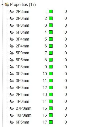
- Assigning Property and Thickness: Once the meshing is done and mesh flow is improved we will create properties for each thickness size in the model and enter the thickness. Once the propertoes are created we will assign property and material to the components. Hence in thiss way we can assign the thickness to the components. Below images sows the same.
Entering thickness: After creating property we will assign the thickness to it.
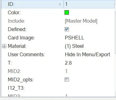
Creating Properties: For each component of different thickness we have created a property and applied a thickness of respesctive component.
Once done we will apply te property to the components. And to view the model with thickness applied we can shange the view to 2d Traditional and Detailed View. Below image shows the same.
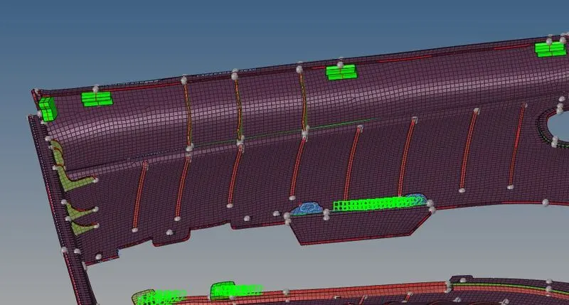
(Note: Mid-surface of two ribs are not properly aligned, various method were tried and support session was attended but the issue could not be resoolved.)
- Learing Outcome: By completing this model we learnt about manual midsurfacing, and meshing. We learned about modelling of plastic component such as given model. We also learnt about applying thickness and assigning it to component.
The below image shows the final result.