Week 6 - Connection Modelling of Rear Door using ANSA
Objective: Implement connections for the given FE model of the rear door. Using techniques shown in the video. Also, write a report explaining types of connections used for the model.
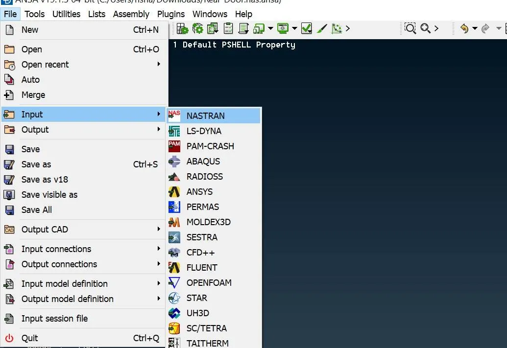
Importing the model: The given FE of the rear has been provided in .nas file in order to import the respective file to also we fill got to FILE>Input>NASTRAN> Open the folder where the file is located and open.
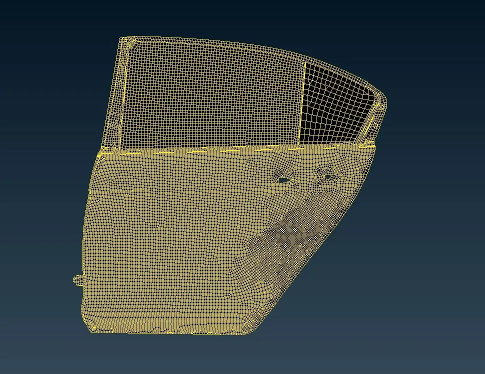
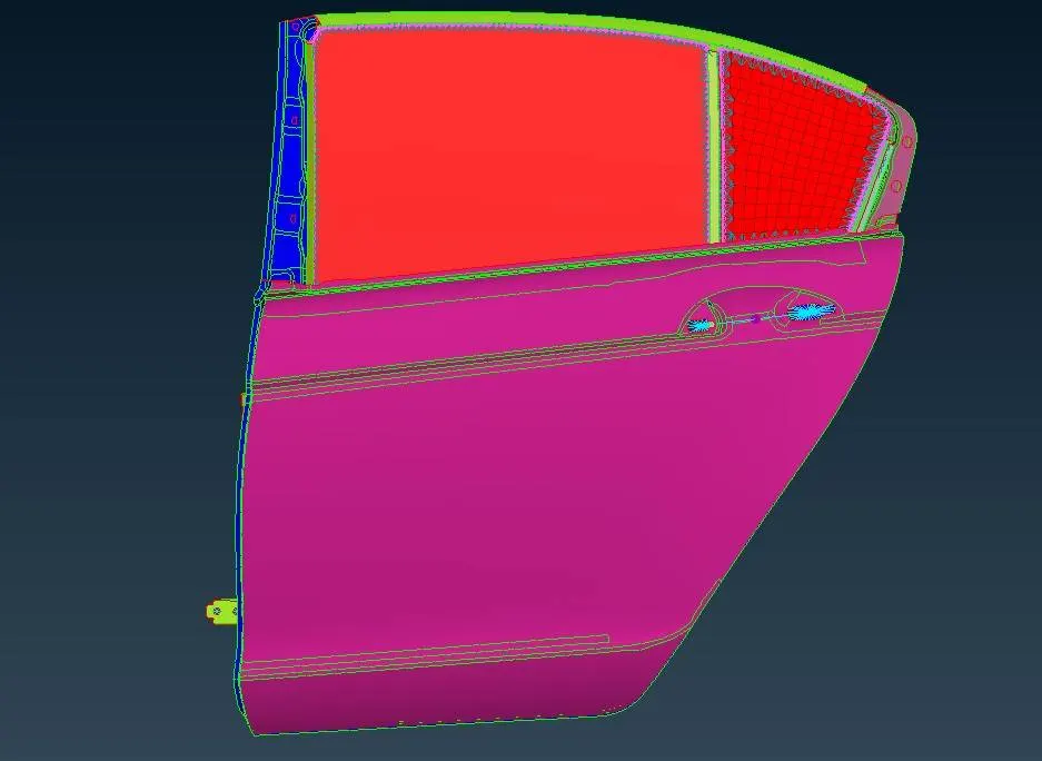
Assigning PIDs: The provided model has been given in single PID for entire model. However, in order to estalish connections properly we require proper PIDs. Thus, by isolating the parts using Boolean operations. And PShell property assigned for respective parts. Follwing are images of model before and after assigning PID.
Before
After
Connections: In order to prepare the model for NVH simulations it is important for us to establish connections on the FE model. The given model of the rear door was prepared using maily three type of connections i.e. Bolts, Spot Weld and Seam Weld.
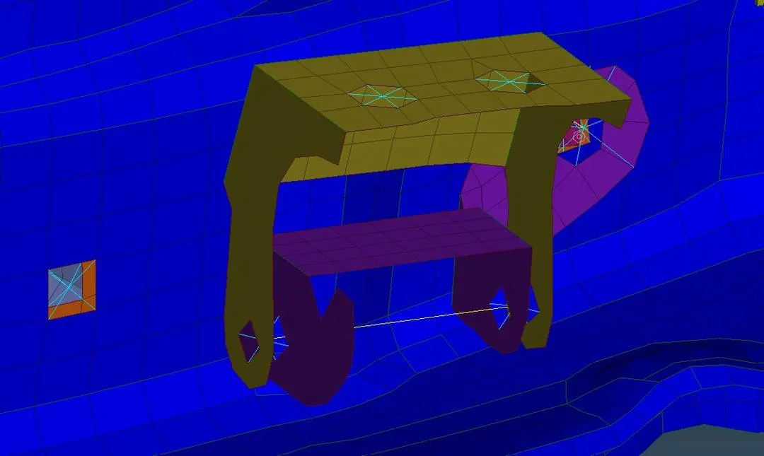
Door Latch: Firstly, we made connections for the door latch. We have to make proper connections at both the latches. Starting with making connection with door latch and latch plate, as there has been hole provided for the bolts. We provided RBE2 connection using MANY NODES option on both sides. After that we will connect both master nodes with two node RBE2.
Now in order to door to operate in normal conditions we will remove universal Z-direction for the DOF. For that we will go to NASTRAN>Elements>Info.> Select the Two Node RBE2 connection between latches and middle click and we will remove Z- direction from CM i.e. number 6. Similar steps would be followed for the second latch. The below image shows the connections made between door latch.
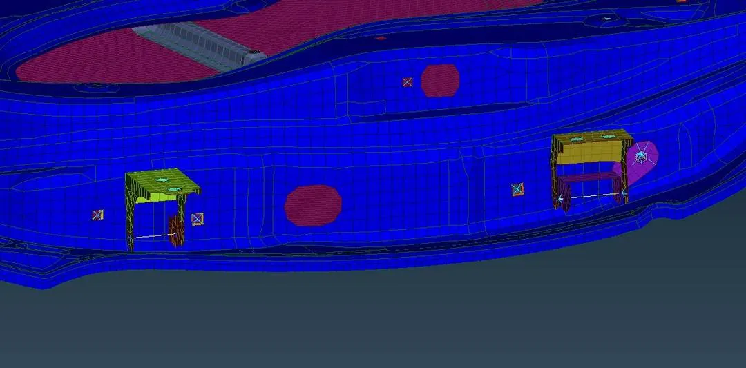
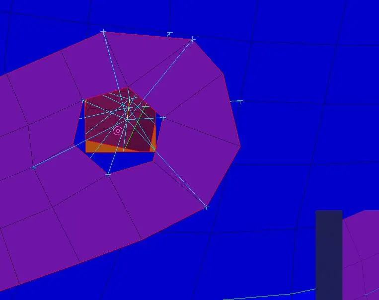
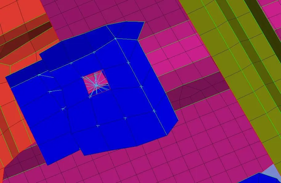
Bolt Connections: Now for the parts where other components are attached and a hole has been provided for the same, we used RBE2> Many Node connection and joined using a master node. These connections are used where two parallel surfaces have a hole provided. The bolt connection are either provided by using the above method or it can be provided by first creating a 3-D point and then converting it into bolt. After that we have to select the parts PID which needed to be connected. For FE Rep type we will use Bolts. The below images shows both bolt connections used.
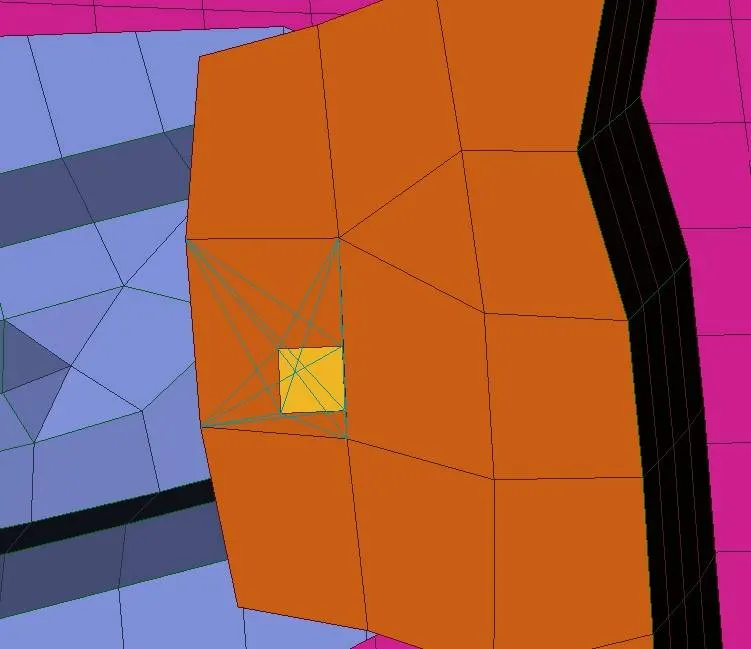
Spot Weld Connections: This type of connection is used between two parallel surfaces overlapping each other, In order to establish a spot weld connection, we first have to create a 3-D point at any of the two surface. Now in order to realise the we have to convert it into spot weld, and then using connection manger and choosing FE rep type as RBE3-Hexa-RBE3 and slecting the two surfaces we can made the spot connection. Below are the images of the same.
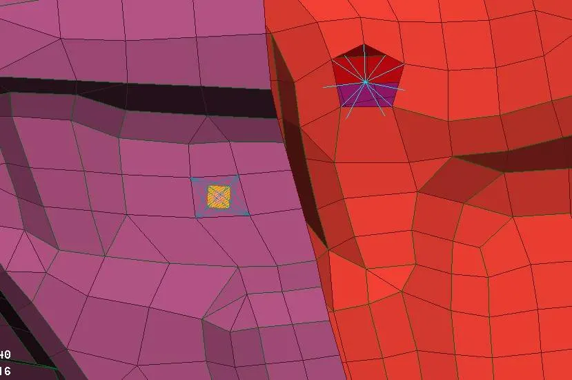
Connection on Window and Quarter-window- The windows in actual practice are surrounded by weather strips however, for FE representation we can not use that. Firstly, we will convert the feature lines of the window into curve using FEATURE to CURVE. Now for each curve we will convert it into spotline using convert tool. Using the connection manager we will select the curve. Now, we will select PID of each part to be connected. We will give spacing as required between two elements.
In FE rep we will select RBE3-Cbush-RBE3, we will given search distance and enter PBUSH ID and apply to project the elements. The same will be done for rest of the sides. However,, for lower window panel, we will copy the curve to create elements in both sides. It is done to represent the damping member.
In similar manner Cbush connection can be given on all sides for quarter window glass.
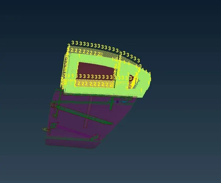
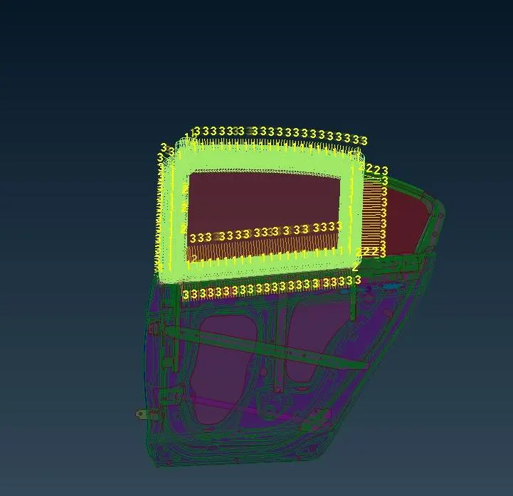
Correcting Orientation: After all bushing connections have been realised we have to change the orientation vector of all Cbush elements, it is done to keep the co-ordinates of all the elements to be aligned with the global co-ordinate of the vehicle. In order to change the orientation from with vector to with co-ordinate, we have to go to Database>Elements>Select all>Modify>Select orient>with cord>Select CID> enter given CID in this case we have taken 0. The below image shows the results of before and after changing orientation.
Before
After
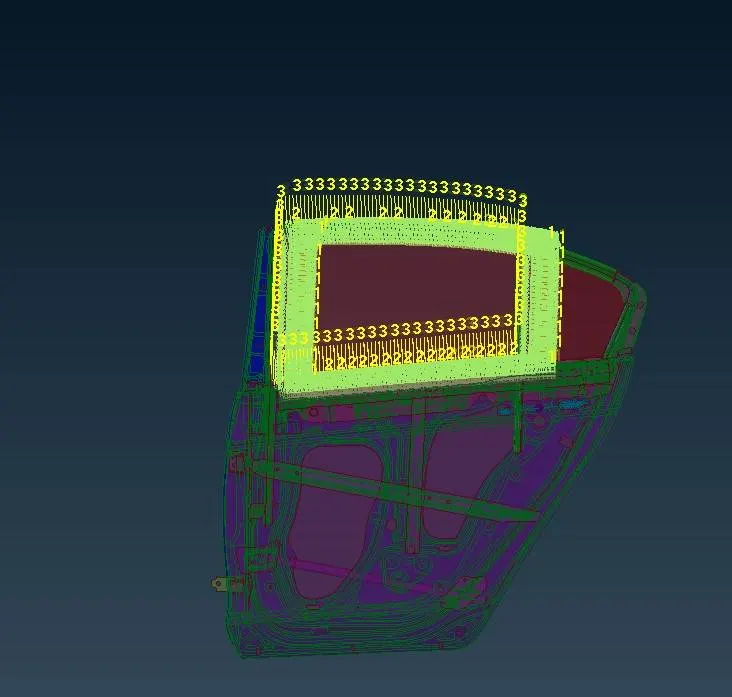
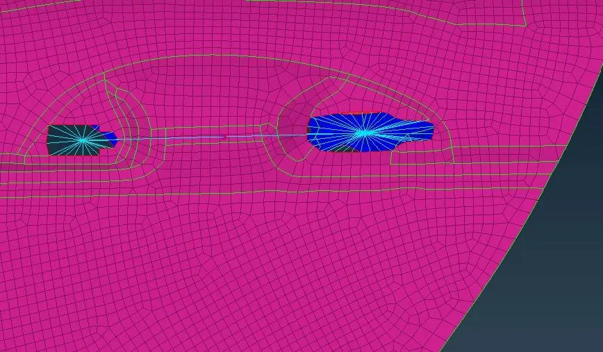
Door Handle: As the FE model of the door handle was not given however, it is required for us to consider the door handle during NVH simulation we showed the same using CONM where we entered approx. We created rigid connection at both ends and connected the master nodes using RBE3 connection with a master node at centre. Mass of the door handles and added it to centre of the connection. In this case`1e^-4` tonnes. Below is an image of the same.
Conclusion: Hereby, all required connection in the given FE model of rear door were implemented. We can say that by establishing connections at all required places the model is ready for the NVH simulation.
Learning Outcome: We learnt various type of connections like, bolts, spot weld, seam weld and got to know about FE representations of the same for. Got to learn how to use tolls like RBE2 and RBE3 in NASTRAN deck. We got to know about various aspects to be considered during designing of parts and how to prepare the parts for NVH simulation.