Week 8 Worm Gear Challenge
Objective: Perform a transient structural analysis on a worm gear assembly. cut the gear by half so as to bring the model within limits. Rotate the worm so as to get to almost the end of the half-cut and get results for Equivalent stress, Equivalent elastic strain, and the total deformation in the model.
Procedure: Start a Transient Structural analysis in ANSYS Workbench
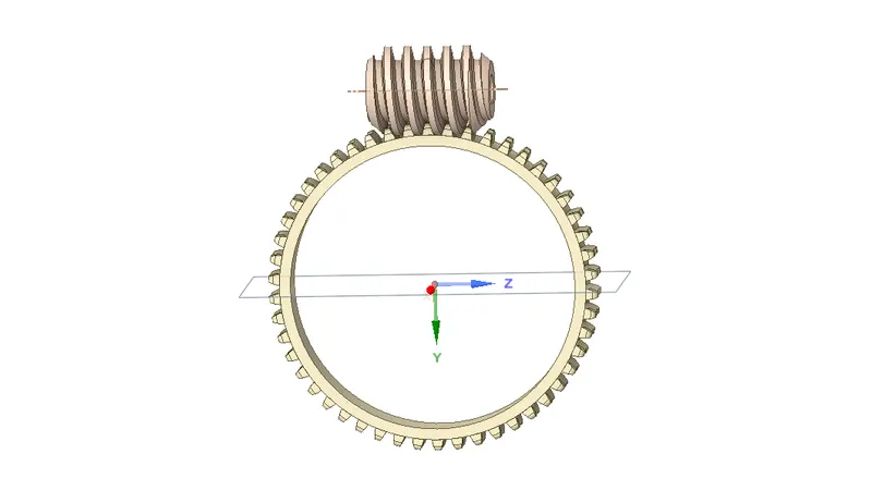
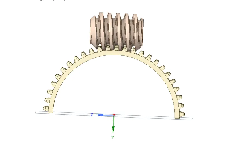
- Geometry: Import the geometry, open SpaceClaim and edit the bigger gear to cut into half, so that it can be brought under the limit of the Academic Model, the below image shows the same:
Initial:
Final:
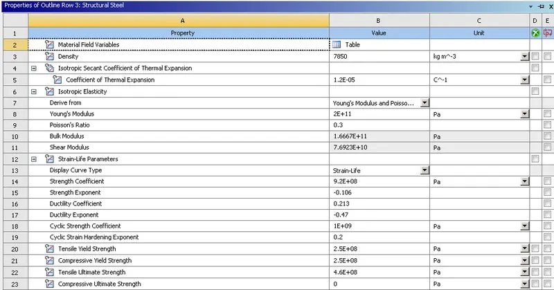
- Material: For this model, we will be using Structural Steel as material.
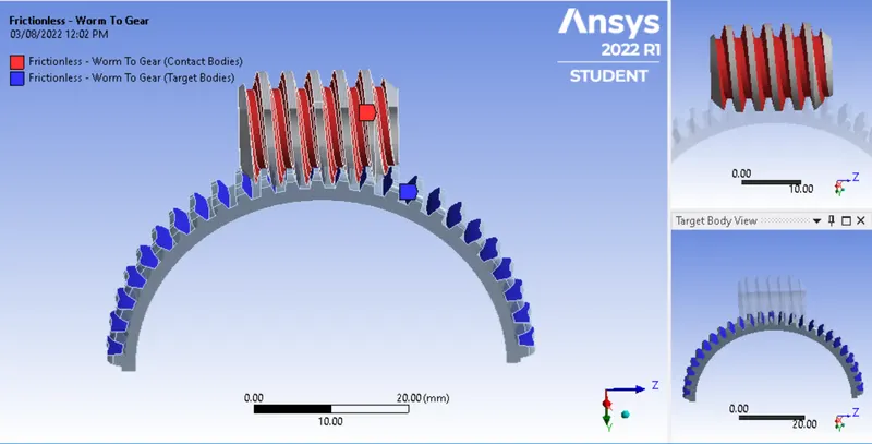
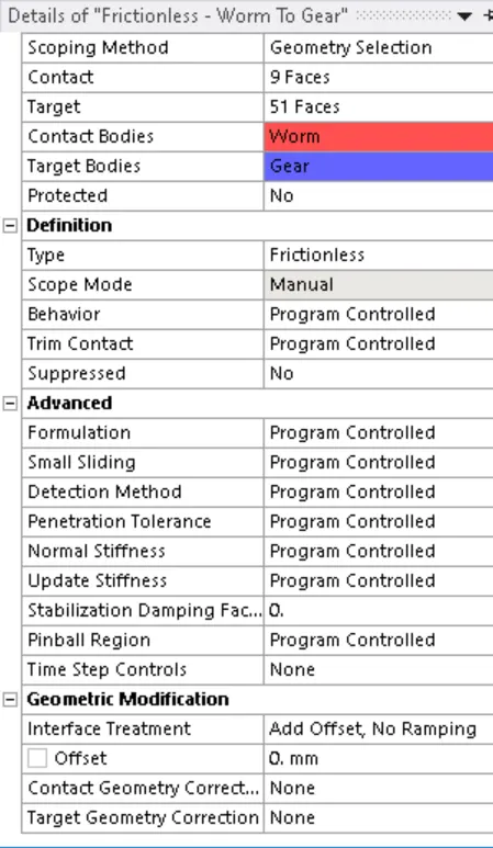
- Contacts and Joints: After assigning material, we will set a Frictionless contact between two gears. Here we will select all faces of bigger gear and worm gear as shown in the image.
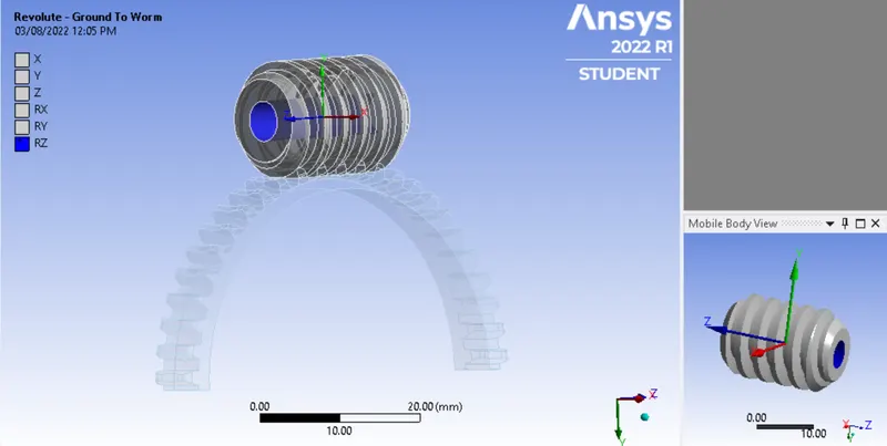
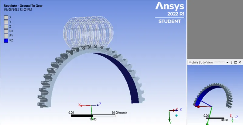
Joints: We will setup Revolute joint for worm and big gear, we will set the rotation in Z-direction, the joint type is Body-to-Ground, below image shows the same:
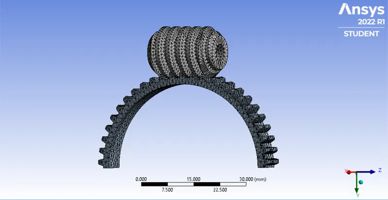
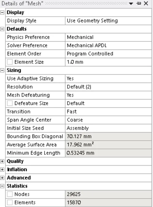
- Mesh: Here to mesh we have used a mesh size of 1mm, here we will mesh with Adaptive Sizing on and medium smoothing. Below are the image of mesh generated:
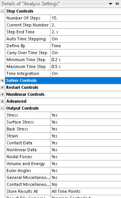
- Analysis Settings and Boundary Conditions: For this simulation, we will run the simulation for 15 steps, with a minimum and initial time step of 0.2 and maximum time step of 0.5, we will change weak springs to program-controlled, large deflection will be ON. We will turn on all options in output controls to Yes except Contact misc. below image shows the same
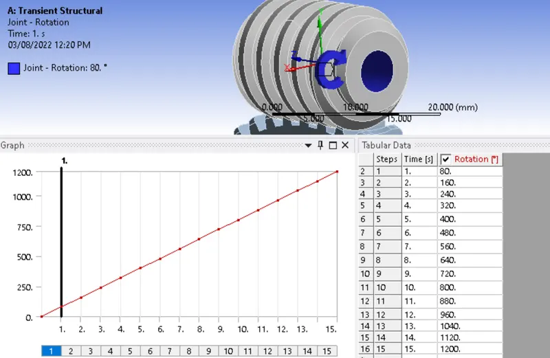
Boundary Conditions: We will add a rotation joint using the Revolute joint created for the worm gear. We will rotate the gear for 80 for each step:
- Results:
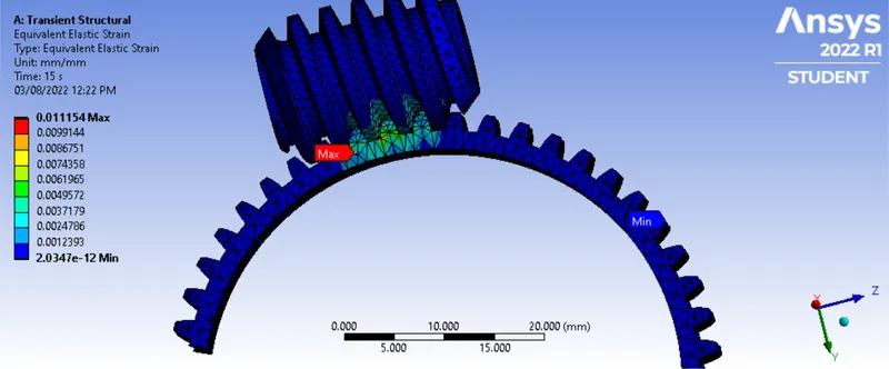
Equivalent Elastic Strain:
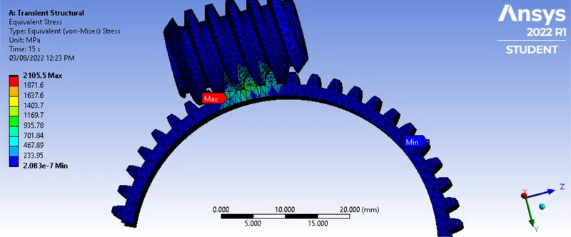
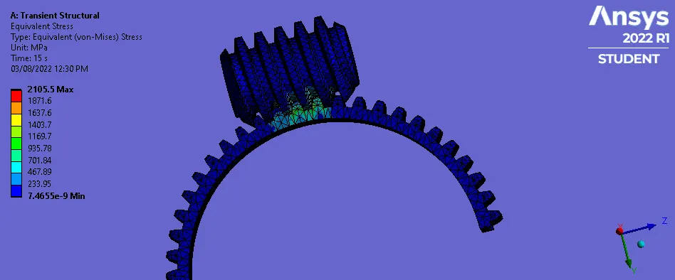
Equivalent stress:
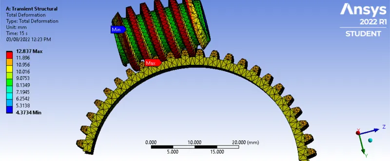
Total Deformation:
| Equivalent Elastic Strain | Equivalent Stress | Total Deformation |
| Min | Max | Min | Max | Min | Max | |
| 2.0347e-012 mm/mm | 1.1154e-002 mm/mm | 2.083e-007 MPa | 2105.5 MPa | 4.3734 mm | 12.837 mm |
- Conclusion: From the results above we can see that the maximum stress is where the teeth of both gears come in contact, the deformation is also maximum at teeth.