Week 5 Bending of iPhone
Objective: Simulate the bending of the iPhone as per the given cases below
Case 1: Simulate the model as it is given in the video
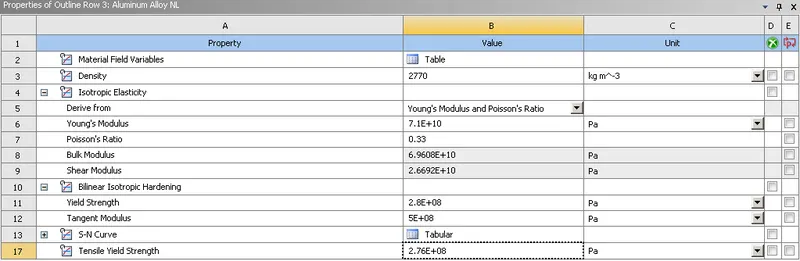
Case 2: Move the bottom fingers from their defined position to the given position X= 22.5mm & Z= 10mm and obtain the results for the simulation. Also, define the S-N curve for the Aluminium Alloy material as per values given below and determine the fatigue life results for the same.
Procedure:
- Geometry
- Adding Materials
- Contacts
- Mesh
- Analysis Setting and Boundary Conditions
- Solution
- Conclusion
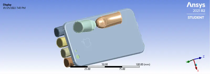
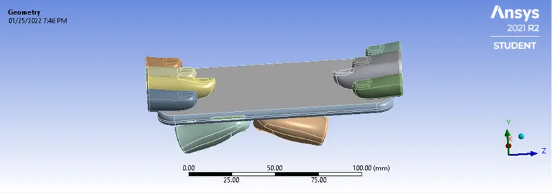
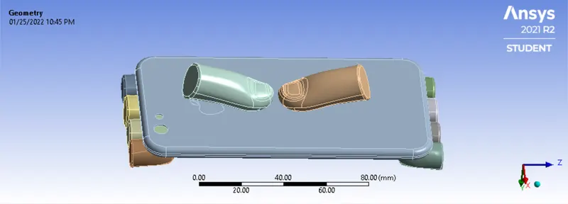
- Geometry: In the given model of an iPhone we have made certain changes for case 2 and moved a few parts, the below images show both. In case two we have moved the Pushing Fingers 22.5mm in X-Direction and 10mm Z-Direction. Upon importing we will also rename the parts.
Case 1:
Case 2:
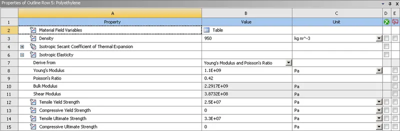
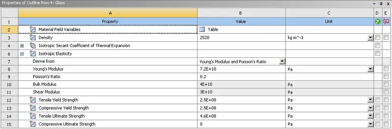
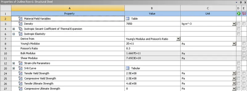
- Adding Materials: For this simulation, we have used 4 different materials. For the Display of the iPhone, we have used Glass, we have used Aluminium Alloy non-Linear for the Case(frame), Polyethene for the interior of the phone and Structural Steel to denote the fingers. The below image shows the material details:
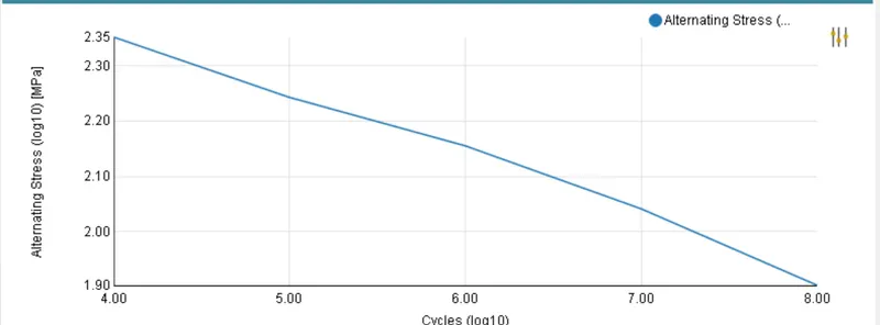
Aluminium Alloy Non-Linear with S-N Curve based on given data:
Polyethene:
Glass:
Structural Steel:
- Contacts: For establishing contacts we have been provided with contacts with the model, we will keep them and delete the contacts which are not required. We will change the contact type as Frictionless for all the contacts except for contact between display and frame we will keep it as bonded.
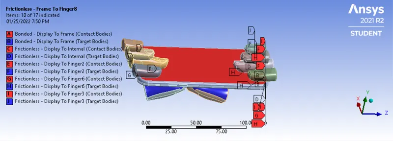
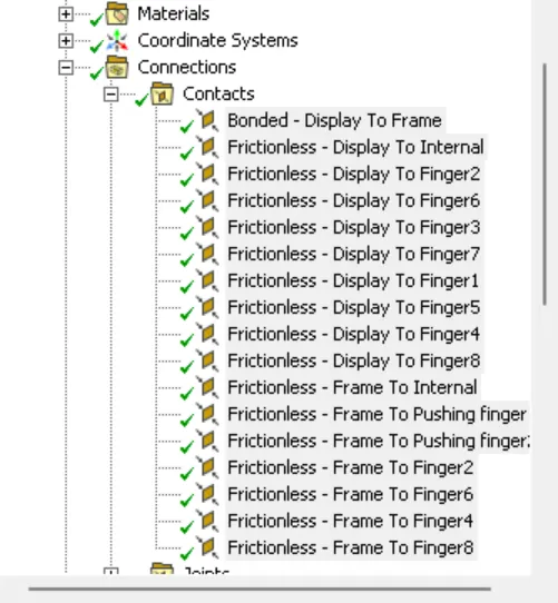
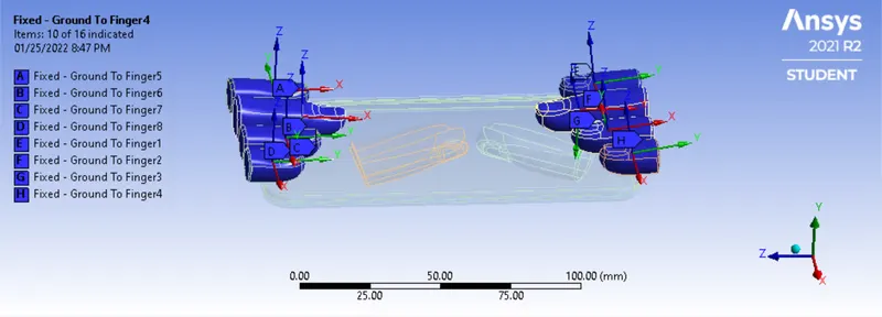
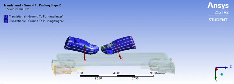
Now, to show the contact of fingers we will select each finger one by one and provide the fixed contact. And for both the Pushing Fingers we will give the translational contact and we will make sure the X coordinate for both is defined by the Global Y-Coordinate as shown in the figure:
- Mesh: For meshing, we will, first of all, create a Face Sizing and select the faces of Pushing Finger and frame as shown in the figure and give the mesh sizing of 4mm:
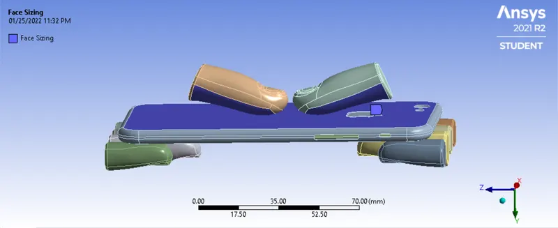
Once selected we will go Quality>Smoothing and change it to low. Once done we will go ahead to generate the mesh, the mesh generated is shown in the image below:
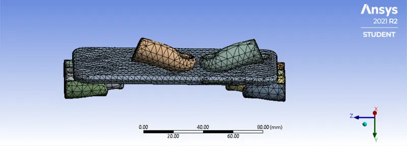
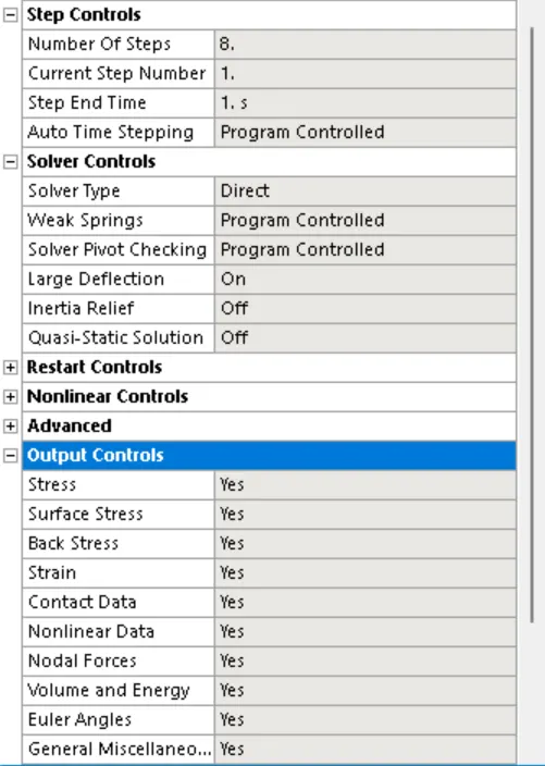
- Analysis Setting and Boundary Conditions: For this model, we will run the simulation for 8 steps. We will select all 8 steps and change the solver type as Direct and change the Weak Spring to Program Controlled, we will also turn on the Large Deflection. We will change all the options in Output Controls to Yes.
For boundary conditions, we will first select the faces of the inside as shown in the figure and give it as fixed support so that the iPhone does not fly off while the force is being applied. Also, we will select the side faces of Frame as give the displacement as 0mm is X and Z direction, while the Y-direction remains free.
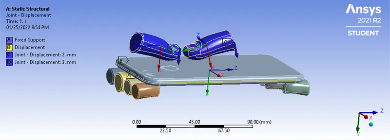
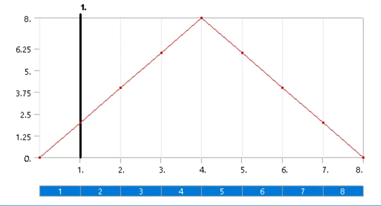
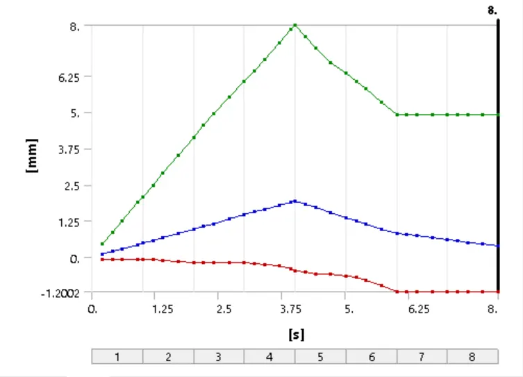
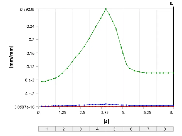
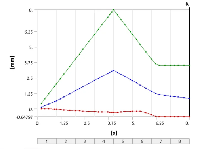
We will select the Pushing Fingers and give the joint load, with the gradual displacement of 2mm for 4 steps in the X direction and similarly, we will retract the fingers for the next 4 steps, the graph below the same.
- Solution: After entering all the contacts, mesh and boundary conditions we will run the solution, below are the results of both cases:
Case 1:
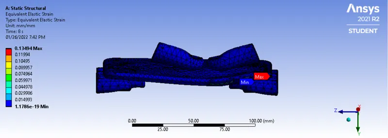
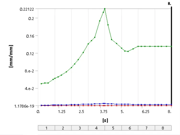
Equivalent Elastic Strain:
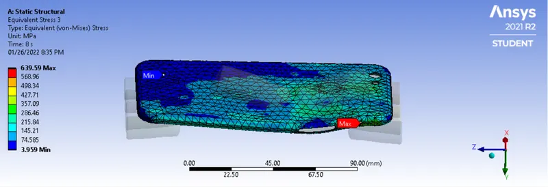
Equivalent Stress:
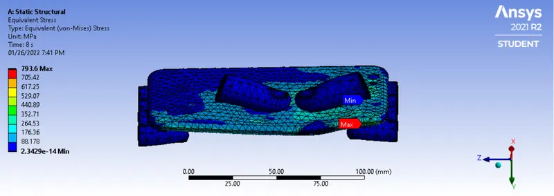
Equivalent Stress for Case:
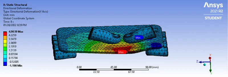
Directional Deformation in Y-Direction:
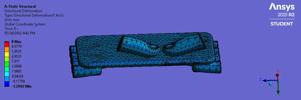
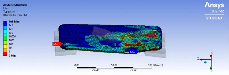
Life Cycle: The below result suggests the Min and Max life cycle of the product on the given load, we can see that where the load is applied the life cycle is min i.e. 0, as there is plastic deformation and the frame may fail at first impact. While the life cycle is Max at the regio which is far from the load application.
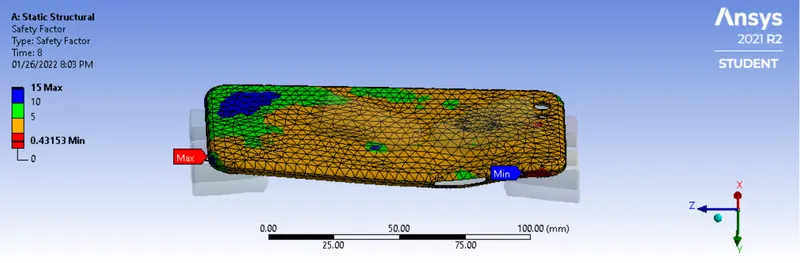
Factor of Safety: The result below shows the Factor of Safety on given load, we can see it is minimum where the load has been applied while it is maximum at the Blue region. We can confirm the same by following method:
Factor of Safety: Tensile Yield Strenght of material/Max equivalent Stress(for case) = 276/639.59 = 0.431, which is correct as shown in image below
Case 2:
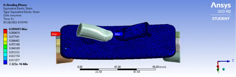
Equivalent Elastic Strain:
Equivalent Stress:
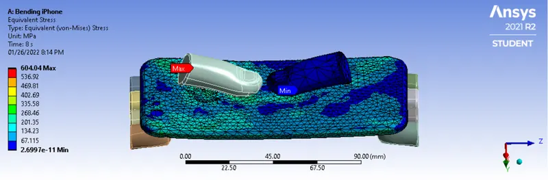
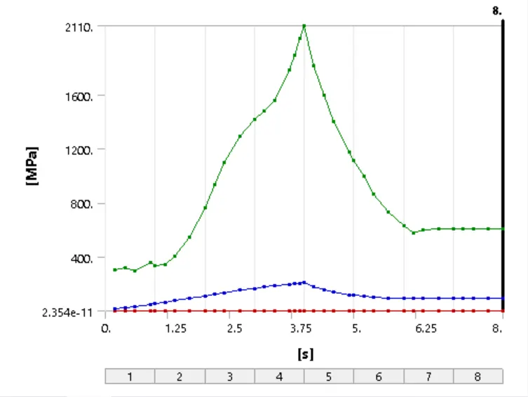
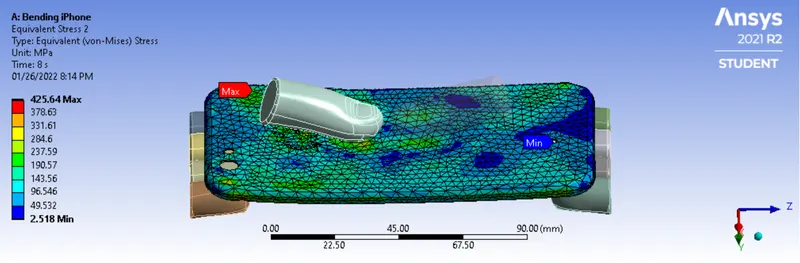
Equivalent Stress for Case:
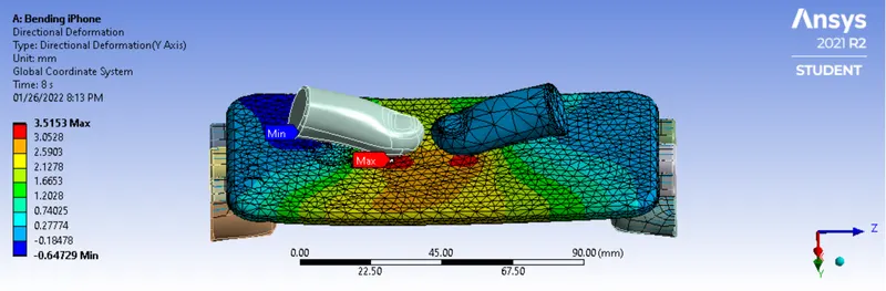
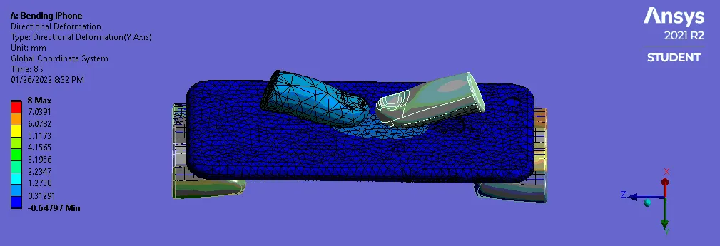
Directional Deformation in Y-Direction:
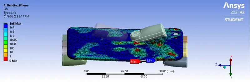
Life Cycle: The below result suggests the Min and Max life cycle of the product on the given load, we can see that where the load is applied the life cycle is min i.e. 0, as there is plastic deformation and the frame may fail at first impact. We can see that in Case 1 the Min and Max Life was at different on the model, however, as the load is applied on the center portion it is much closer in this case.
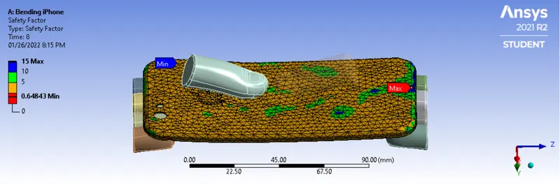
Factor of Safety: The result below shows the Factor of Safety on given load, we can see it is minimum where the load has been applied while it is maximum at the Blue region. We can confirm the same by following method:
Factor of Safety: Tensile Yield Strenght of material/Max equivalent Stress(for case) = 276/426.64 = 0.647, which is correct.
- Conclusion:
| Equivalent Elastic Strain | Equivalent Stress | Direction Deformation in Y-Axis |
| Min | Max | Min | Max | Min | Max | |
| Case 1 | 1.1786e-019 mm/mm | 0.13494 mm/mm | 2.3429e-014 MPa | 793.6 MPa | -1.198 mm | 4.7815 mm |
| Case 2 | 7.322e-016 mm/mm | 0.09969 mm/mm | 2.6997e-011 MPa | 604.4 MPa | -0.647 mm | 3.5153mm |
Based on the results of bth the cases we can say that with load being appllied applied at center portion, as in Case 2 the iPhone performed much better with better stress and strain values also, the deformation is much lesser in Case 2. We can also compare the safety factor which is much higher in Case 2. With this result we can conclude thaat the iPhone has much higher chances of failure due to impacts and load on sides of the frame.