Week 12:Project 2-Meshing of Rear Wheel Holder challenge
Objective: Mesh the Wheel Holder model. Do the geometry cleanup, mid surfacing and meshing with given quality criteria.
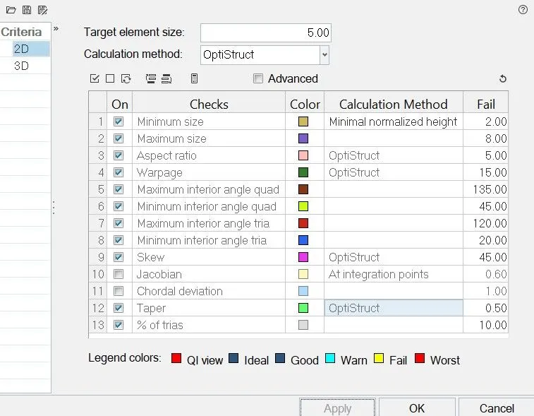
Quality Criteria:
| S.N | Quality Criteria | Value |
| 01 | Target Lenght | 5 |
| 02 | Aspect Ratio | 5 |
| 03 | Skewness | 45 |
| 04 | Warping | 15 |
| 05 | Taper | 0.5 |
| 06 | Min. Length | 2 Units |
| 07 | Max. Length | 8 Units |
| 08 | Min angle Quad | 45 |
| 09 | Max angle Quad | 135 |
| 10 | Min angle Tria | 20 |
| 11 | Max angle Tria | 120 |
| 12 | Tria % | 10 |
Procedure:
-
Import
-
Geometry Cleanup
-
Mid-surfacing
-
Defeaturing and Mid-surface cleanup
-
Meshing
-
Elemental Cleanup and Mesh improvement
-
Assigning Material, Property and Thickness
-
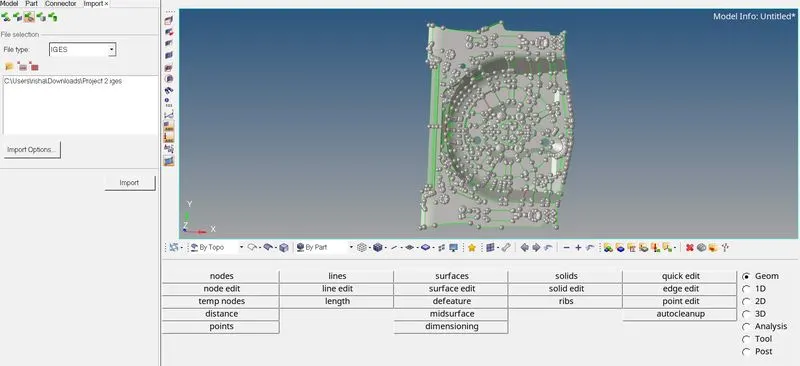
Import: The given model is in .IGES, hence we can go to Import Tool>Geometery>Import. The below image shows the same.
-
Geometry Cleanup: In order to create mid-surface with lesser surface issues, we need clear the issues with the Parent Geometry: After importing we will check the complete model for such issues and resolve the same.
We can change the view to wire-frame to see free edges in parent geometry. The wire-frame view for parent geometry must not have any free edges. The below image shows the issue with parent geometry.
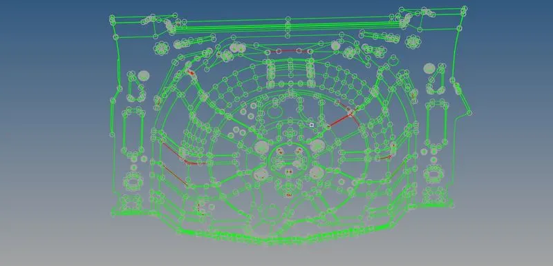
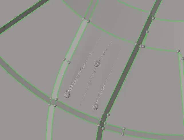
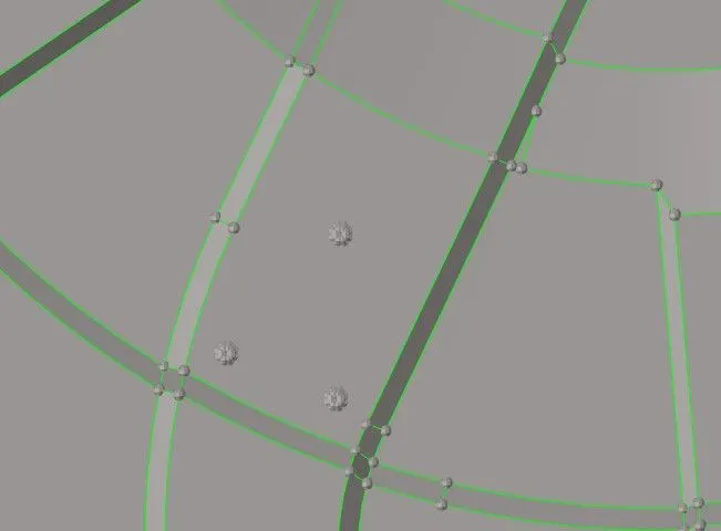
The below image shows the issues with the surface, we can fix them deleting the surface with issue and create a new surface using Geom>Surface>Ruled.
Surface Issue Fixed Surface
-
Mid-surfacing: After clearing the issues with the geometry we can create the mid-surface. For the given model since the thickness is inform throughout the geometry, we can use Auto-Mid option to create mid-surface.
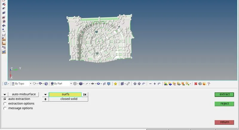
For auto-mid we go to Geom>Mid-surface>Auto Mid-surface. For extraction option we tried different option and check given best result, hence for this model we used Offset+Plane+Sweep. The surface so created will be assigned to another component created for mid-surface.
The below image shows the procedure of extracting the mid-surface.
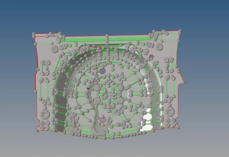
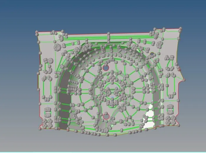
Below image shows the midsurface generated.
-
De-featuring and Mid-surface cleanup: Once the mid-surface is created we have to work on it to resolve the issue related to the surface as well do the defeaturing.
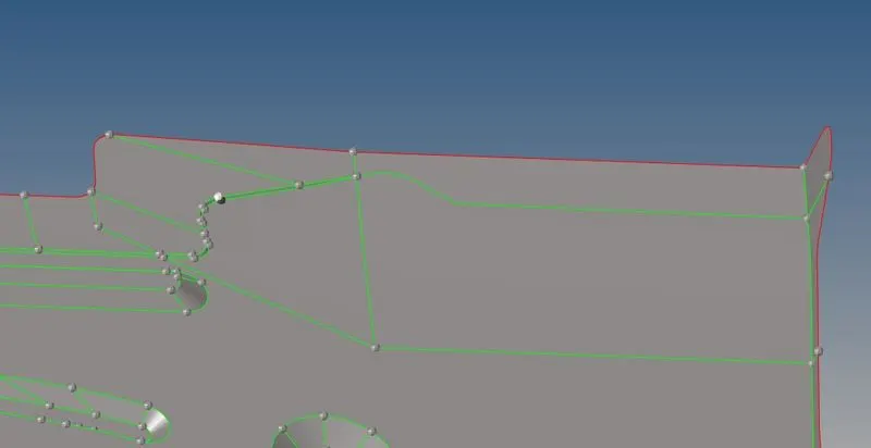
For de-featuring we will toggles the lines that can cause the elements to fail for minimum length.
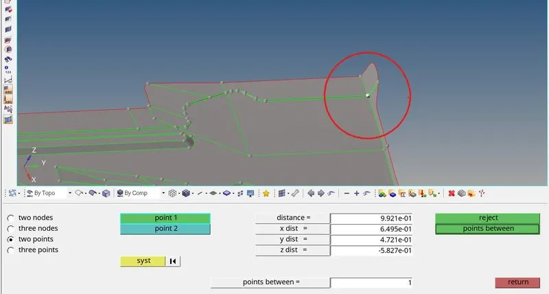
We can toggle lines using Geom>Quick Edit>Toggle. We can also replace nodes option to from Qucik Edit tools. The below image shows one example.
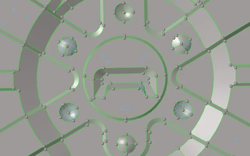
Now for feature which may result in poor mesh flow, we either defeature it, or if the feature is too small we can remove it and fill the surface. Below image shows parts we have defeature for better mesh flow and feature capturing.
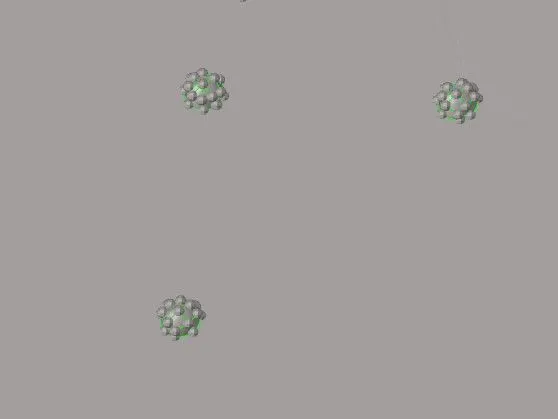
The below image shows beads which we have removed using using Delete Surface and created new surface there to fill the holes.
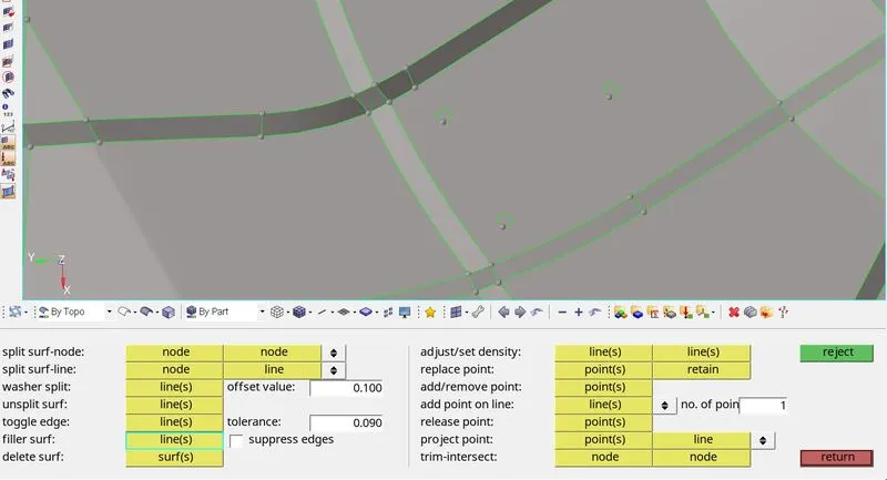
We will check for free edges and resolve the issues with the midsurface, below image shows issue with surface before and after they are fixed.
The below image shows the free surfaces which have to be fixed
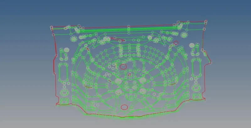
The below image shows the final midsurface after fixing all the issues.
-
Meshing: Once the mid-surface is created we can proceed to mesh the model. Before meshing we will import the mesh criteria. The below image shows the same.
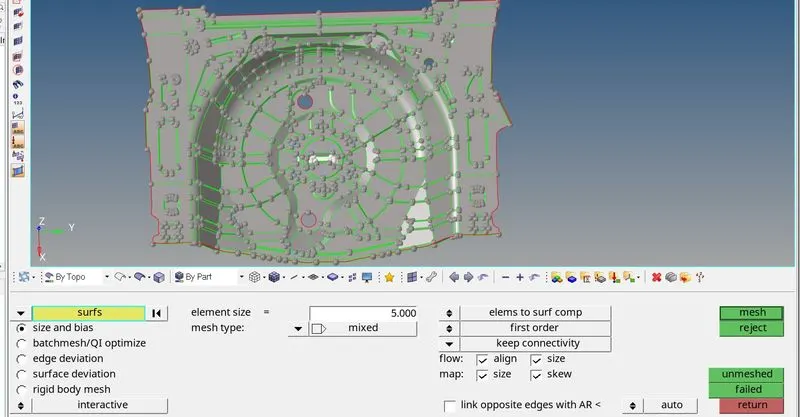
For meshing we will use 2D>Automesh option. We will select each surface individually and mesh them. For such model we start to mesh from center and progressively go outwards. The procedure to mesh is shows in below.
-
Elemental Cleanup and Mesh improvement: For the given model we resolved the off elements as we proceeded. For resolving the off elements we used 2D>Quality Criteria>Cleanup Tools. The below image shows the example of elements.
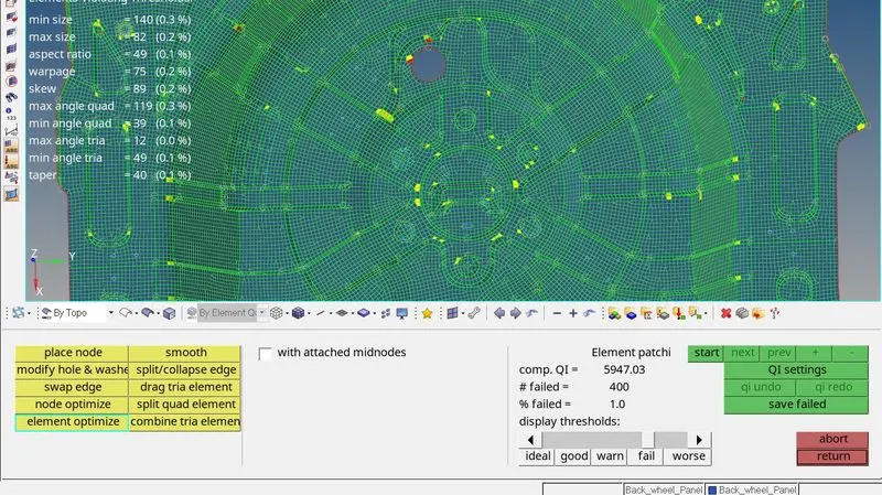
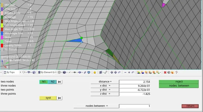
For features like one shown in the image we have to decide whether to capture the feature or maintain elemental quality. Here we have slightly varied from the feature and also removed few elements to have no failing elements. We have removed elements which were failing for minimum length by replacing nodes. The below image shows before and after correction.
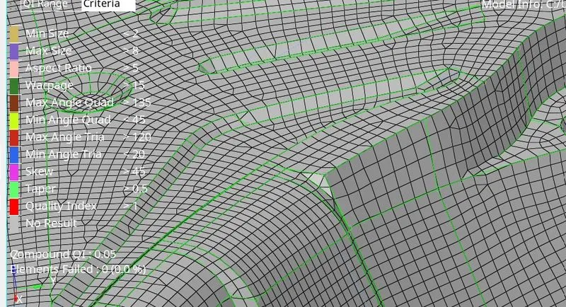
Once the off elements are removed we need to work on mesh to improve the flow. In order to improve we can use 2D>Smooth>Size Corrected tool.
Also, we need to work on mesh to reduce tria concentration. For that we can remove opposite trias. After meshing the tria percentage in model was 4.2%, however, as per model we are required to bring it down below 3%. The below image shows opposite tria which can be removed by connecting the two trias and making a quad and which can be combined using Quality Criteria>Drag Tria and Combine Trai elem.
We also have to check for free edges between elements, to check that we will go to Tools>Edges>Elements>Find edges. Edges so found can be corrected using Equivalence tool or by Replace Nodes. The below image shows the procedure to check free edges.

Similarly we will check for Duplicate elements and Elements with connectivity issue using Tools>Check Elems. Below image shows the same.
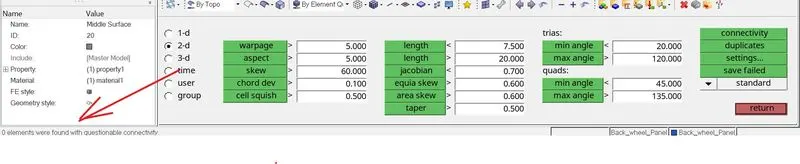
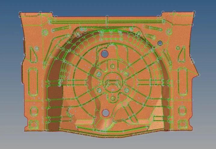
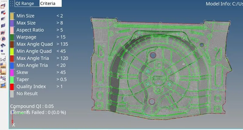
The below image shows the final mesh without any issues of failing elements.
-
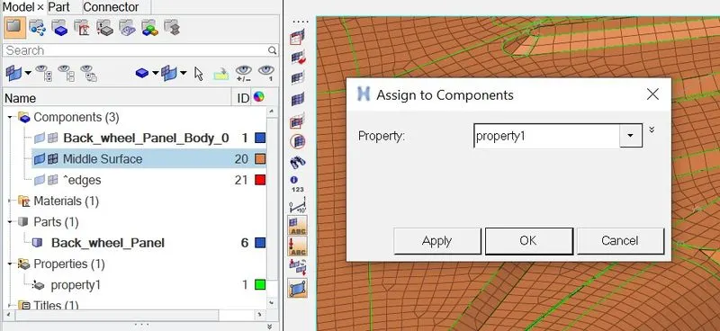
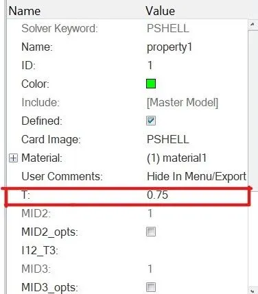
Assigning Material, Property and Thickness: Once the meshing is done we can assign the material and property to the component. For assigning thickness we can open property browser and enter thickness of parent component in T. The given component’s thickness is 0.75mm, the below image shows the same. We can apply the property and material to mid-surface component by right clicking on component and then applying.
- Final Result: Here by we have created mid-surface and meshed the given model. Hence by completing this model we learned ways to create mid-surface and meshing of the model.The blow is final image of the model.
l