Week 7-Long Piston With Cam
Objective: Perform a transient analysis on a piston and cam mechanism model that has been provided to you. You need to run the analysis with Frictionless contact, Frictional with 0.1 and 0.2 as the frictional contact for a total of 3 cases. Find out the Equivalent Stress, Directional Deformation, and Equivalent Elastic Strain and compare them for all three cases. Give an inference as to why the results vary between cases.
Procedure:
- Importing and Checking Geometry
- Material Assigning
- Contacts
- Meshing
- Analysis Settings
- Results
- Conclusion
Start a transient Structural Analysis in Ansys Workbench
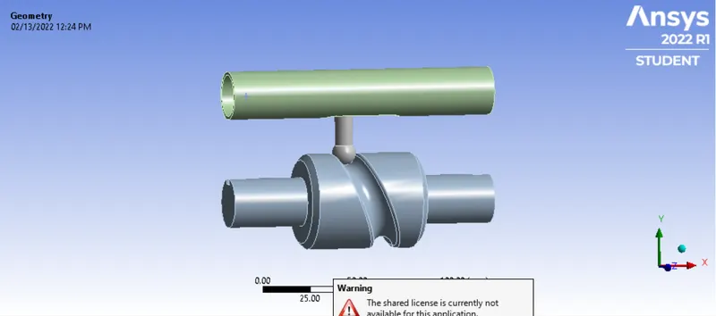
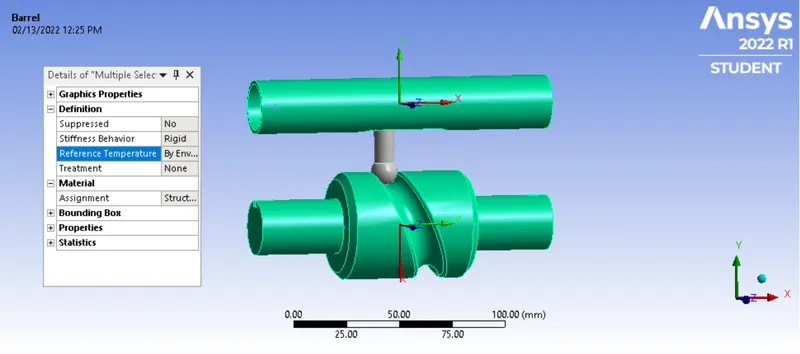
- Importing and Checking Geometry: Import the given model into the Ansys Workbench and check it in Spaceclaim for any issue. Once verified open the Mech Module. Here rename the names of the components. Change the stiffness Behaviour to Rigid for Cam and Barrel. The below images shows the same:
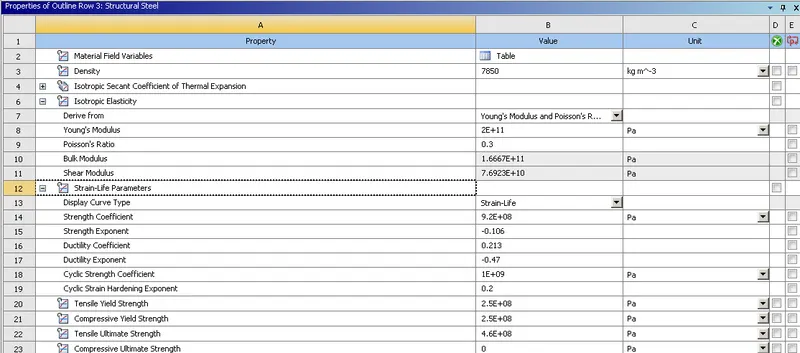
- Material Assigning: For this model use Structural Steel as material, and assign for all three components:
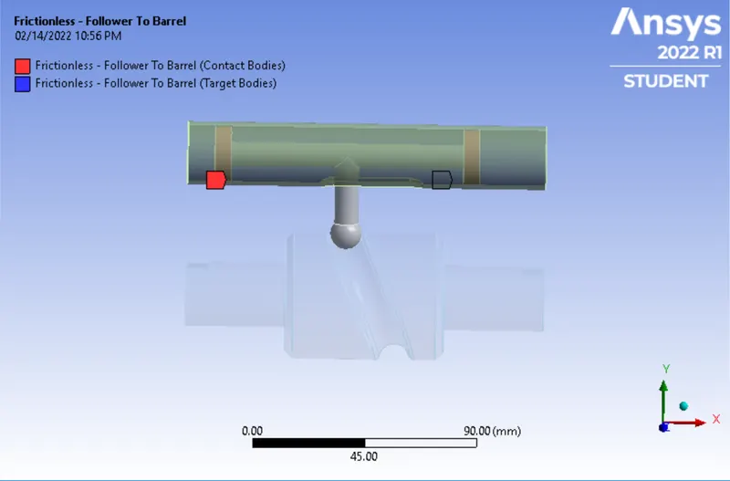
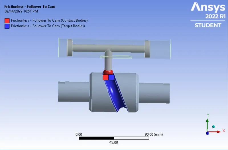
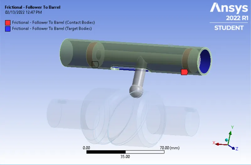
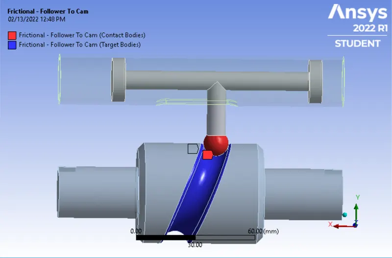
- Contacts: Here for three different cases use different types of contact, for the first case use frictionless contact, and the second third case use Friction contact with co-efficient of friction as 0.1 and 0.2 respectively. The below images shows the same:
Frictionless Contact:
Frictional Contacts:
Joints:
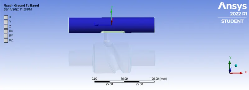
Fixed Joint: Use Body-Ground joint and fix the barrel.
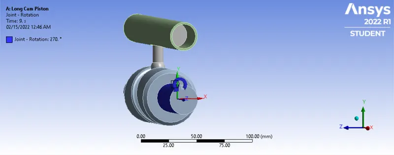
Revolute Joint: The cam barrel will rotate along the Z direction and which will result in the move of follower and piston,
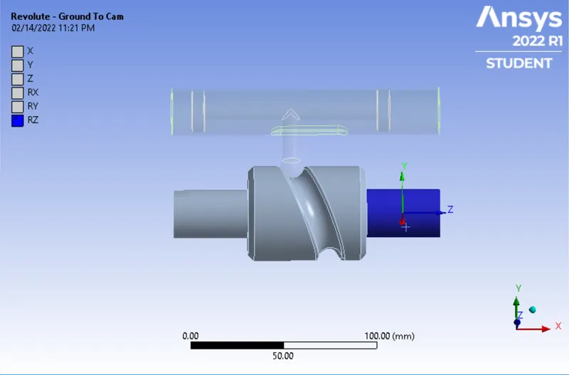
Translational Joint: We will use the translational joint to denote the conversion of rotation movement of cam to linear movement of the piston, use the Body-Body joint, select the barrel as reference body and follower face mobile body, below image shows the same: 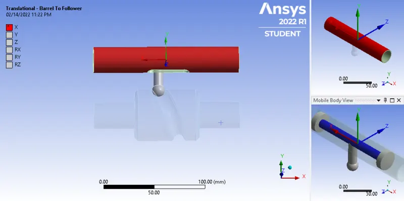
- Meshing: For this model, we will mesh the area which is going to face larger stress with face meshing, the below image shows the faces used for face meshing and the final mesh:
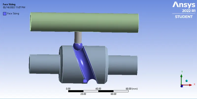
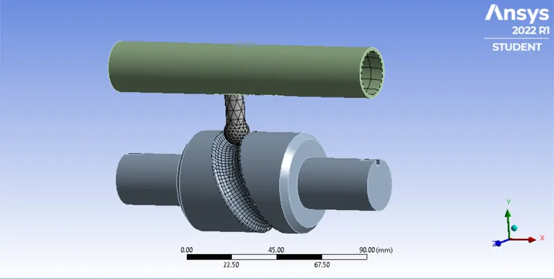
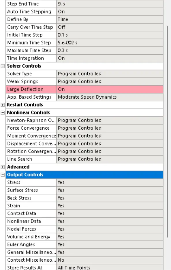
- Analysis Settings and Boundary Conditions: Run this simulation for 9 steps, enter the time steps as shown in the figure, change all options in Nonlinear controls to Programme Controlled, also change all the Options in Output Controls to Yes except the Miscellaneous Contact, the below image show the same:
Rotational Joint: Select the revolute joint and enter the degree of rotation with tabular data, the below image shows the same:
- Results:
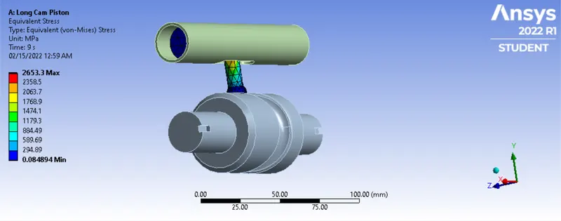
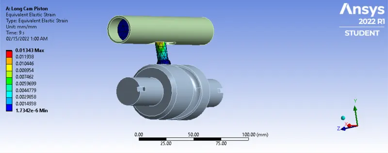
Case1: Frictionless
Equivalent Stress:
Equivalent Elastic Strain:
Directional Deformation:
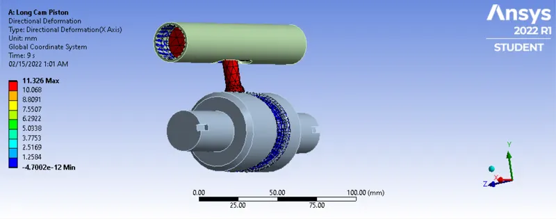
Case 2: Frictional Coefficient of 0.1
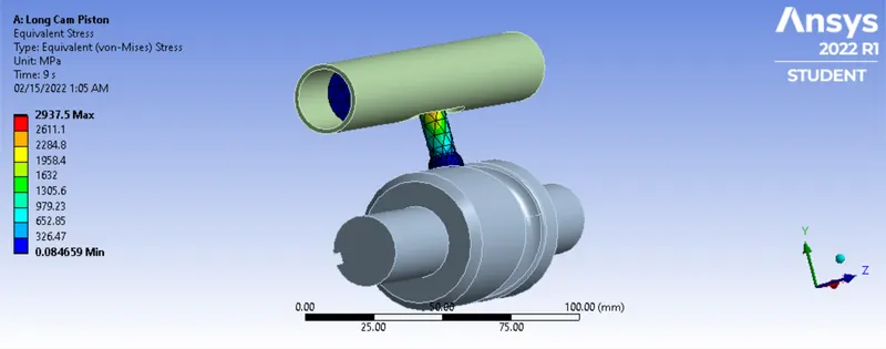
Equivalent Stress:
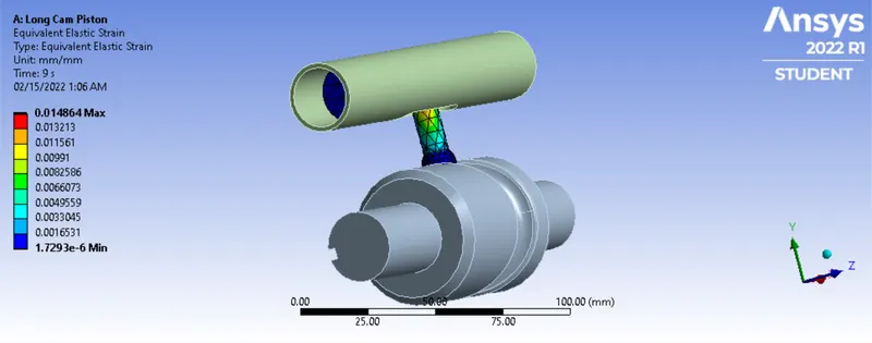
Equivalent Elastic Strain:
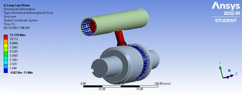
Directional Deformation:
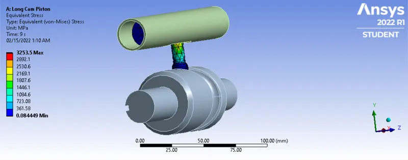
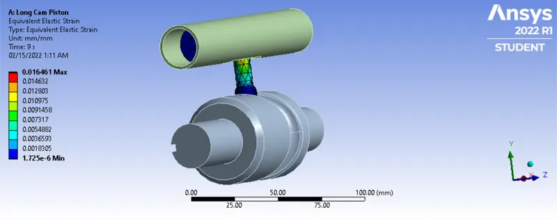
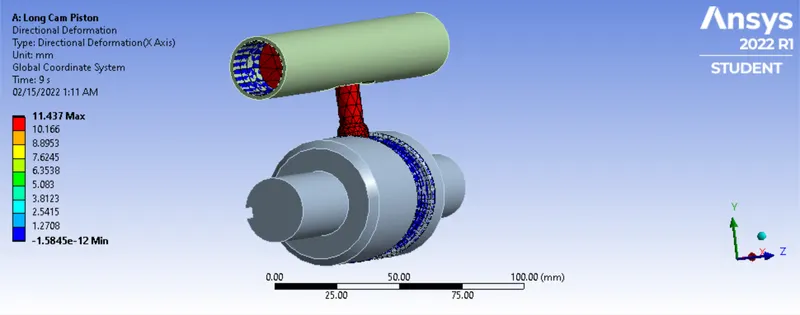
Case 3: Frictional Coefficient of 0.2
Equivalent Stress:
Equivalent Elastic Strain:
Directional Deformation:
- Conclusion:
| Frictionless | Frictional Coefficient of 0.1 |
Frictional Coefficient of 0.2 |
| Min | Max | Min | Max | Min | Max | |
| Equivalent Stress | 8.498e-002 MPa |
2653.3 MPa | 8.4659e-002 MPa |
2937.5 MPa | 8.4449e-002 MPa |
3253.5 MPa |
| Equivalent Elastic Strain | 1.734e-006 mm/mm |
1.343e-002 mm/mm |
1.729e-006 mm/mm |
1.4864e-002 mm/mm |
1.725e-006 mm/mm |
1.6461e-002 mm/mm |
| Directional Deformation | -4.7002e-012 mm |
11.326 mm | -9.8236e-011 mm |
11.376 mm | -1.5845e-012 mm |
11.437 mm |
From the results above we can conclude that with higher friction the stresses developed are more, this highest, Equivalent Stress, Strain and Directional Deformation can be seen in Case 3. Hence, it is always desirable to keep the friction as low as possible between mechanical components in contacts, it can be achieved with help of better machining of materials and periodic lubrication of the system.