Week 2 Bevel Gear Challenge
Objective: Write a few words on what a grid dependency test is and its use.
On the given Bevel Gear Model:
- Perform a grid dependency test for the Bevel gear simulation for mesh sizes of 6,5 and 4 mm
- Solve for Von-Mises stress, Equivalent elastic strain, and Total Deformation using the previously mentioned mesh sizes.
- Present your findings in an organized manner.
Answer:
Grid Dependency: It means the computation of solution on a continuously finer mesh. It is also known as Mesh Convergence Study. The purpose to perform this test is to identify the optimum size of mesh for the solution.
A high-density mesh will provide a result with more accuracy however, it will take a lot of computing power and will consume more time as well. Coarse mesh creates a significant spatial discretization error, thereby reducing the accuracy of analysis results. The test is performed to find an optimum that has the smallest number of mesh elements without generating a difference in the numerical results based on the evaluation of various grid conditions.
Below is a graph showing analysis on a simple rectangular model, the X-axis indicates numbers of mesh elements and the Y-axis indicates analysis results, here deformation was checked.
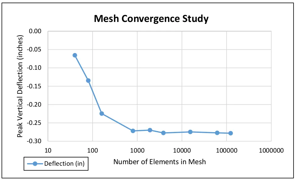
From the graph, it can be seen that with an increase in mesh size the analysis results were more consistent, we can see that with 5000-8000 elements we were able to get accurate results, which are similar to what we achieved with 100000 elements. Since the higher number of elements will require more time to compute the resolution, we can select mesh size around 5000-8000 and run the solution.
Grid Dependency Test on Bevel Gear:
As per requirement, we will run the test for three mesh sizes 6mm, 5mm, and 4mm. And we will compare the results of each case.
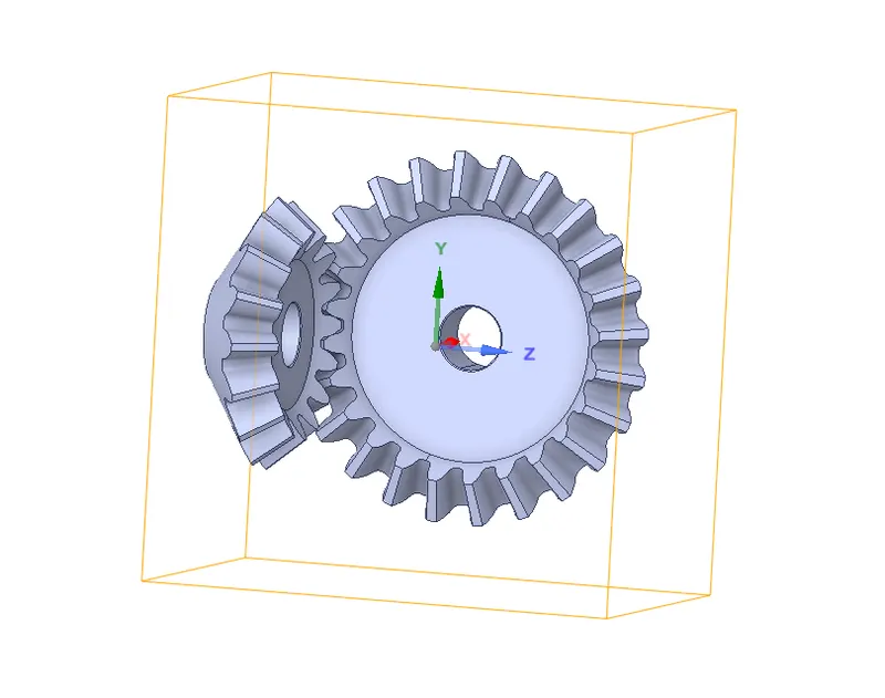
Setup: First we will open the ANSYS Workbench and start a new analysis of Static Structural. We will import the given model. The given model is of Bevel Gear with the hub, and since we do not need that we will edit the geometry to remove the hub portion. The below image shows the before and after image of editing the geometry:
Before After
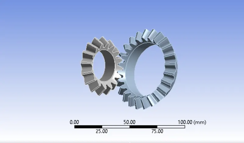
Once the geometry is edited we can proceed with the setup, we will first rename both the gears. And for this model, we have used Structural Steel as material.
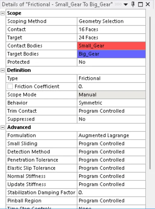
We will set up the contacts, the contact type here will be Frictional. We will select all the teeth faces that will be in contact for both gears. We will select Augmented Lagrange for the formulation method and for behavior. we will select Symmetrical
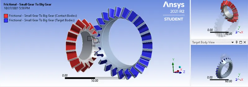
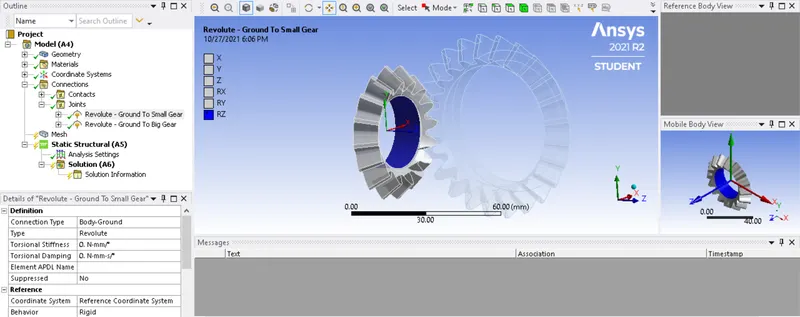
Once the contact setup is done, we will enter joints. Here the type will be revolute. The below image shows the same:
We will complete the Analysis settings. Here we will divide the analysis into 6 steps. We will enable Auto-Time Stepping and define by time. For the initial time step we will select 0.2s. We will insert the loads for the big gear we will have the moment of 100N.mm and small gear rotation of 120 degrees divided into 6 steps. We will ensure each gear has rotation in opposite direction. Once done we will enter the required solutions and run the solution.
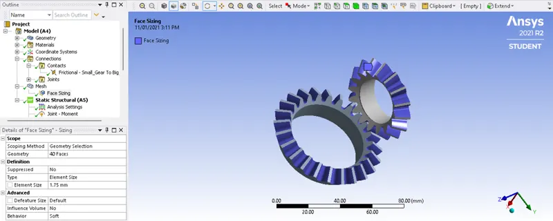
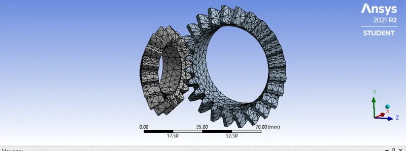
We will edit the mesh for tooth faces and provide different mesh size for it, we will select all the tooth faces of both the gears and provide them and mesh size of 1.75mm. The below image shows the same
Results:
Case 1: 6mm
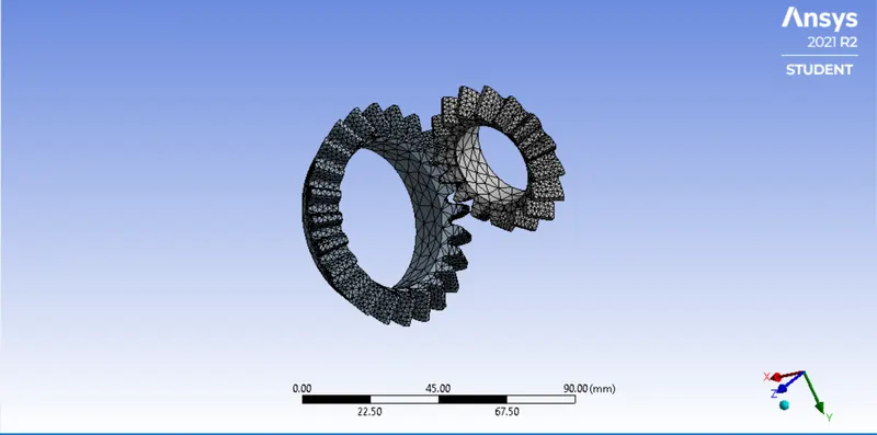
- Mesh 6mm:
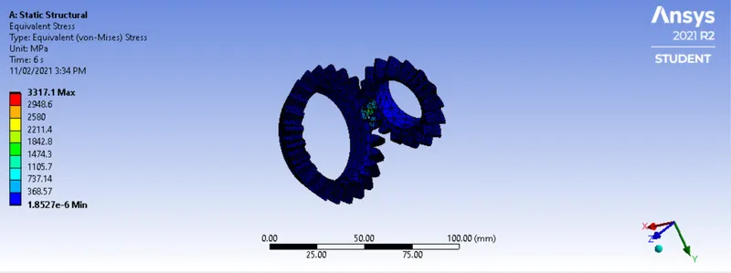
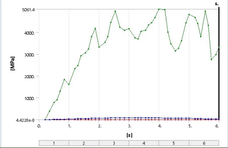
- Von-Mises Stress:
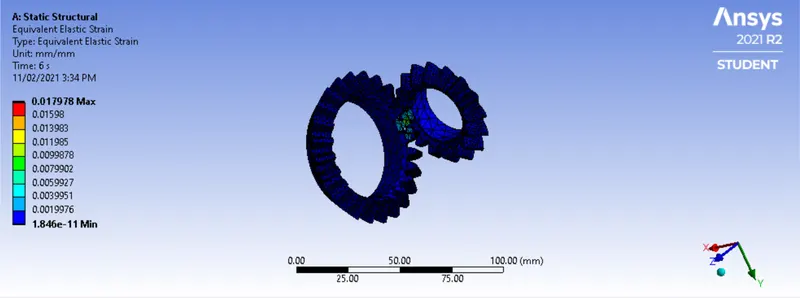
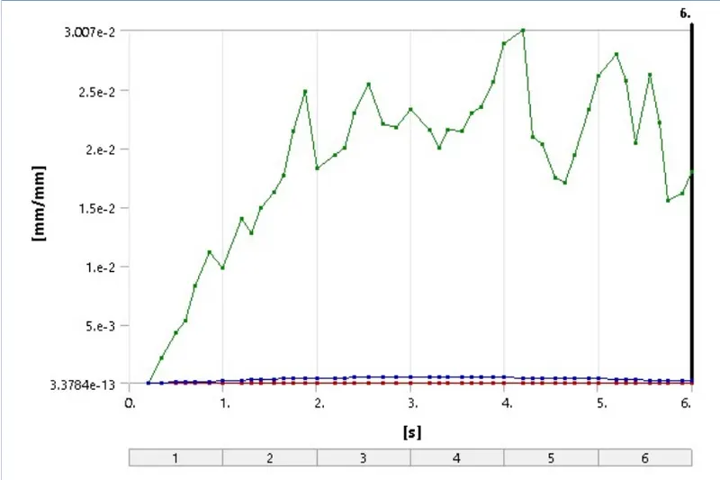
- Equivalent Strain:
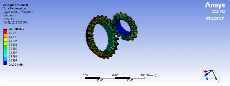
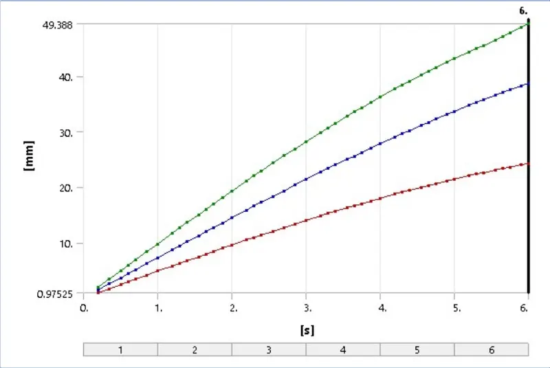
- Total Deformation:
Case 2: 5mm
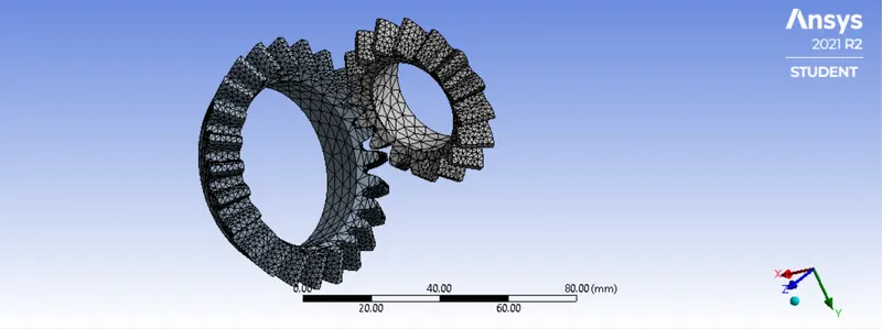
- Mesh:
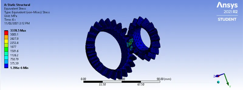
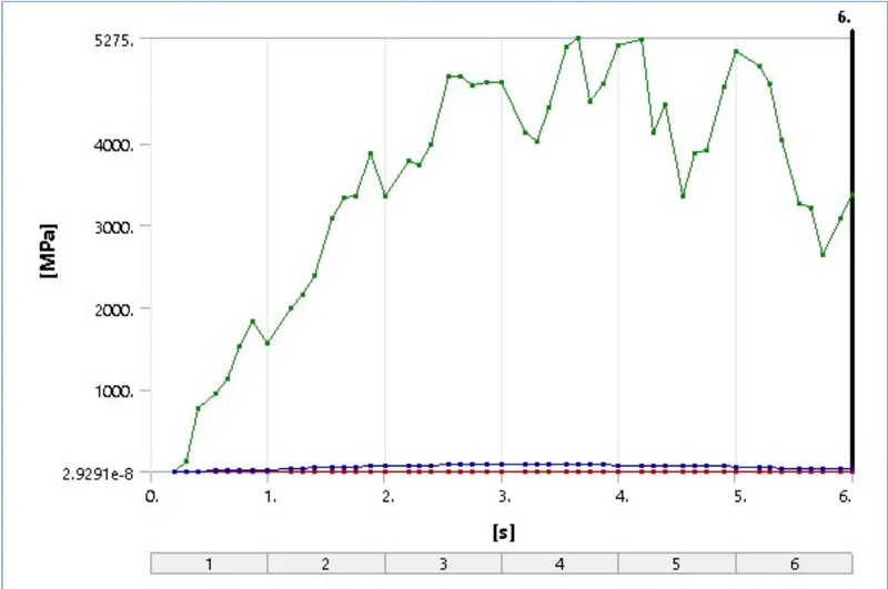
- Von-Mises Stress:
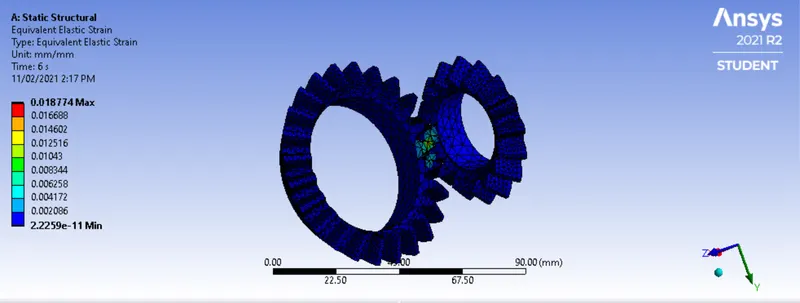
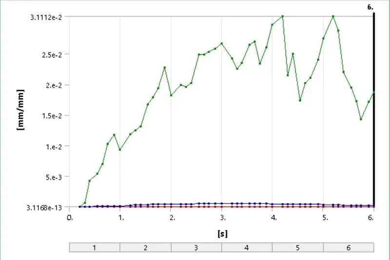
- Equivalent Strain:
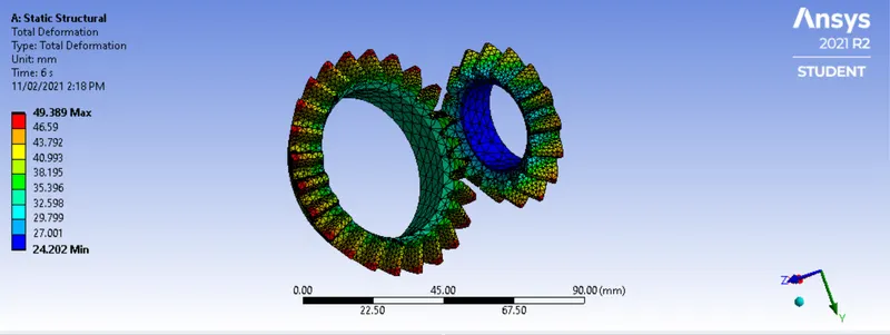
- Total Deformation:
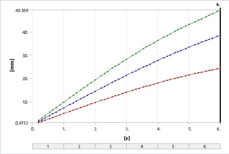
Case 3: 4mm
- Mesh:
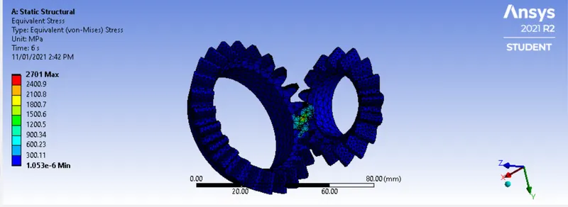
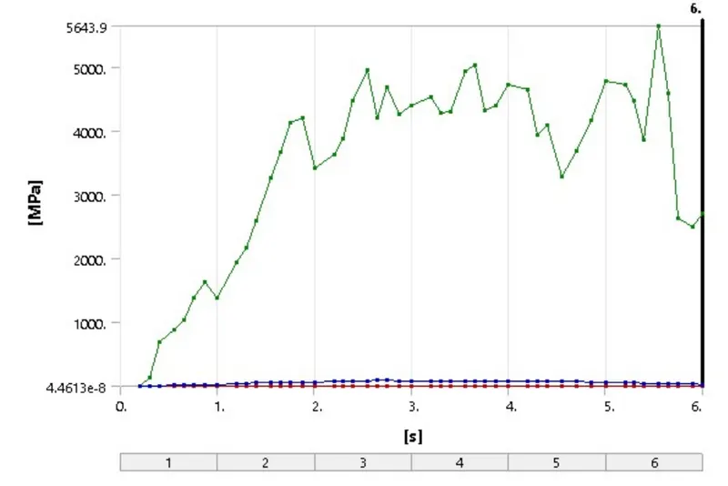
- Von-Mises Stress:
- Equivalent Strain:
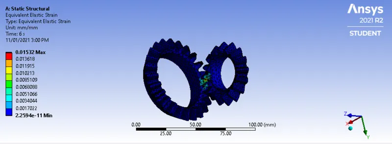
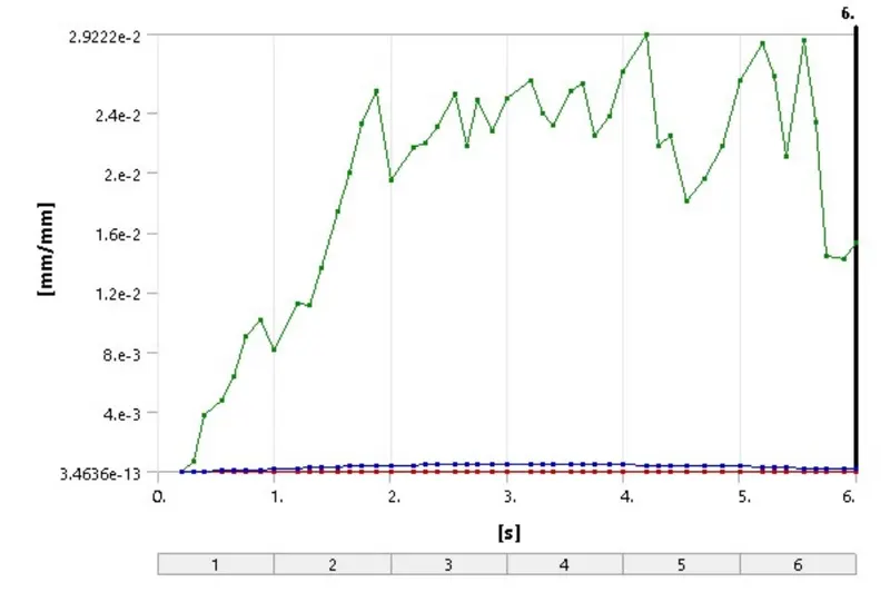
- Total deformation:
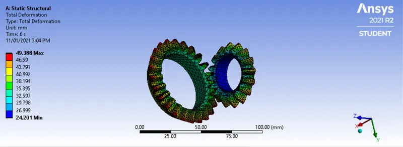
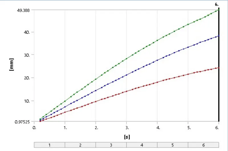
Conclusion: Below table shows the results obtained from the analysis:
| Mesh Size | Von-Mises Stress | Equivalent Strain | Deformation |
| 6mm | 3317MPa | 0.0179mm/mm | 49.38mm |
| 5mm | 3378MPa | 0.018mm/mm | 49.38mm |
| 4mm | 2701MPa | 0.015mm/mm | 49.38mm |
From the above results, we can see that between 6mm and 5mm mesh the results values for Von-Mises Stress are almost similar also the difference for Equivalent Strain is negligible.
The deformation in all three cases is similar which is 49.28mm.
Here we can conclude that going with 5mm mesh will give us optimum mesh as the results do not converge much, however, at 4mm mesh big difference is seen in Stress and Strain values. With 5mm mesh, the computation time is not as high as 6mm nor the results converge as seen in 4mm mesh.