Week 9-Creation of Connectors Challenge using Hypermesh
Objective: For this challenge, you will have to mesh the given geometry. Provided below are the quality parameters that you have to follow. And apply connections as per reuirements.
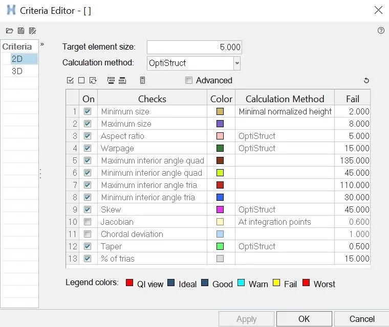
Quality Criteria: Target Lenght: 5
|
Procedure:
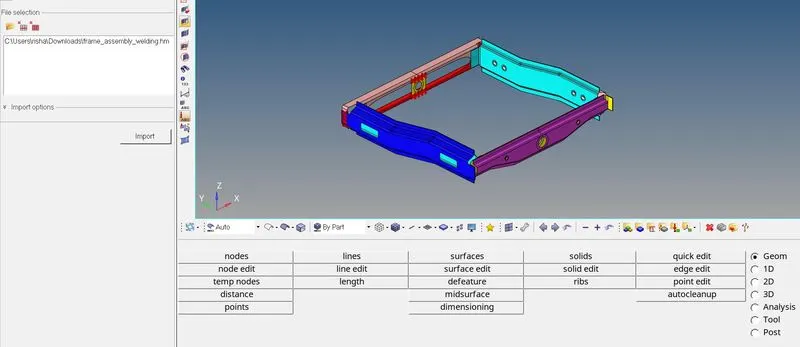
- Import:The given model is .HM format hence to import we used import tool. Import>Model. The below image shows the same.
- Meshing: In order to mesh we will first enter the given quality criteria in the system. To do we will go to Preference>Quality Criteria. The bwlo image shows the same.
In order to mesh, we will use Surface, we will isolate each surface and mesh them. The setup for same is shown below.

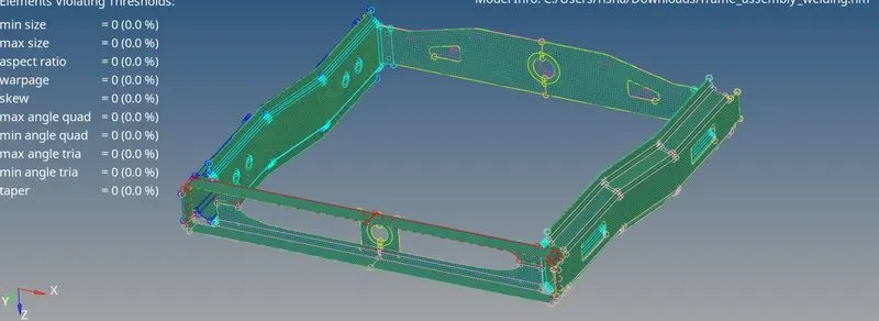
Once meshing is done we will check for failing elements by Quality Index and correct them using different tolls we will remove the off elements. The below image shpws the meshed model after all issues are resolved.
Connections: In order to check and access all connectors we will firt enable Connector tab from View>Browser>Hypermesh.Connector
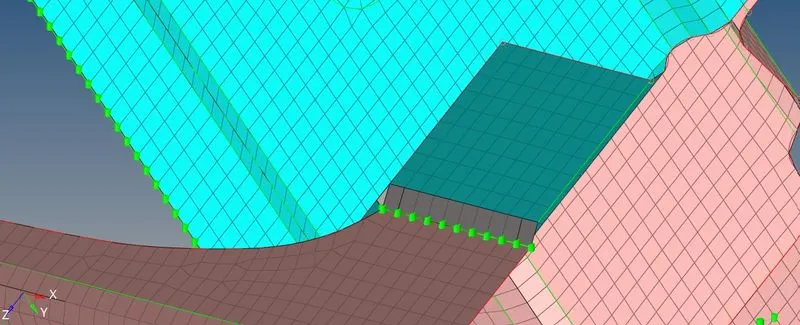
- 1st - Right_Rail_2 & Front_truss_1:- Seam-Quad(angled+capped+L): In order to make seam weld connection as per requirement we will first isolate the componenets to be connected.Then we will go to 2d>connector>Seam. Now we will select weld type as Seam-Quad(angled+capped+L).

In order to create connection we will select node path at one component. Then select both components, and provide search tolerance enough as both connections are included. We will keep spacing to match the element size. We will keep weld angle as 60 degree and cap angle as 70, it has to be slected in a way that it does not exceed the elements. The below image shows the result. The greeen nodes suggests that connection are relaised successfully.
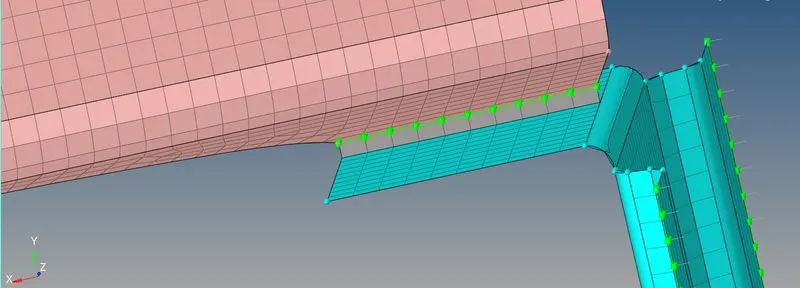
- 2nd- Left_Rail_2 & Front_truss_1:- Quad elements: In order to create quad connection we will first isole the two components that are Left Rail2 and Front Truss 1. Same as before we will go to 2d>connector>Seam and select Quads as type.

We will sleect node path, give spacng and tolerance same as earlier. We used imprint to so that mesh in two doifferent components can be aligned. Below image shows the same.
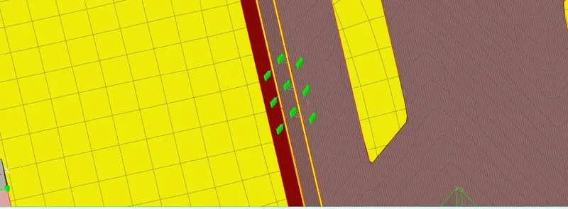
- 3rd- Front_truss_2, Front_truss_1 & Right_Rail_1:- Spot weld with 2 Layers and 5 mm Diameter: In order to create connection we will first isolate the two components. We will the go to 2d>Connectors>Spot we will keep the type as Plot. The below image shows the setup.

Simiarly as before we will give node list and give spacing to match element size and select two components. Give diameter as mentioned and create connection. Since three component wwere given and 2 layer were to be slected we have to repeat the process once to get all components connected.
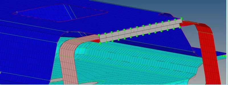
- 4th- Front_truss_2, Front_truss_1 & Left_Rail_1:- Hexa (Adhesive): To make seam weld connection as per requirement we will first isolate the componenets to be connected.Then we will go to 2d>connector>Seam. Now we will select weld type as Hexa(Adhesive Contact).

imiarly as before we will give node list and give spacing to match element size and select two components. Here we have to select width, strips and coats as per requirement. Since three component were give, we have to repeat the process once to get all components connected. The below image shows the results. The green nodes suggests realised connections.
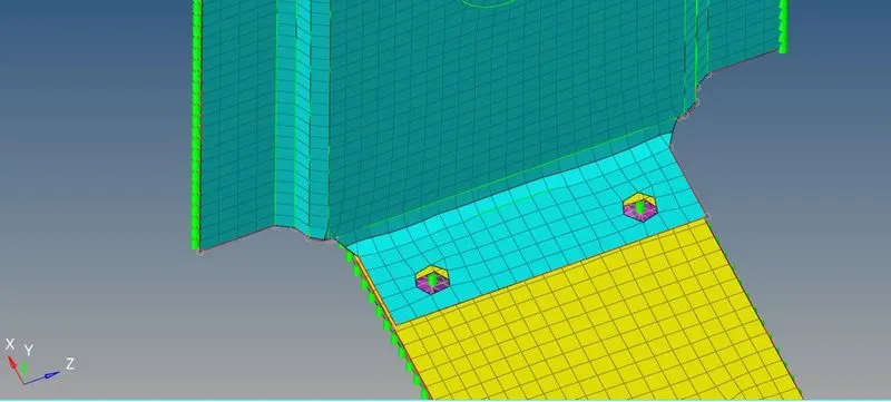
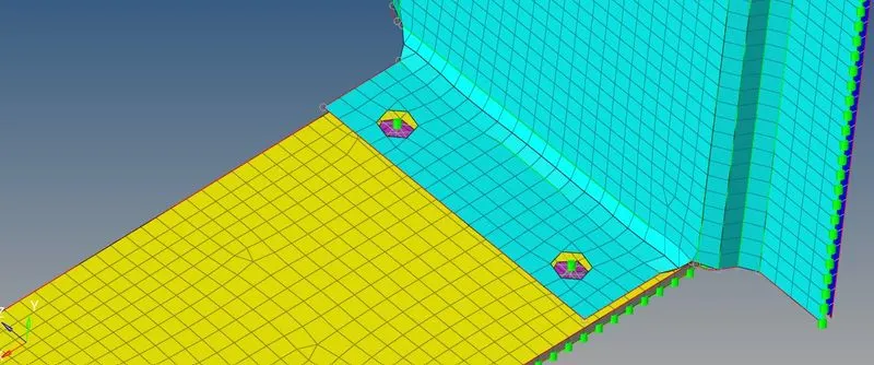
- 5th- Rear_truss_2 & Right_Rail_2:- Bolt Connector: In order to use bolt connection we will go to 2d> Connections>Bolt. And isolate the two components, the below image shows the procedure.

Since we have to create a hole for bolt we will select nodes at center, we will select nodes at each side of the right rail. Then we will select both components. We will give search tolearance. As there is no hole we will have to change to create hole, if none. The below image shows the results.
- 6th- Rear_truss_2 & Left_Rail_2:- Bolt Connector: Here we will use similar method as above. The bwlow image shows the results.
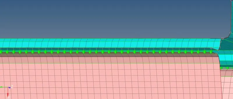
- 7th- Right_Rail_1 & Right_Rail_2:- Spot-weld with Rigid Elements: In order to create connection we will first isolate the two components. We will the go to 2d>Connectors>Spot we will keep the type as Rigid. The below image shows the setup.

Here we have to select the node list one on component. We will give spacing as 5 and select both the component. We will give dia of 5 and search distance. We will keep connection to be mesh dependent. The below image shows the results.
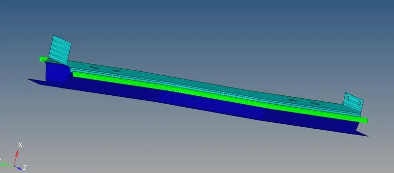
- 8th- Left_Rail_1 & Left_Rail_2:- Spot-weld (Spring Elements): To create connection we will first isolate the two components. We will the go to 2d>Connectors>Spot we will keep the type as Spring. The below image shows the setup.

We have to select the node list one on component. We will give spacing as 5 and select both the component. We will give dia of 5 and search distance. We will keep connection to be mesh dependent. The below image shows the results.
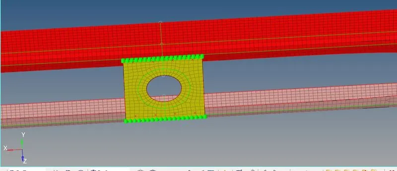
- Rest of components: For rest of components we used different connectors, below images shows the same.
Reinf Plate:
Rear Truss 1 &2:
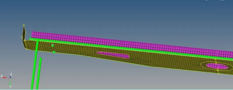
Con Rear Truss:
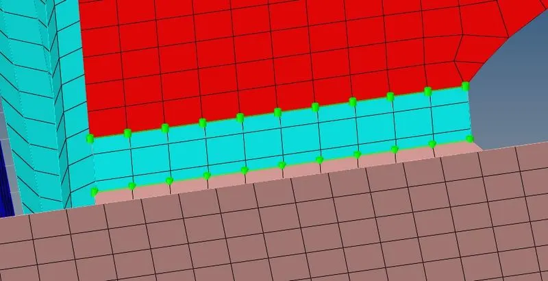
- Final Result: The below image shows the final result of the model after making all connections.
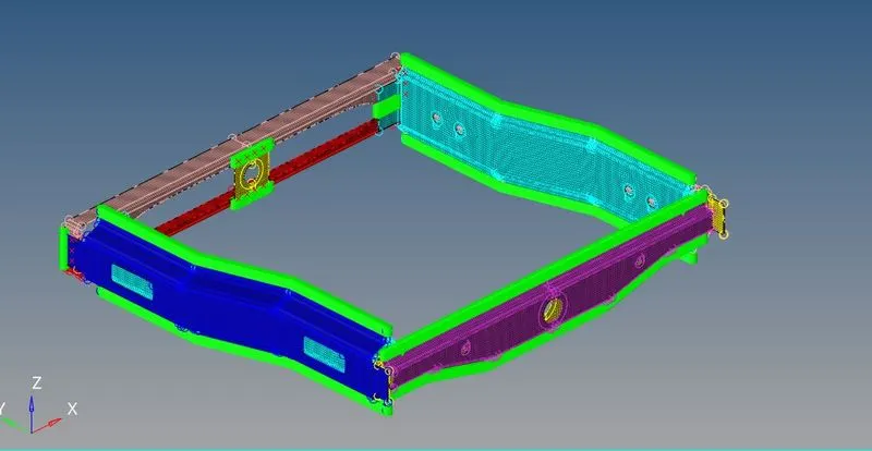
Conclusion: Hereby, we have eshed the model with given quality parameters with no failing elements. We have applied the connection as per requirement of the challange and used the mentioned connection type.