Week 4 -Wire Bending Challenge
Objective: We have to perform an analysis to simulate the bending of a wire in ANSYS. You will have to use Copper Alloy (Non-Linear), Aluminium Alloy (Non-Linear) and Magnesium Alloy (Non-Linear) for the wire alone. You need to find out the Equivalent stress and Equivalent strain on the wire alone. Compare the results and submit a well-formatted report on this.
Procedure:
- Importing and Checking Geometry
- Assigning Materials
- Setting Up contacts
- Meshing
- Applying Boundary conditions
- Solution
- Conclusion
We will start the Static Structural analysis in ANSYS Workbench:
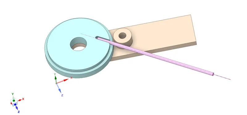
- Importing and Checking Geometry: We will import the given model and check for any error or geometrical errors in SpaceClaim, the model had no errors, the below image shows the same:
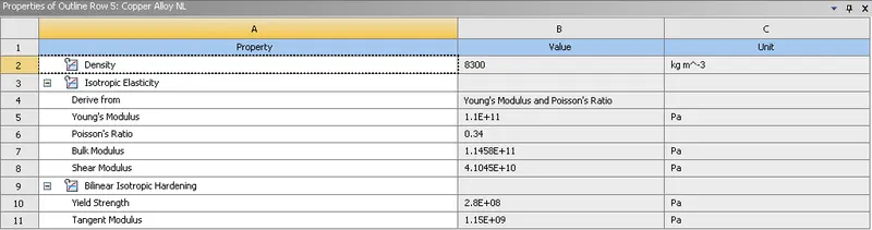
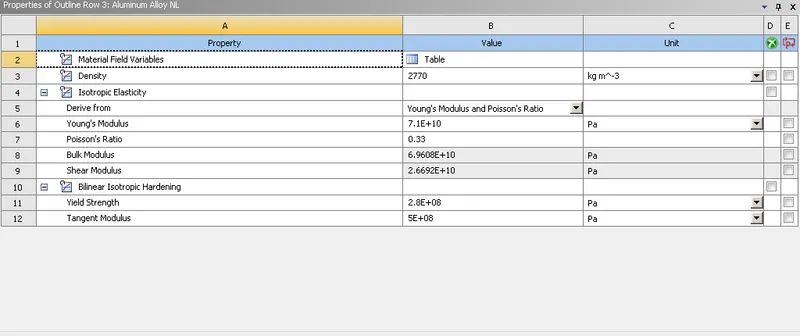
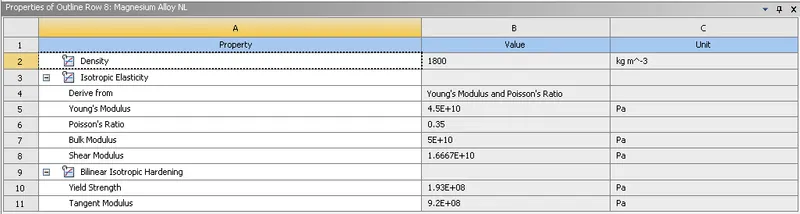
- Assigning Materials: For the given challenge we have to run the simulation for three different materials those Copper Alloy Non-Linear, Magnesium Alloy Non-Linear, Aluminium Alloy Non-Linear, below images shows the properties of all three materials:
Copper Alloy:
Aluminum Alloy:
Magnesium Alloy:
- Setting Up contacts: Once the model is updated in Mechanical and material is assigned to the wire we will proceed to assign the contacts. The first contact the wire will be the contact and the target will be Lever. Similarly, we will select all the faces of wheel on which wire will be bent, except for the bottom face. Below images shows the same:
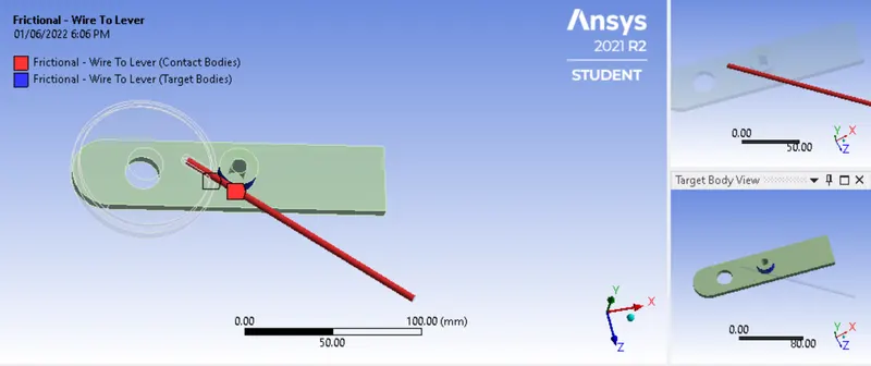
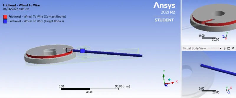
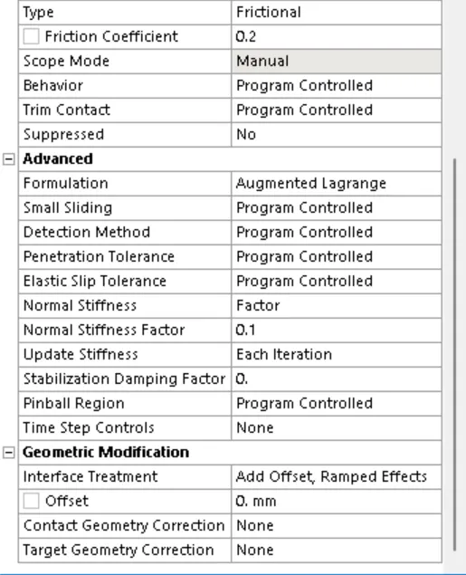
We will select both contacts and select the contact type as Frictional and the coefficient of friction as 0.2, normal stiffness factor will be 0.1, update iteration >for each iteration, interface treatment > add offset, ramped effects
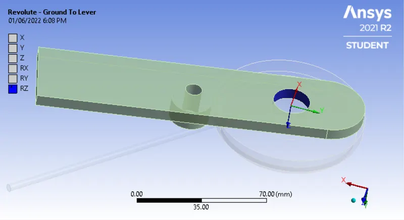
We will also assign revolute joint to the level, the rotation along Z-axis;
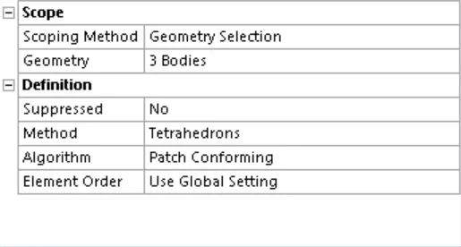
- Meshing: For meshing of the given model we will use Tetrahedrons as the method. We will assign the same to all three bodies.
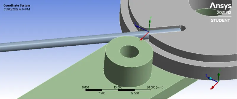
For Face meshing, we will assign a more refined mesh for the parts where more load is going to act we will select the face on which the wire is to be bent. And we will create a new coordinate as shown in the image below. Once done we create face meshing select the face, and use the type as the circle on influence and select the Coordinate system created.
Creating Coordinate System:
Create Face Meshing: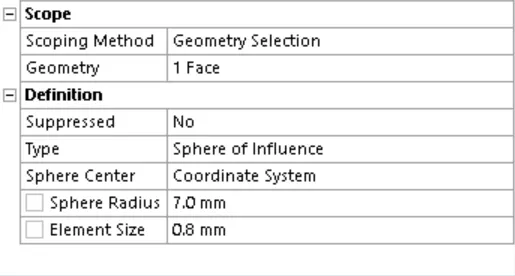
Meshed Face: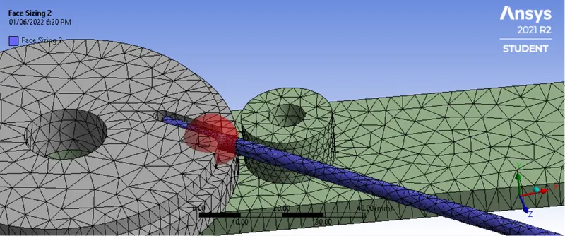
- Applying Boundary conditions: Once the mesh is created we can proceed to apply the boundary condition and Analysis Settings. We will run this simulation for 8 steps.
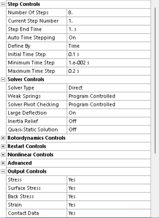
For the analysis, we will use different settings for the First step and for steps 2-8. The below images shows the settings applied for both cases;
For First Step:
For Steps 2-8: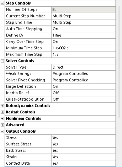
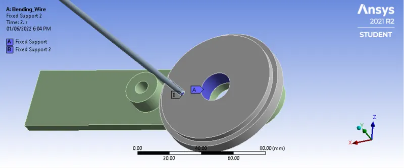
Applying Boundary Conditions: Once Analysis Settings are applied we will apply the boundary conditions, rotational joint load for the level, and fixed supports on the one end of the wire and on the wheel, the below image shows the same:
Rotational Joint Load: Below image shows the joint load on the lever, we will give rotation of 140 degrees to the lever, with 20 degrees for each step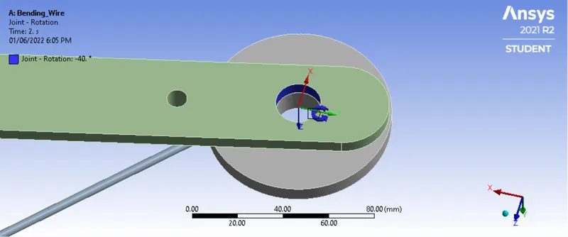
Fixed Supports:
- Solutions:
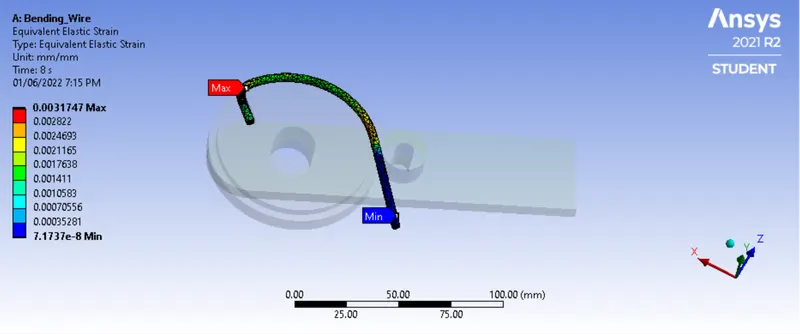
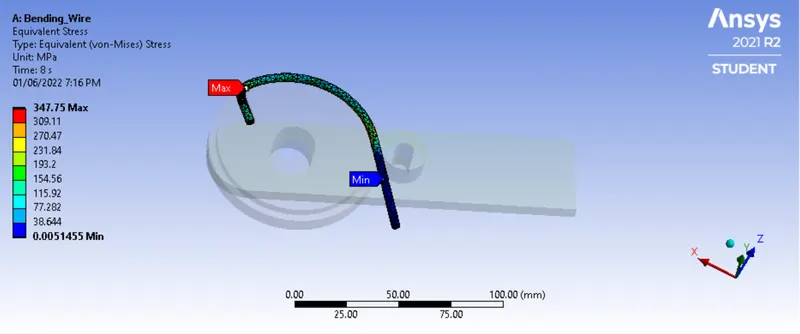
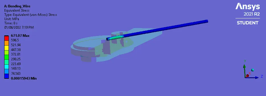
- Copper Alloy Non-Linear:
Equivalent Elastic Strain:
Equivalent Stress:
- Aluminium Alloy Non-Linear:
Equivalent Elastic Strain: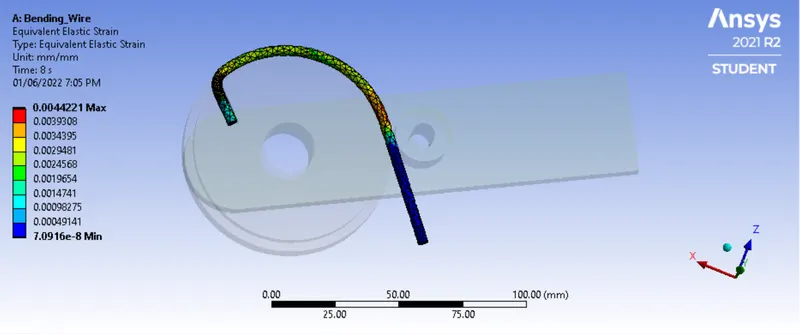
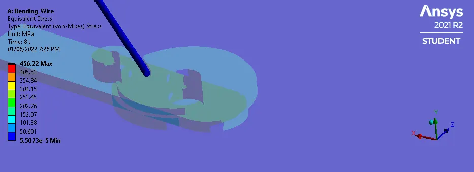
Equivalent Stress: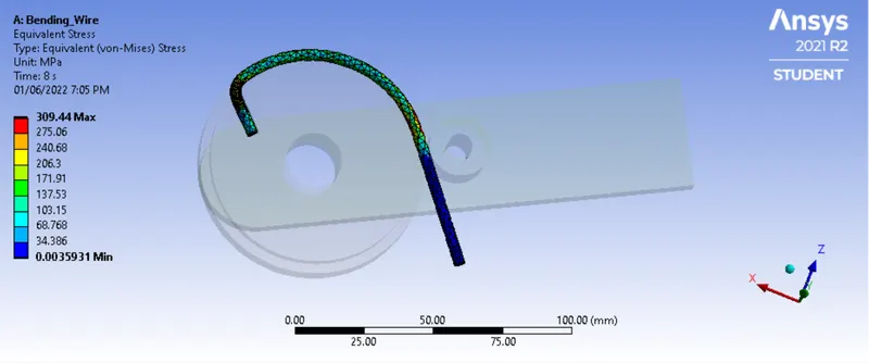
- Magnesium Alloy Non-Linear:
Equivalent Elastic Strain: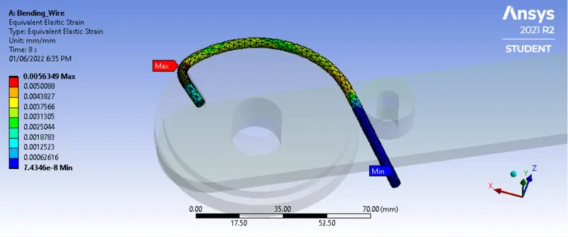
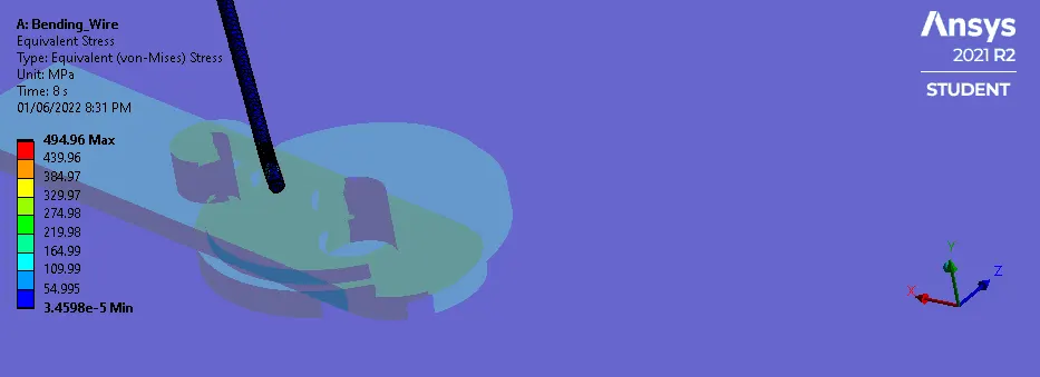
Equivalent Stress Non-Linear: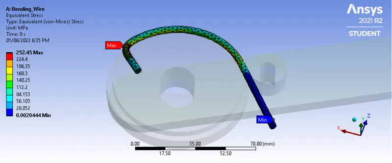
- Conclusion:
| Equivalent Elastic Strain | Equivalent Stress |
| Materials | Min | Max | Min | Max |
| Copper Alloy Non-Linear | 7.1737e-008 mm/mm |
3.1747e-003 mm/mm |
5.1455e-003 MPa | 347.75 MPa |
| Aluminium Alloy Non-Linear | 7.0916e-008 mm/mm |
4.4221e-003 mm/mm |
3.5931e-003 MPa | 309.44 MPa |
| Magnesium Alloy Non-Linear | 7.4346e-008 mm/mm |
5.6349e-003 mm/mm |
2.0444e-003 MPa | 252.45 MPa |
From the results above we can see that stresses developed are highest in Copper Alloy. However, it has the least Strain developed during the process of bending. The results shows the most plastic deformation is along the area where the wire is bent on the wheel. As the Magnesium Alloy has lower stiffness because it has lower elasticity modulus. Similarly, copper has higher stiffness because of high elasticity modulus. Thus, we can say that the material can be selected based on the application.