Morphing of CAD Model using ANSA
Week 8- Basics of Morphing
Objective: Practice all the Morphing techniques that were shown in the video for the given component. Write a report on Morphing and its use cases in various industries.
Introduction to Morphing: Mesh morphing consists of the adaption of a computational grid adopted for computer aided engineering (CAE). For instance, the solid or shell mesh of a structural part ready to be processed by an FEA solver, or the volume mesh complete with boundary conditions for a CFD solver, can take a new shape by just updating nodal positions. This means that the topology of the mesh (nodes count, cells count, connectivity) stays the same. Only the x,y,z coordinates of the nodes in the part of the model undergoing a shape modification are updated.
It can be used for different purposes for e.g. create shape parameters (i.e. change a length, an angle a thickness), move onto a new known shape (i.e. as manufactured, as designed by CAD).
Uses of Morphing in different indutries: Below are few uses of Morphing:
- Automobile Industry: In automobile industry in order to bring change in design of an existing model, for example face lifting of an existing running model. Morphing can also be used to meet design requirement during varoius checks and tests for e.g. Crash test, NVH etc. Morphing can be used to alter styling lines, scetions or proportions. It can also be used to bring small design changes to any component of the vehicle, as shown below.
- Aerospace Industry: In aerospace industry the use of Morphing of CAD models is used for optimizing existing model of an aircraft or to improve dynamics of any component.
- Energy Industry: Morphing in this case helps by bringing better results by giving few changes in design.
Procedure of Morphing in ANSA:
Importing model: Firstly, we imported the model from the storage in .STEP format to ANSA software.
The initial image of the goven model is shown below.
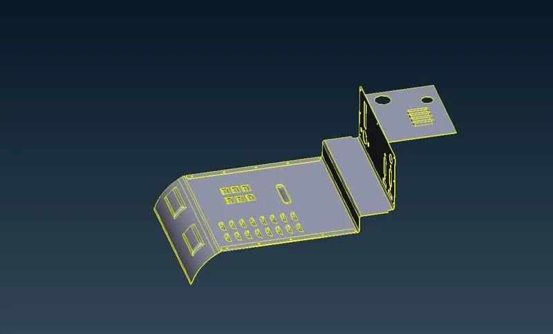
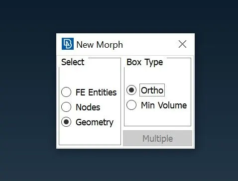
In order to Morph any particular feature of the CAD we need to create a box Morph Deck>Boxes> New> Ortho> Geometery
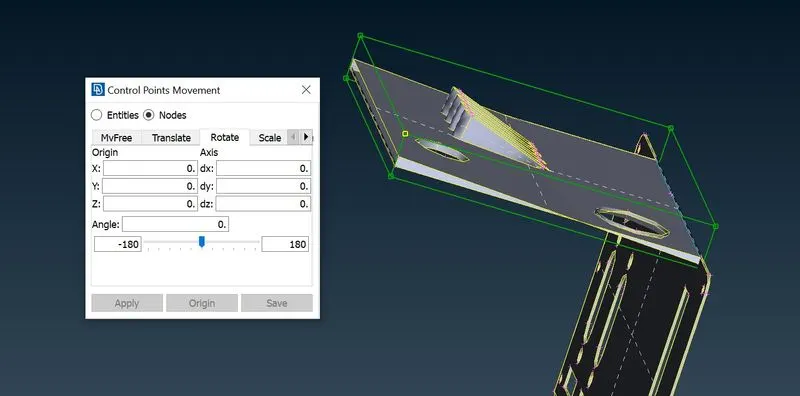
Once the box is created, in order to change shape we have to go to Boc Morphing>Move sleect the node for which direction we need to morph the model as shown below
Below is result of the feature after altering the design.
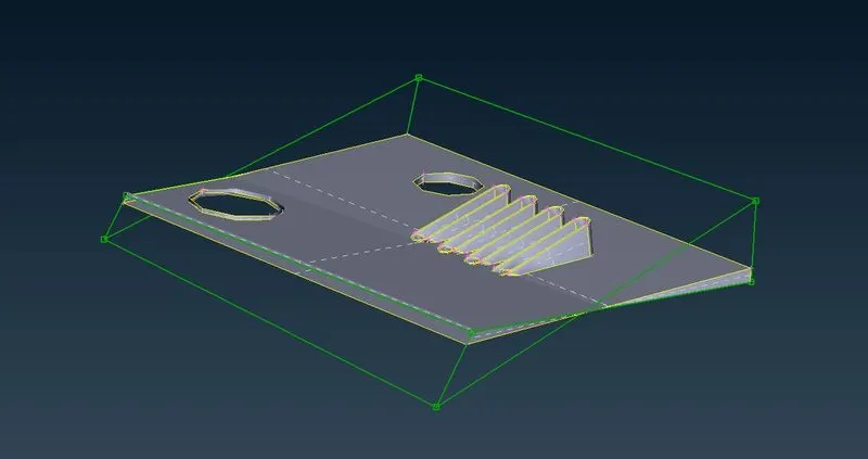
Split: The split option is used to devide Morphing boxes in desired number of parts. By splitting the box into smaller sections we can work and make changes to more smaller sections. In order to split, we have to select Boxes>split Once such example is shown below:
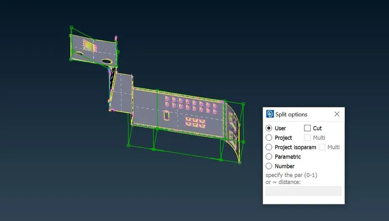
Below image shows marphing of one section of the feature after spliting the morphing box into smaller scetions.
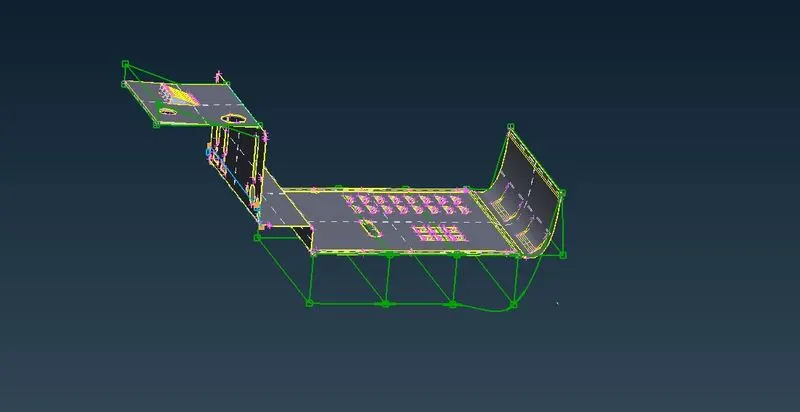
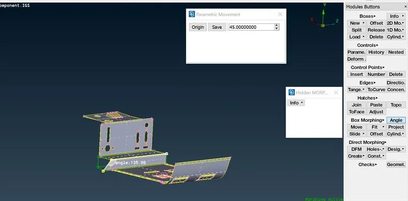
Angle: This tool can be used to change the angle betweeen any two neighbouring entities. We have to select Box Morphing> Angle. Below image shows the use of this tool:
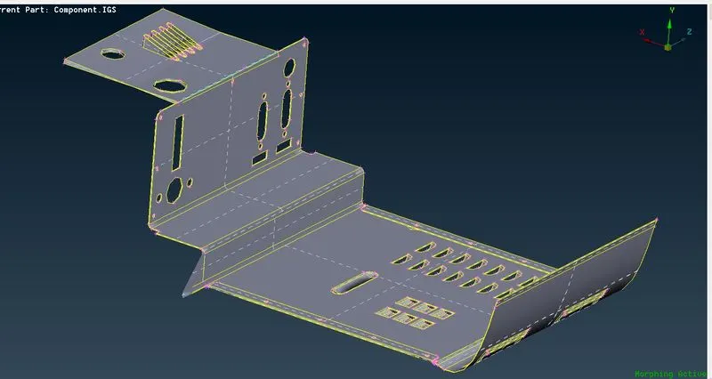
Boxes>Delete: Once all the required operations of marphing are done we can delete the boxes. The below image shows the model after making all changes.
Learning Outcome: By finshing this challange we learned to make changes to CAD design without any numerical input using Morphing. Also we got to learn its purpose and why it is useful.
Conclusion: Hereby, the given CAD model has been morphed using different tools. Also, its uses in different industries has been listed in this report.