Photo Realistic Rendering
PHOTOREALISTIC RENDERING
I. Objective:-
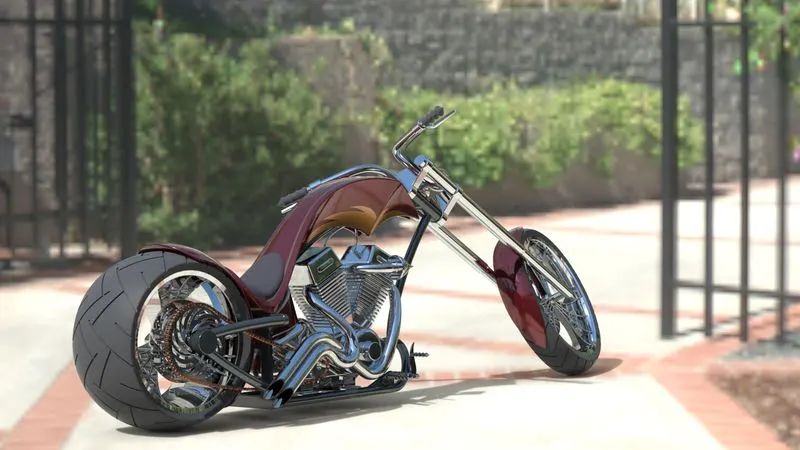
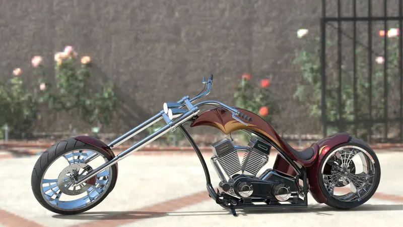
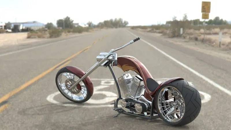
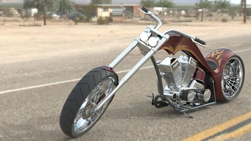
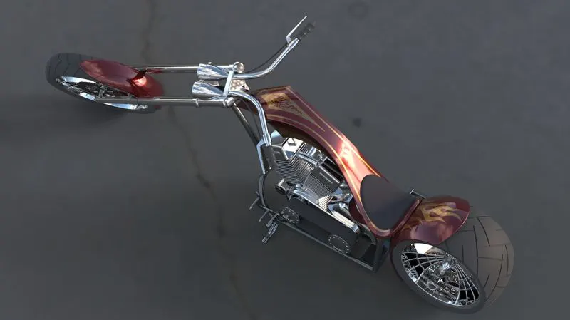
In this Project, the American Chopper model is to be created in Solidworks and rendered the chopper in Solidworks Visualize software.
II. Introduction:-
Software:-
In this Project, the Solidworks software is used to create the chopper model. Solidworks is a solid modelling computer-aided design (CAD) and computer-aided engineering (CAE) computer program published by Dassault Systemes.
American Chopper:-
A chopper is a type of custom motorcycle that emerged in California in the late 1950s. A chopper employs radically modified steering angles and lengthened forks for a stretched-out appearance. They can be built from the original motorcycle which is modified or built from scratch.
Choppers are a type cruiser, so-called because they are a "chopped", or cut-down, version of a production cruiser. Choppers are usually custom projects that result in a bike modified to suits the owner's ideas and, as such, are a source of pride and accomplishment.
Two famous examples of the chopper are customised Harley-Davidson and Billy Bike.
III. Design Methodology:-
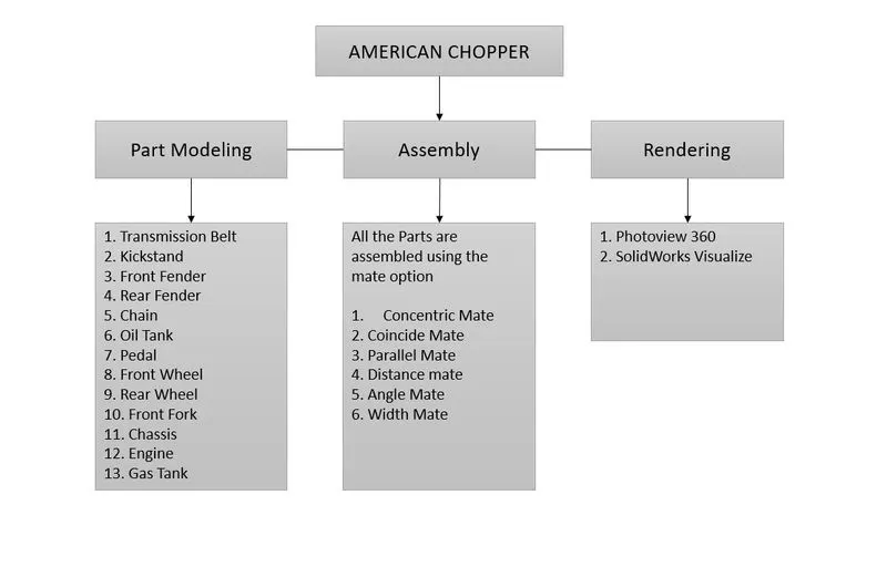
IV. Description:-
Features used in the part model of American Chopper
Sketch Tools:-
- Line
- Circle
- Arc
- Spline
- Rectangle
- Slot
- Sketch Fillet
- Sketch Chamfer
- Trim Entities
- Extend Entities
- Offset Entities
- Mirror Entities
- Convert Entities
- Smart Dimensions
- Geometric Constraints (Horizontal, Vertical, Collinear, Parallel, Tangent, Concentric, Equal, Coincident, Pierce)
1. Boss-Extrude:-
Extruded Boss/Base tool is used to create a solid volume by adding height to the selected sketch.
2. Revolve:-
Revolved Boss/Base tool is used to create a solid volume by revolving a sketch about a selected axis.
3. Sweep:-
The Swept Boss/Base tool is used to create a solid volume by moving a sketch along the selected path.
4. Loft:-
The Loft Base/Base tool is used to create a solid volume joining two or more sketches created on different planes.
5. Extruded Cut:-
The Extrude cut tool is used to remove material by extruding the sketch.
6. Revolve Cut:-
The Revolve Cut tool is used to remove material by revolving the sketch.
7. Swept Cut
The Swept Cut tool is used to remove material by sweeping a section along the specified path.
8. Fillet:-
The Fillet tool is used to apply radius at the edges. This tool works in the same way as the sketch fillet do.
9. Chamfer:-
The Chamfer tool is used to bevel the sharp edge of the model.
10. Linear Pattern:-
The Linear Pattern tool is used to create a linear pattern of solid features in the Modeling environment.
11. Circular Pattern:-
The Circular Pattern tool is used to create multiple instances of selected features around an axis.
12. Curve Driven Pattern:-
The Curve Driven Pattern tool is used to create multiple instances of solid features along the selected path.
13. Mirror:-
The Mirror tool is used to create a mirror copy of the features in the Modeling environment.
14. Shell:-
The Shell tool is used to make a solid part hollow and remove one or more faces.
15. Extruded Surface:-
The Extrude surface tool is used to extrude a close or open sketch to the specified height to form a surface.
16. Swept Surface:-
The swept surface tool is used to sweep a section along the selected path to form a surface.
17. Lofted Surface:-
The Lofted surface tool is used to join two open/close sections to form the surface.
18. Boundary Surface:-
The Boundary surface tool is used to join two open/close sections to form the surface.
19. Knit Surface:-
The Knit surface tool is used to combine the two or more surfaces at their common edges. If the surface forms a close boundary then this tool turns the surface into a solid.
The Part models of American chopper is,
- Transmission Belt
- Kickstand
- Front Fender
- Rear Fender
- Chain
- Oil Tank
- Pedal
- Front Wheel
- Rear Wheel
- Front Fork
- Chassis
- Engine
- Gas Tank
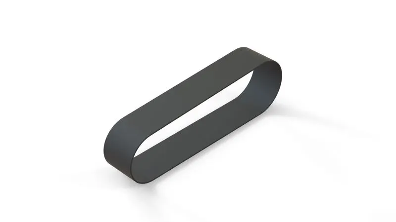
1. Transmission Belt
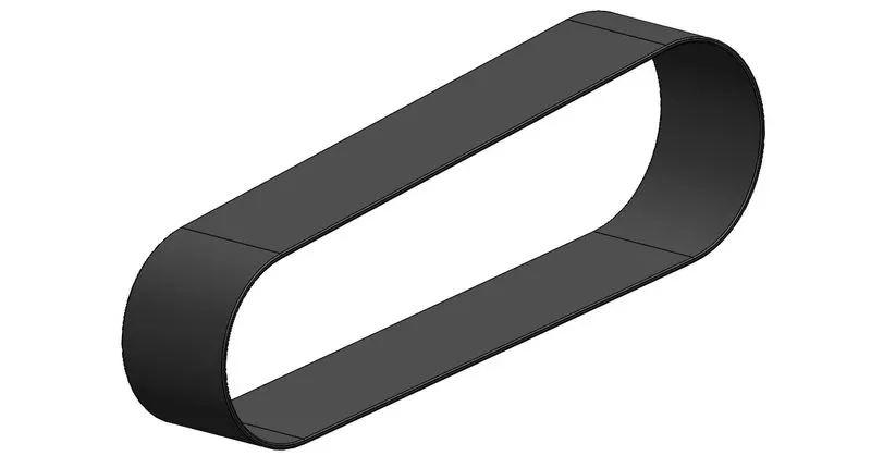
Features used:-
- Boss-Extrude
- Fillet
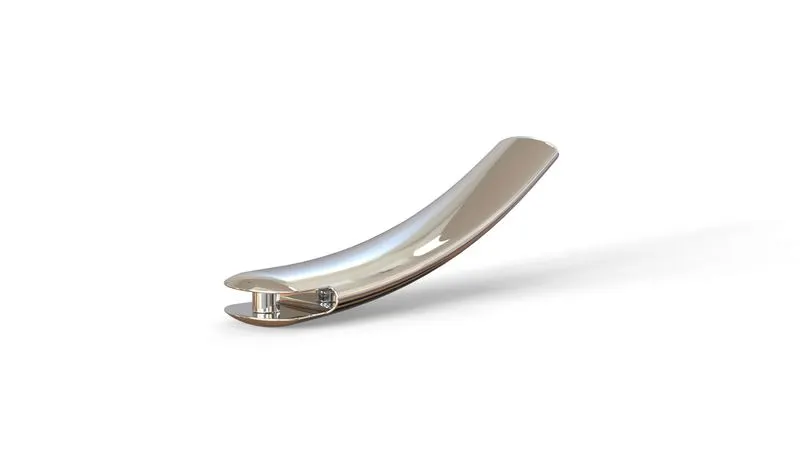
2. Kickstand
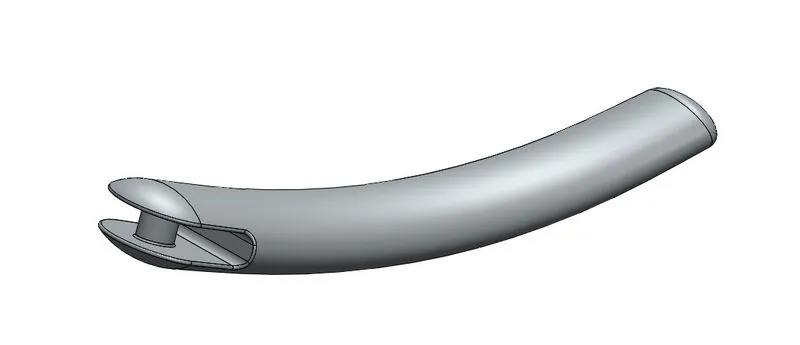
Features used:-
- Loft
- Dome
- Cut-Extrude
- Boss-Extrude
- Split
- Fillet
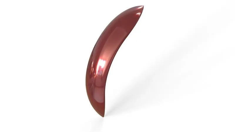
3. Front Fender
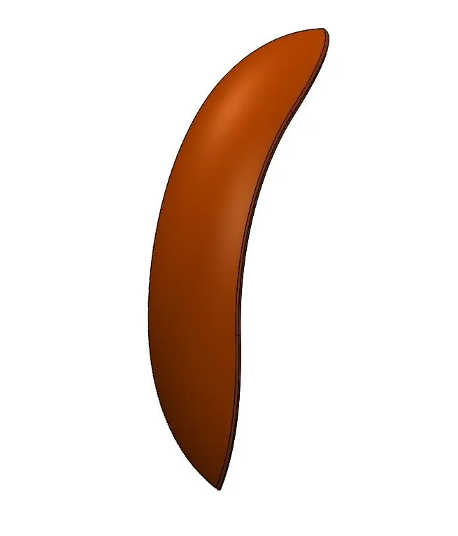
Features used:-
- Revolve
- Split
- Fillet
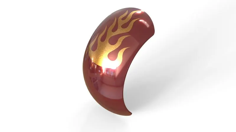
4. Rear Fender
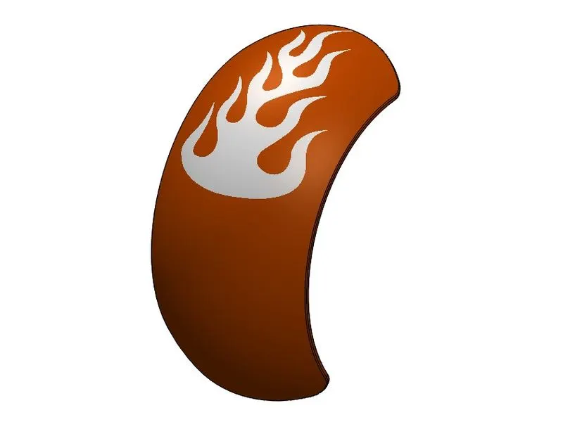
Features used:-
- Revolve
- Split
- Fillet
- Shell
5. Chain
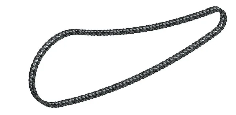
Features used:-
- Boss-Extrude
- Fillet
- CurvePattern
- Mirror
6. Oil Tank
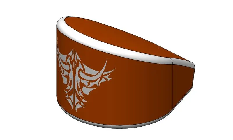
Features used:-
- Boss-Extrude
- Fillet
- Combine
- Shell
7. Pedal
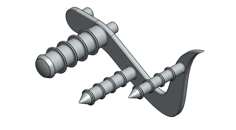
Features used:-
- Boss-Extrude
- Fillet
- Revolve
- Dome
- Chamfer
- Linear Pattern
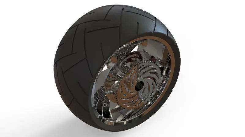
8. Front Wheel
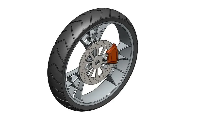
Features used:-
- Revolve
- Boss-Extrude
- Cut-Extrude
- Cut-Revolve
- Circular pattern
- Combine
- Fillet
- Chamfer
9. Rear Wheel
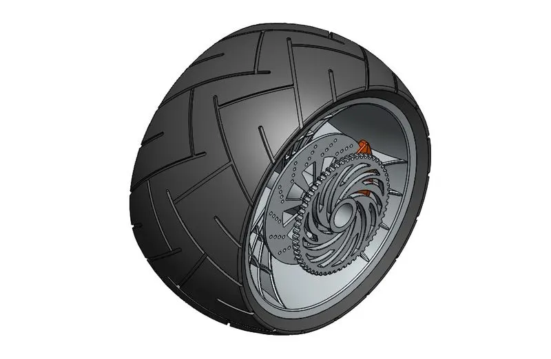
Features used:-
- Revolve
- Boss-Extrude
- Cut Extrude
- Circular Pattern
- Combine
- Cut-Revolve
- Fillet
- Chamfer
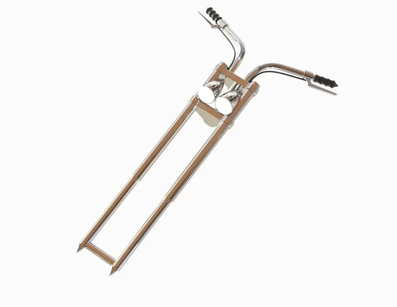
10. Front Fork
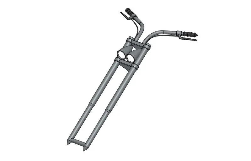
Features used:-
- Revolve
- Boss-Extrude
- Fillet
- Linear Pattern
- Boss-Extrude
- Cut-Extrude
- Dome
- Cut-Revolve
- Curve
- Sweep
- Combine
- Mirror
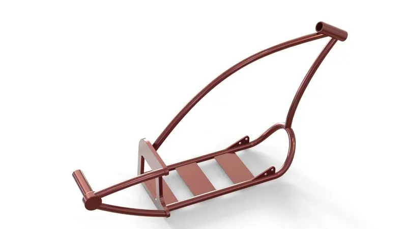
11. Chassis
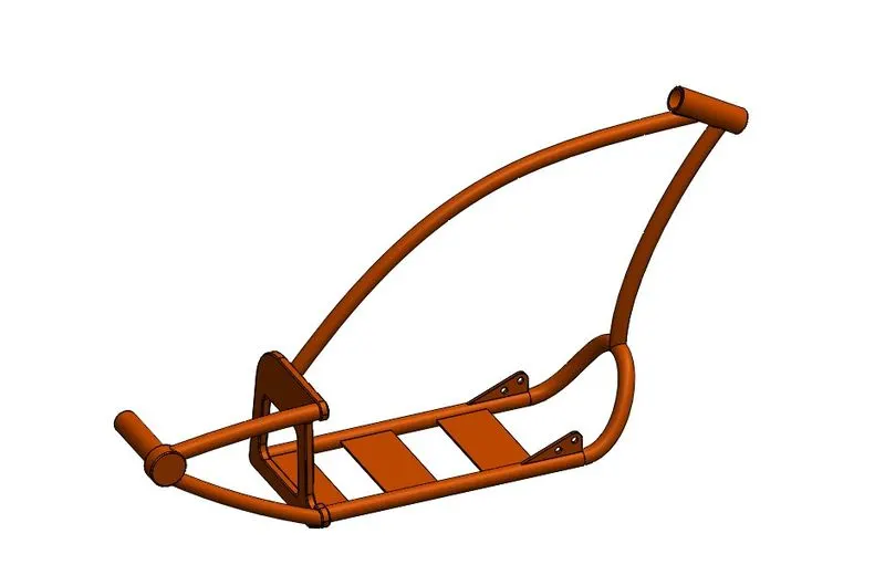
Features used:-
- Curve
- Sweep
- Mirror
- Boss-Extrude
- Cut-Extrude
- Chamfer
- Fillet
- Split
- Combine
- Revolve
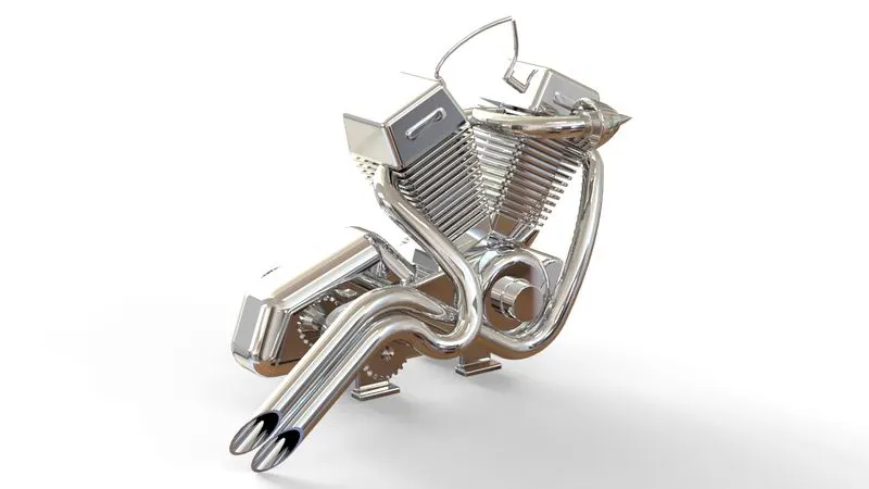
12. Engine
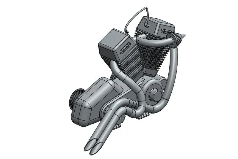
Features used:-
- Boss-Extrude
- Fillet
- Revolve
- Circular Pattern
- Boss-Extrude
- Dome
- Cut-Extrude
- Chamfer
- Linear Pattern
- Mirror
- Sweep
- Combine
- Curve
- Composite Curve
- Split
13. Gas Tank
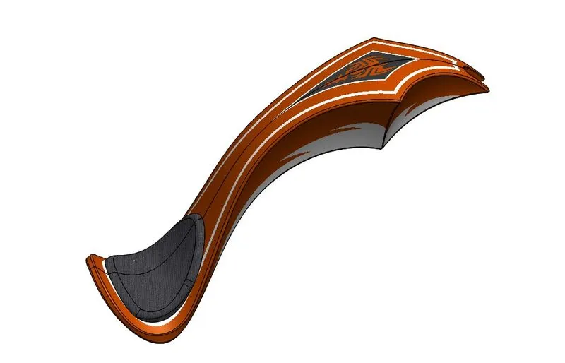
Features used:-
- Surface Sweep
- Surface Trim
- Curve
- Surface-Loft
- Boundary-Surface
- Mirror
- Surface-Knit
- Split Line
- Surface Extrude
- Fillet
- Shell
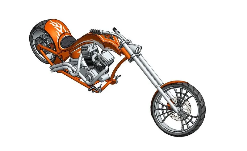
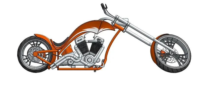
V. Assembly Model:-
Isometric View
Front View
Top View
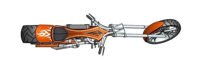
Left Side View
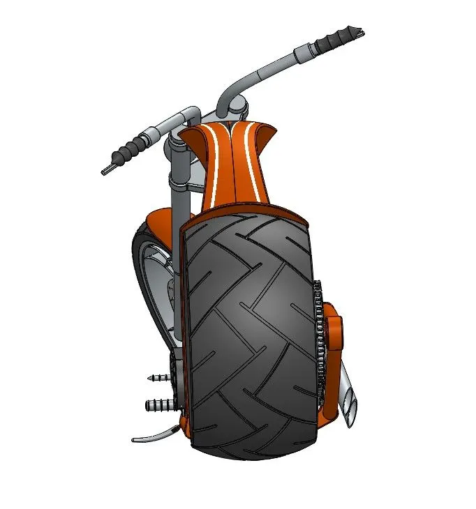
Right Side View
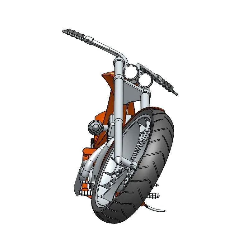
Camera View
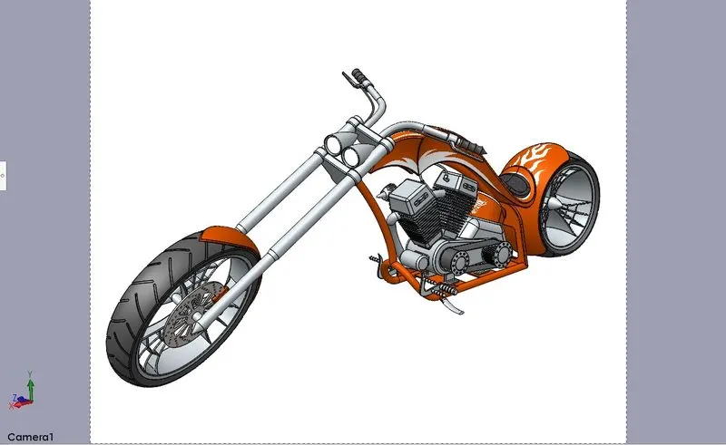
VI. Rendering Image:-
i) Part Model:-
1. Transmission Belt
2. Kickstand
3. Front Fender
4. Rear Fender
5. Chain
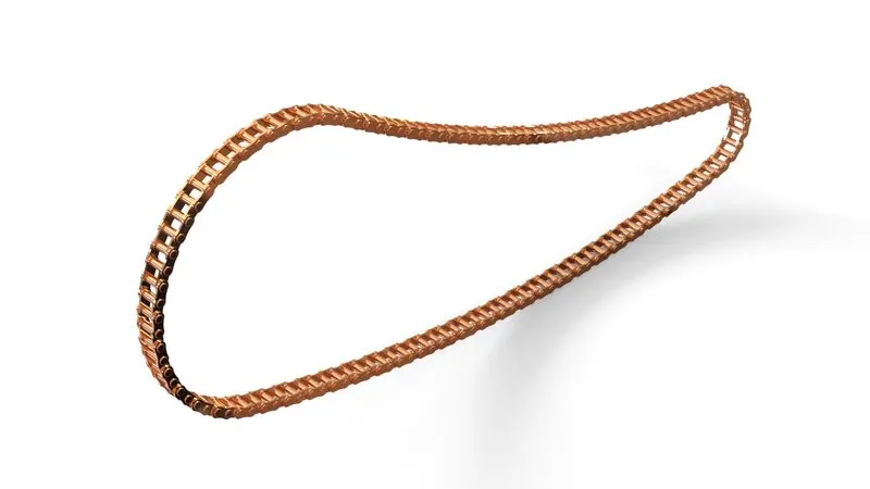
6. Oil Tank
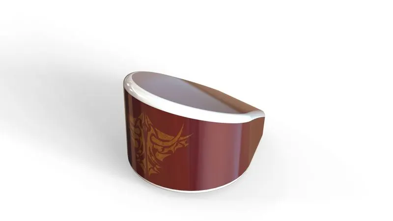
7. Pedal
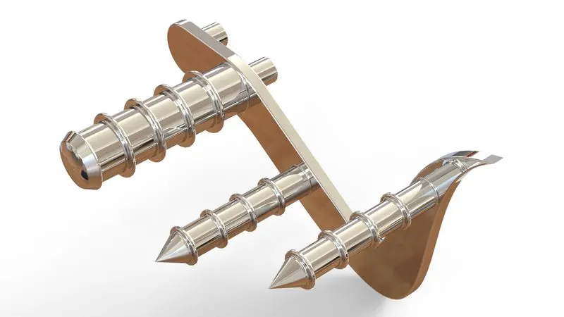
8. Front Wheel
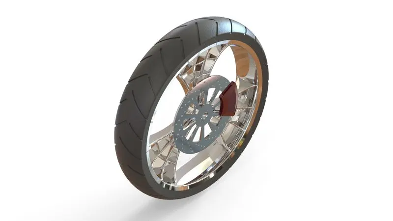
9. Rear Wheel
10. Front Fork
11. Chassis
12. Engine
13. Gas Tank
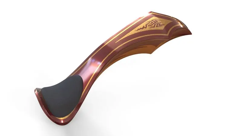
ii) Assembly Model
Conclusion:-
From this project, I conclude that the part model and assembling model is rendered using SolidWorks Visualization.
Project Model Links:-
1. Render Model and Assembly file
2. Image Link