Week 4.1: Project Steady state simulation of flow over a throttle body
STEADY-STATE SIMULATION OF FLOW OVER A THROTTLE BODY
Aim:-
To simulate the flow over a steady-state simulation of flow over a throttle body.
Objective:-
- Perform a steady-state simulation of flow over a throttle body
- Post-process the result and show pressure and velocity contours.
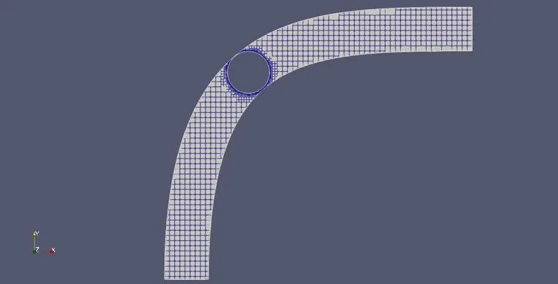
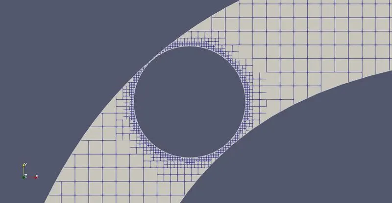
- Show the mesh with surface edges.
- Show the plots for pressure, velocity, mass flow rate and total cell count.
Introduction:-
Throttle Body:-
In fuel-injected engines, the throttle body is the part of the air intake system that controls the amount of air flowing into the engine, in response to driver accelerator pedal input in the main. The throttle body is usually located between the air filter box and the intake manifold, and it is usually attached to the mass airflow sensor.
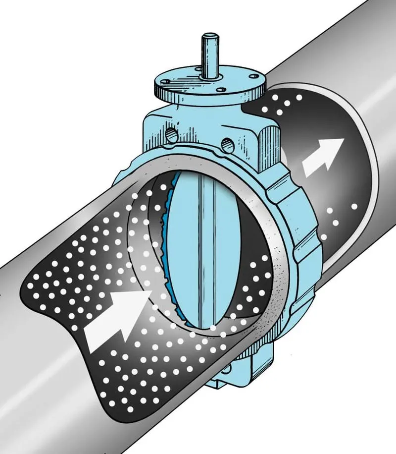
The largest piece inside the throttle body is the throttle plate, which is a butterfly valve that regulates the airflow.
Simulation Process
A. Geometry Setup:-
- Import the elbow.stl file in converge CFD.
- And scale the geometry from millimetre to meter.
- Creating the boundary face and delete the thickness of the elbow.
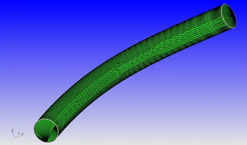
- After deleting the thickness the open edge is created. To The open edge is closed by patch command.
Geometry:-
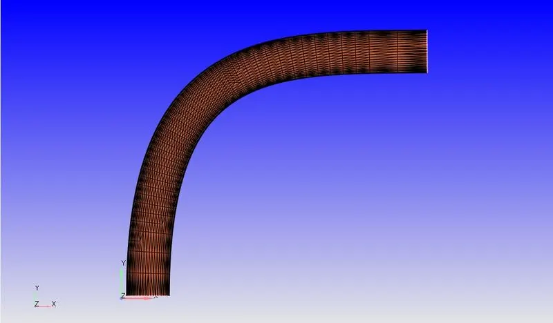
Scaling:-
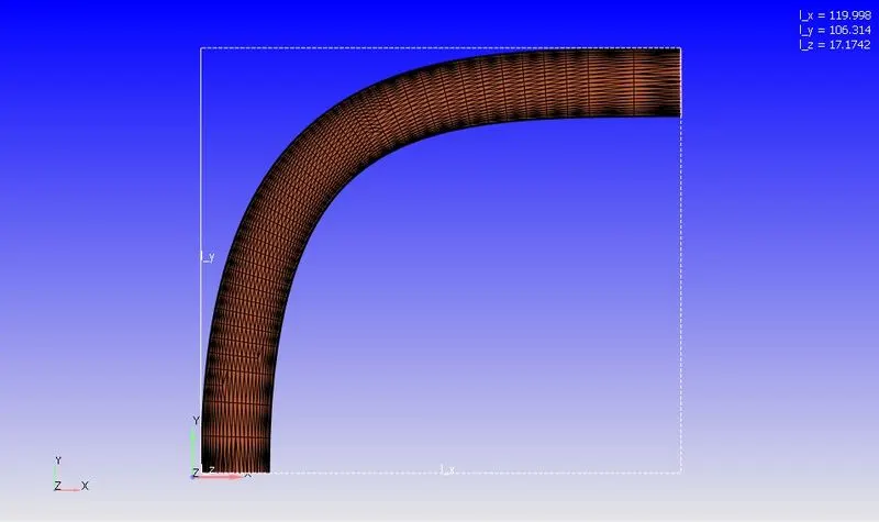
Fig(a). Before scaling
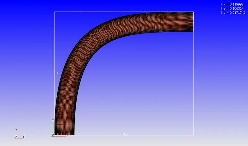
Fig(b). After scaling
Delete surface thickness:-
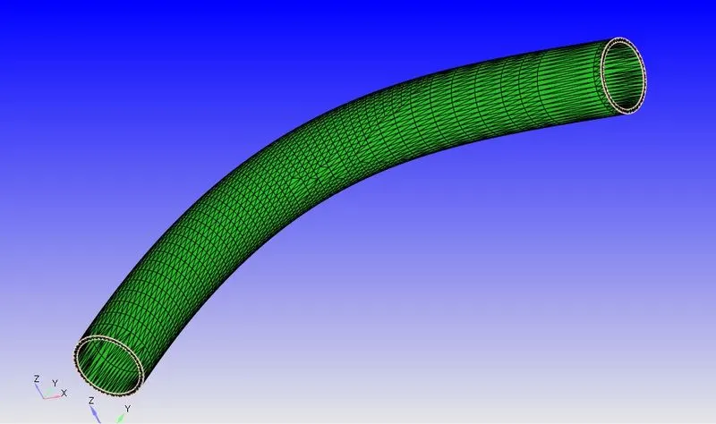
Fig(c). Boundary Fencing
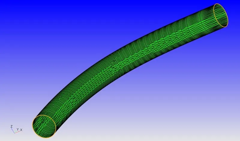
Fig(d). After deleting the surface
Patch:-
Boundary Flagging:-
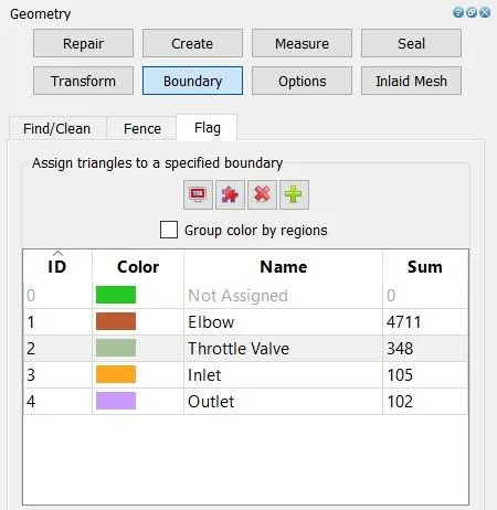
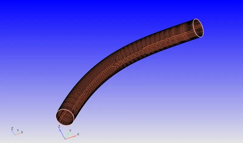
Fig(a). Elbow
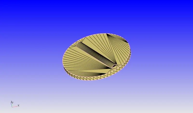
Fig(b). Throttle (or) Butterfly Valve
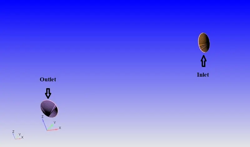
Fig(c). Inlet and Outlet
B. Case Setup:-
1. Application Type:-
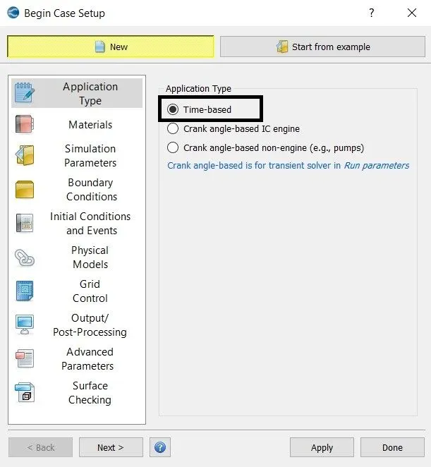
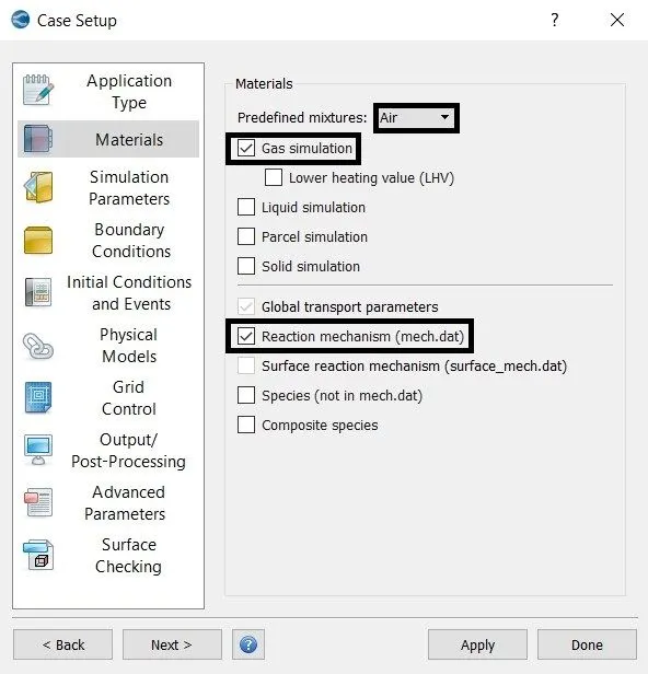
2. Material:-
3. Simulation Parameters:-
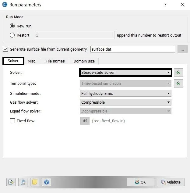
- A steady-state solver is used.
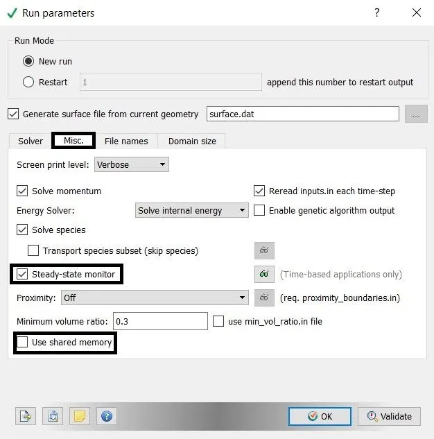
- The steady-state monitor is enabled.
- Use share memory is unchecked.
4. Steady-state monitor:-
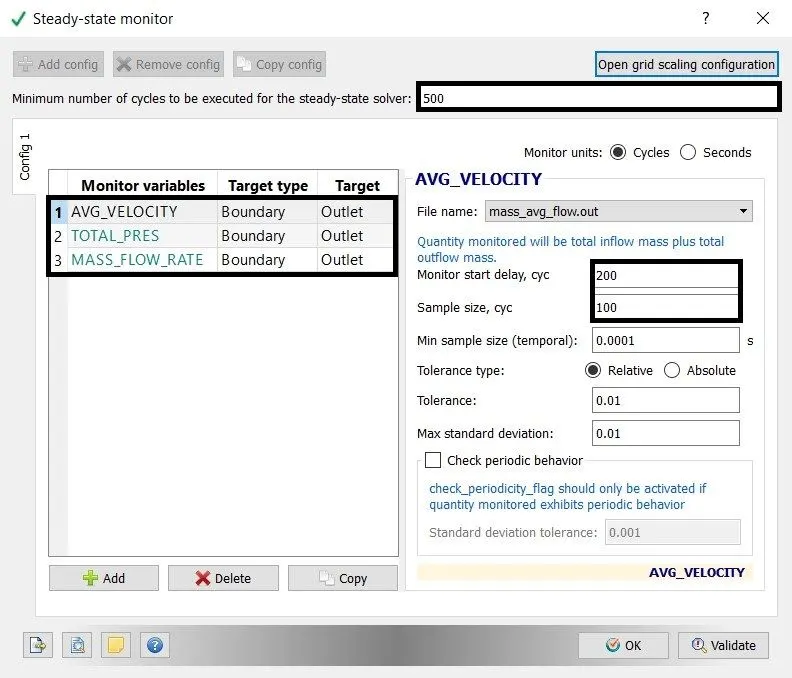
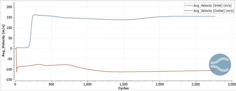
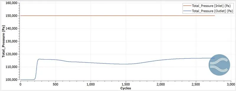
- Average Velocity, Total Pressure and Mass flow rate is monitored at outlet boundary conditions.
- A minimum number of cycles to be executed for the steady-state solver is 500.
- Monitor start delay = 200 cycles
- Sample size = 100 cycles.
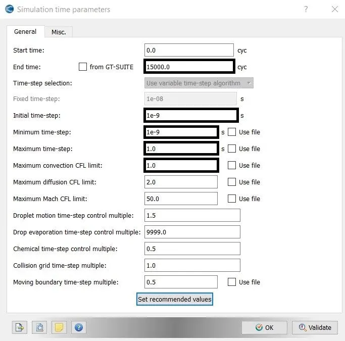
5. Simulation time parameters:-
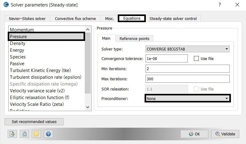
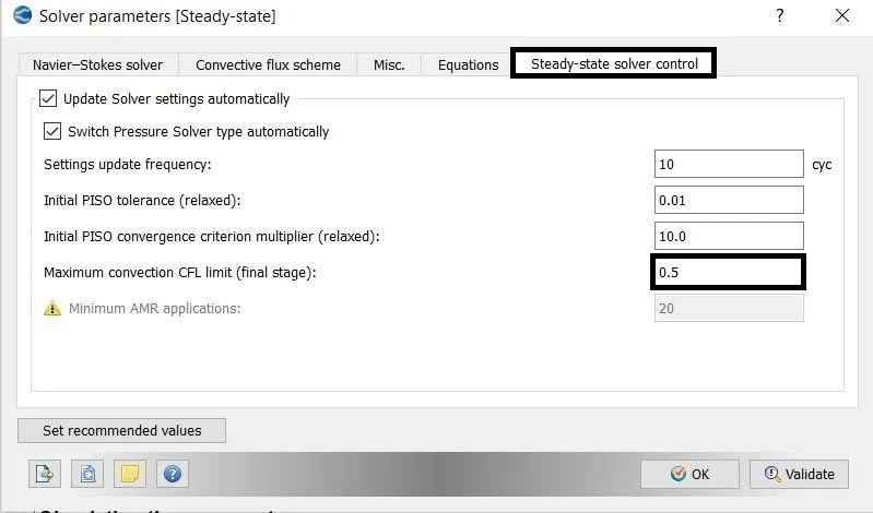
6. Solver Parameters:-

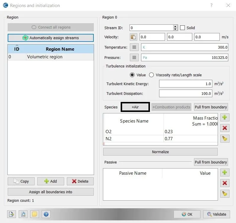
7. Region and Initialization:-
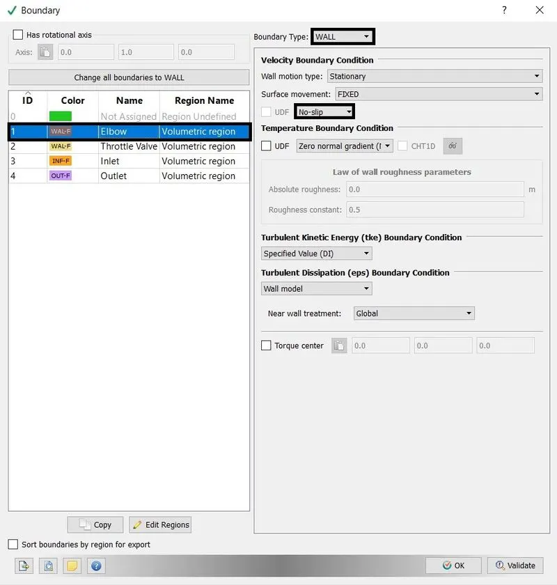
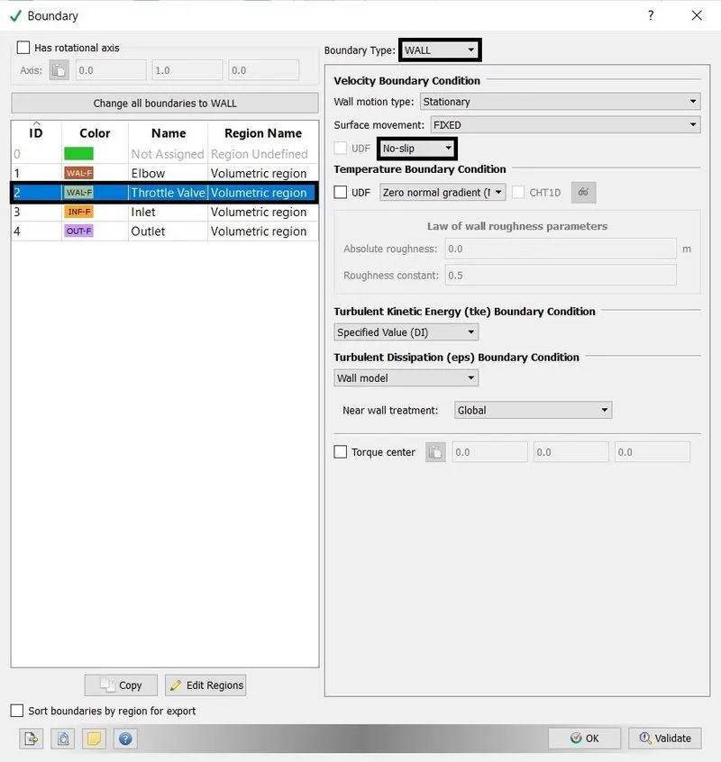
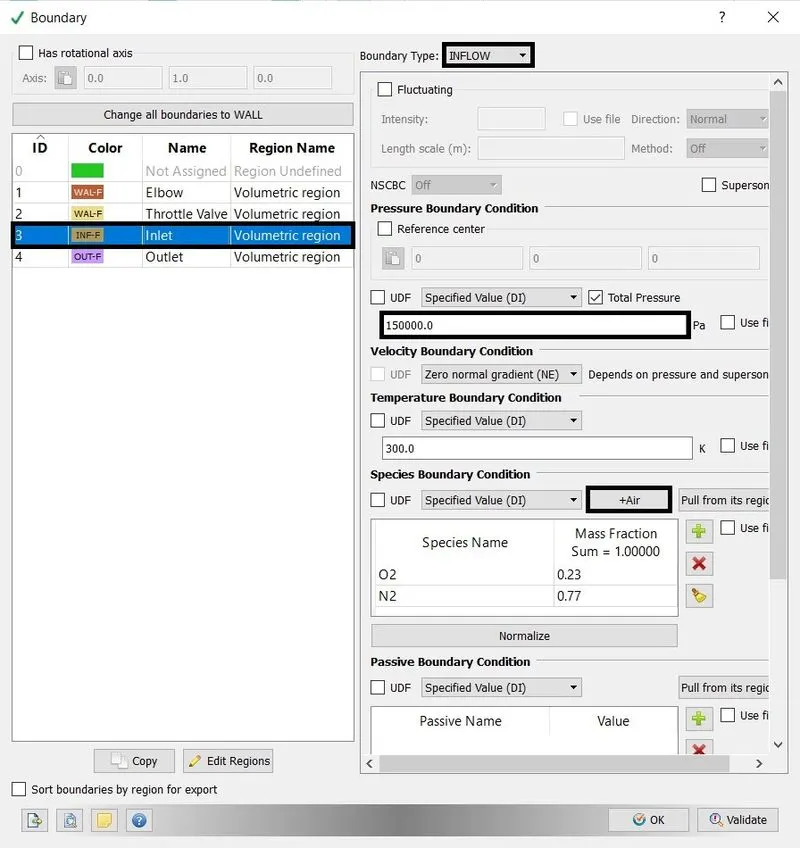
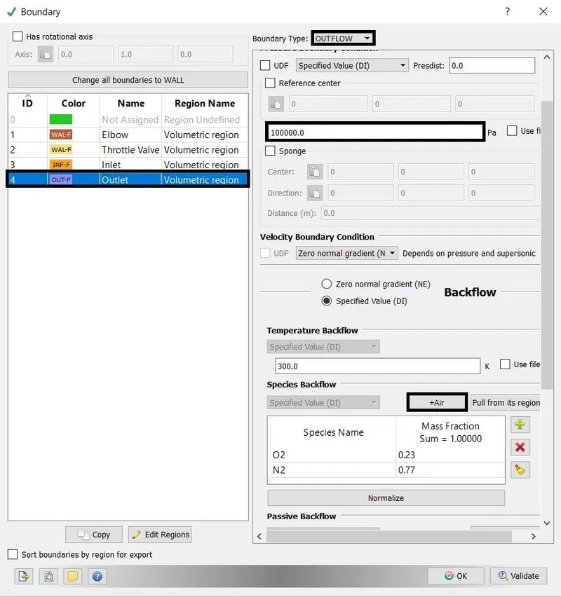
8. Boundary Conditions:-
- Elbow = wall with No-slip condition.
- Throttle Valve = wall with No-slip condition.
- Inlet = Inflow with 150000 Pa.
- Outlet = Outflow with pressure 100000 Pa.
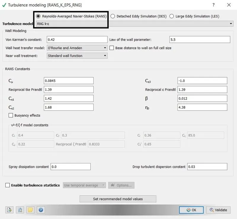
9. Physical model:-
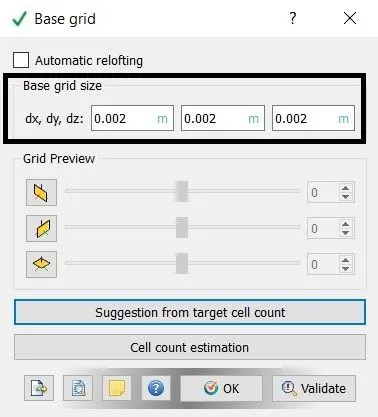
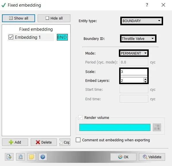
10. Grid Control:-
- Base grid
- Fixed Embedding.
11. Output/Post-processing:-
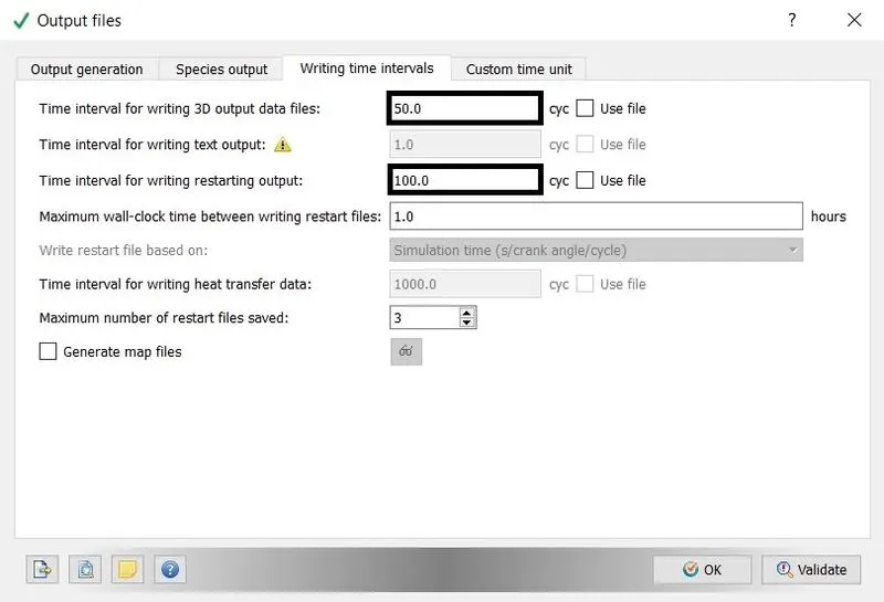
writing time intervals = 50 cycles
12. Export Data:-
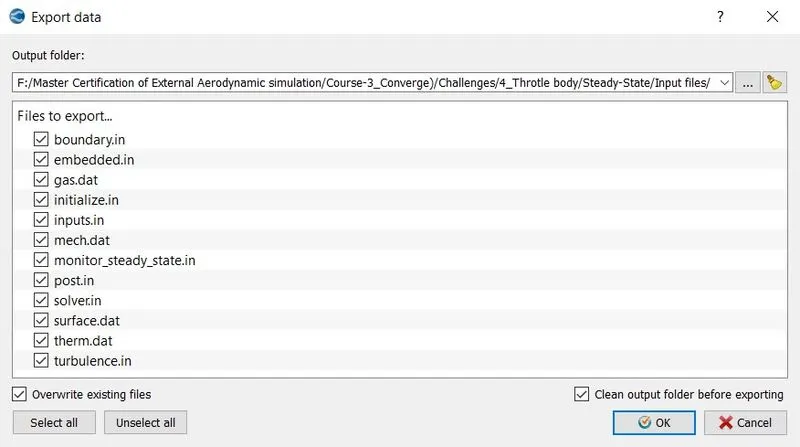
Export all input file in the directory to run the simulation in Cygwin.
C. Execute the Simulation:-
- The Executable "mpiexec.exe" and "converge.exe" are pasted in the input files.
- To run the simulation in Cygwin using the command.
mpiexec.exe -n 2 converge.exe restricted </dev/null> logfile &

- Converge at 2767 cycles
- Time Taken = 617.21 sec
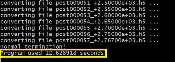
After the simulation is complete, the output files can be converted into Paraview VTK in-line binary Format to Post-process the result in Paraview.
mpiexec.exe -n 2 post_convert_30_msmpi.exe
D. Post-Processing the result in Paraview:-
1. Mesh:-
2. Velocity Contour:-
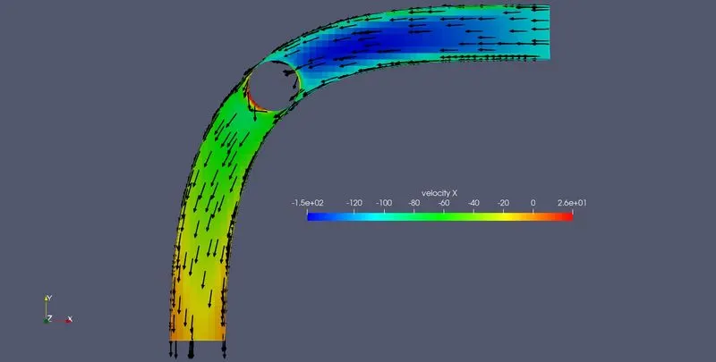
Fig(a). Velocity contour
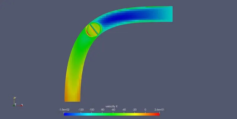
Fig(a). Velocity contour in the throttle valve
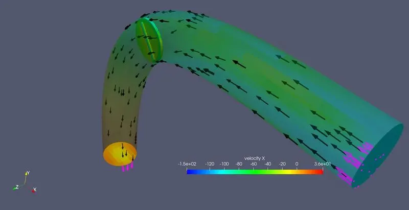
Fig(a). Velocity contour at inlet throttle
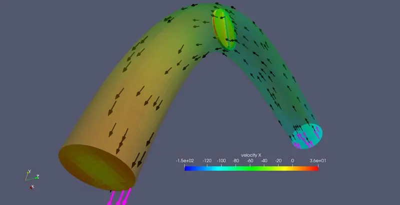
Fig(a). Velocity contour at outlet throttle
3. Pressure Contour:-
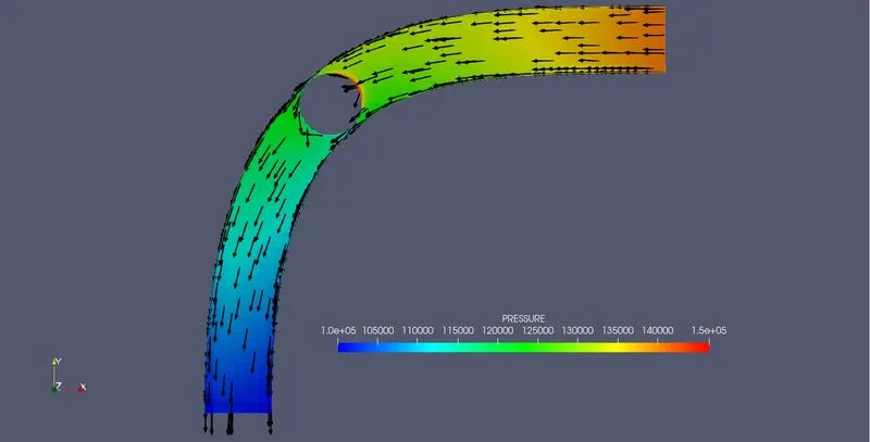
Fig(a). Pressure contour
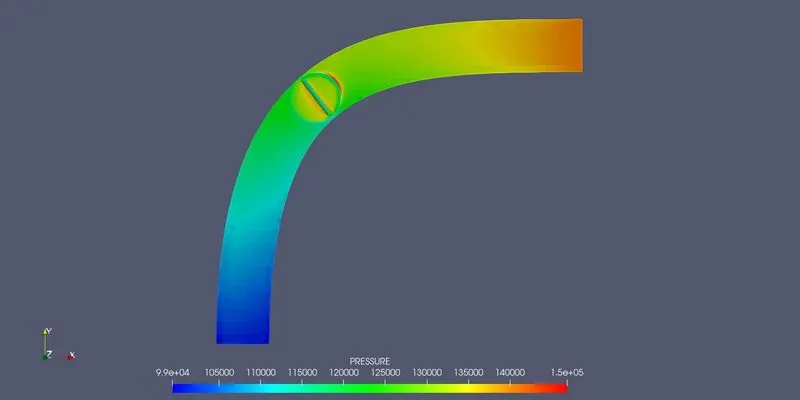
Fig(b). Pressure contour in the throttle valve
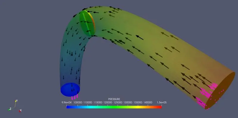
Fig(c). Pressure contour at inlet throttle
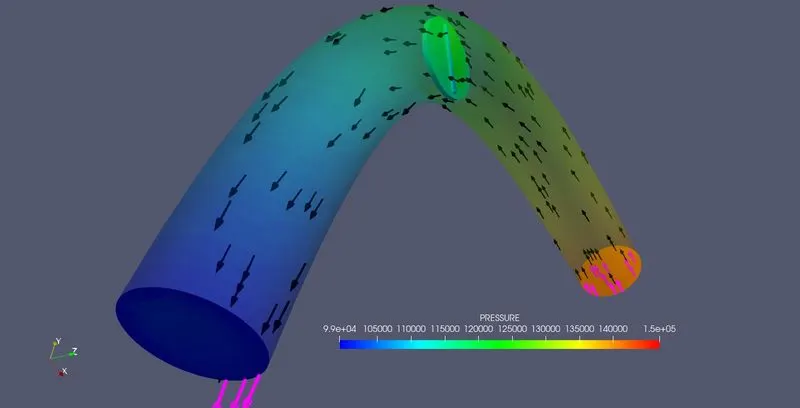
Fig(d). Pressure contour at outlet throttle
4. Average Velocity line plot:-
5. Total Pressure line plot:-
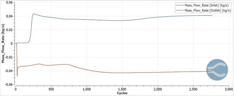
6. Mass Flow Rate line plot:-
7. Total Cell Count:-
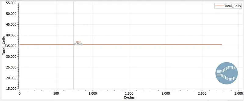
Total Cell Count = 35518
8. Animation:-
Velocity:-
Pressure:-
E. Conclusion:-
- In a steady-state simulation, the flow of air is observed in the throttle body with variables of velocity and pressure.
- For steady-state, the throttle valve is stationary when the airflow through the elbow.
- The mass flow rate at the inlet and outlet is 0.04 kg/s. Because the throttle valve is stationary and flow is steady-state so the airflow cannot be controlled.
- The total cell count is 35518 through the entire cycle there are no changes in cell count.
- The pressure is high in the inlet of the elbow and the inlet throttle valve region.
- The Velocity is high in the outlet of the elbow and the outlet throttle valve region.
- Bernoulli's formula explains the relation of pressure and velocity is inversely proportional. It means that when pressure increases, the velocity decreases, keeping the algebraic sum of potential energy, kinetic energy, and pressure constant.