Radar Mast & Final Assembly of Yacht
RADAR MAST AND FINAL ASSEMBLY OF YACHT
1. RADAR MAST
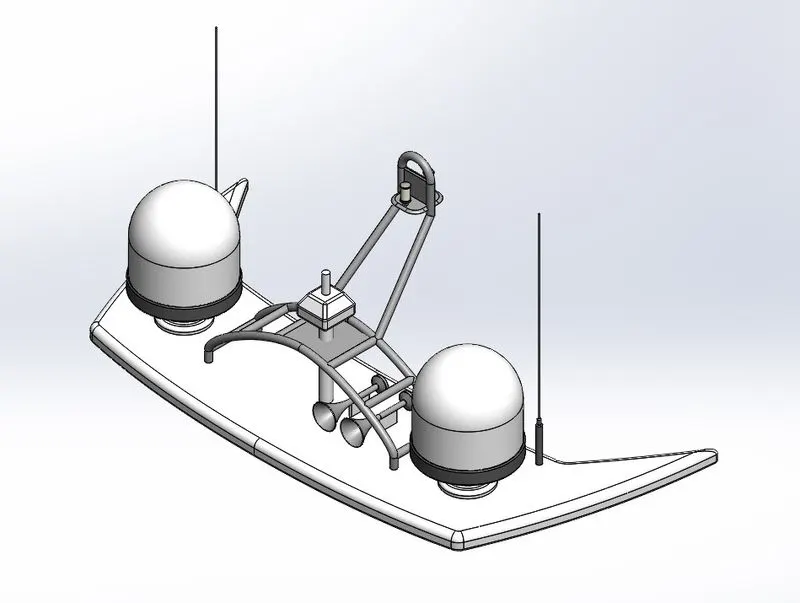
Isometric view:-
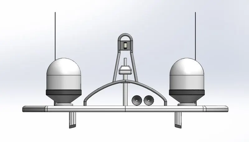
Front view:-
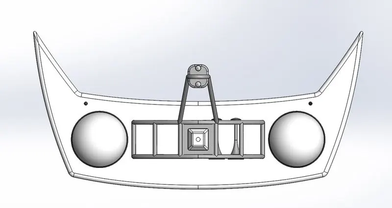
Top view:-
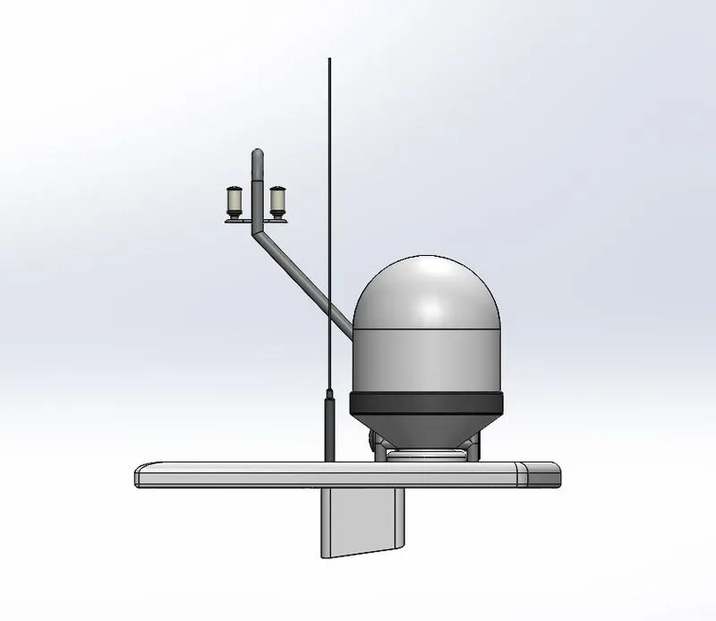
Side view:-
Feature tree:-
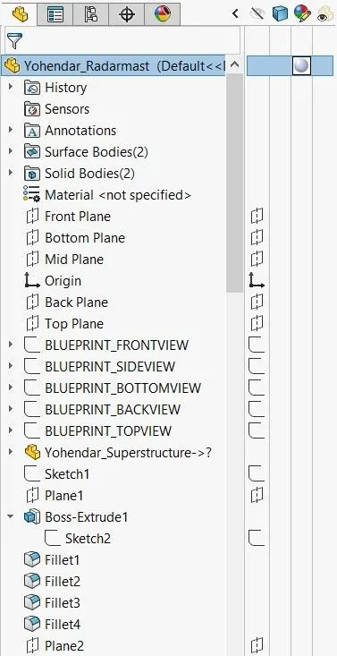
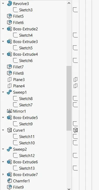
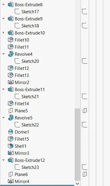
****************************************************************************************************
2. YACHT MODELLING
I. Objective:-
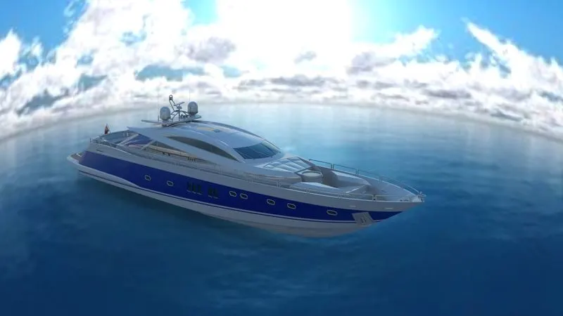
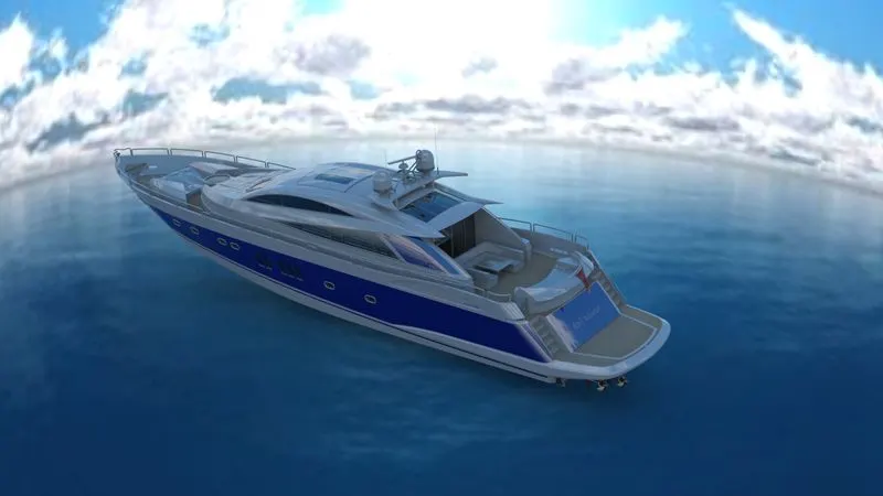
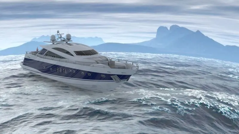
In this project, the yacht model is to be created Solidworks and rendered the yacht in Solidworks visualize software.
II. Introduction:-
Yacht:-
- A yacht is a sailing or power vessel used for pleasure, cruising, or racing. There is no standard definition, so the term applies to such vessels that have a cabin with amenities that accommodate overnight use. to be termed a yacht, as opposed to a boat, such a pleasure vessel is likely to be at least 33 feet (10m) in length and may have been judged to have good aesthetic qualities.
- The commercial yacht code classifies yachts 79 ft (24m) and over as large. Such yachts typically require a hired crew and have higher construction standards.
- Racing yachts are designed to emphasize performance over comfort. Charter yachts are run as a business for profit. As of 2020, there were more than 15000 yachts sufficient to require a professional crew.
III. Design methodology:-
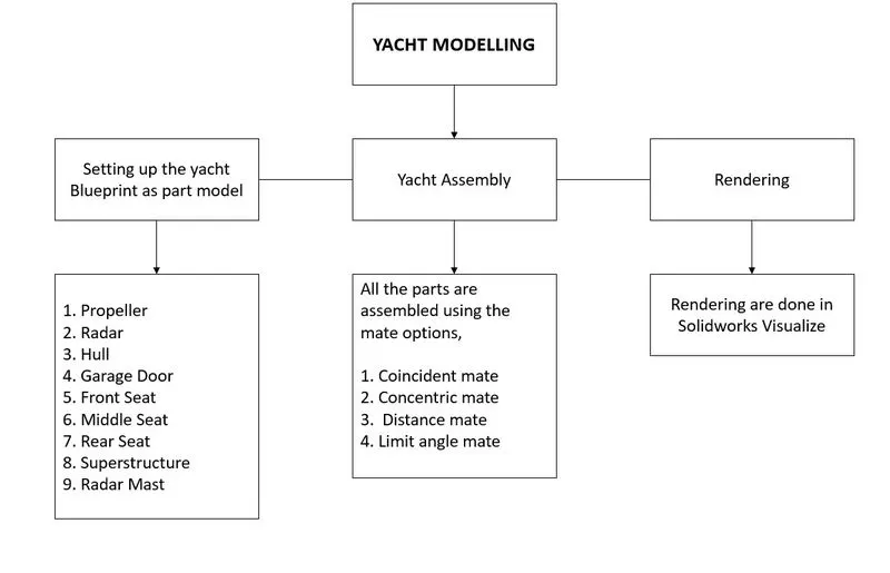
IV. Description:-
Features/Tools in the Yacht modelling,
Sketch Tools used:-
Line, Circle, Arc, Rectangle, Spline, Slot, Sketch fillet, Trim entities, Mirror entities, Offset entities, Convert entities, Geometrical constraints, Smart dimensions.
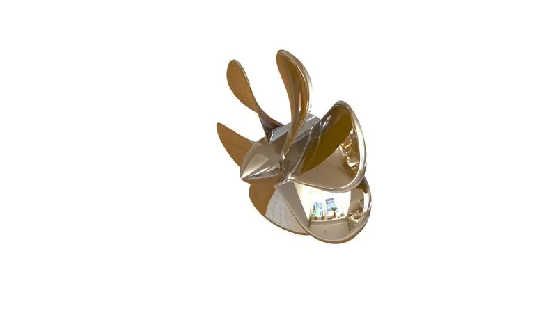
1. Propeller:-
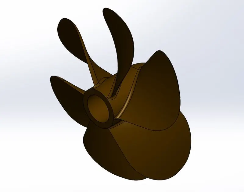
Features used:-
- Revolve - To create a solid volume by revolving a sketch about a selected axis.
- Loft - To create a solid volume joining two or more sketches created on different planes.
- Fillet - To apply radius at the edges.
- Cut Extrude - To remove material by extruding the sketch.
- Circular pattern - To create multiple instances of selected features around an axis.
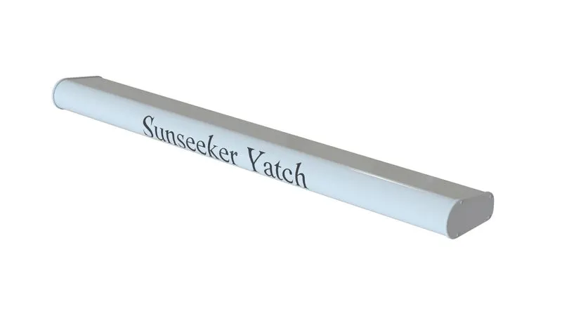
2. Radar
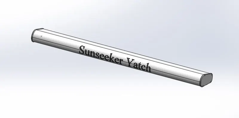
Features used:-
- Boss-Extrude - To create a solid volume by adding height to the selected sketch.
- Fillet - To apply radius at the edges.
- Cut-Extrude - To remove material by extruding the sketch.
- Mirror - To create a mirror copy of the features.
- Split line - Split the solid object into two.
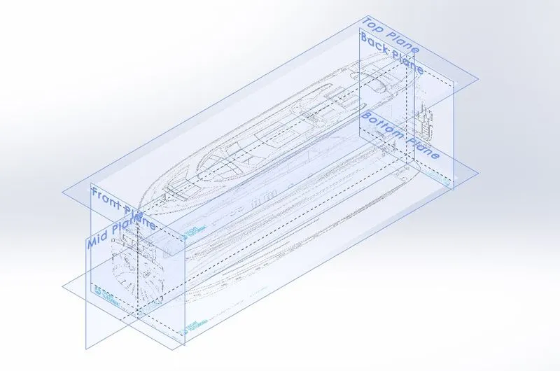
3. Blueprint
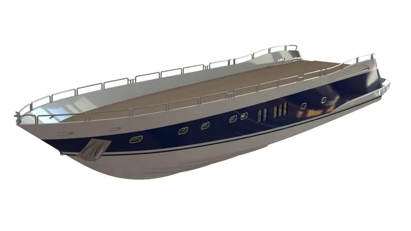
4. Hull
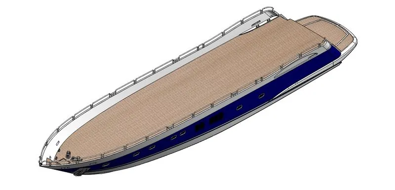
Features used:-
- Curve - To create a curve by projecting the two sketches.
- Surface Loft - To join two open or closed sections to form a surface.
- Surface Trim - To remove the desired portion of the surface by using a sketch or other surfaces.
- Surface Extrude - To extrude a close or open sketch to the specified height to form a surface.
- Surface Knit - Used to combine two or more surfaces at their common edges.
- Surface Fill - Used to fill the gap by selecting the close boundary.
- Shell - To make a solid part hollow and remove one or more faces.
- Boss Extrude - To create a solid volume by adding height to the selected sketch.
- Cut Extrude - To remove material by extruding the sketch.
- Fillet - To apply radius at the edges.
- Chamfer - To bevel the sharp edges.
- Sweep - To create a solid volume by moving a sketch along the selected path.
- Revolve - To create a solid volume by revolving a sketch about a selected axis.
- Dome - To create a concave shape of the surface.
- Linear pattern - To create a linear pattern of solid features in the modelling environment
- Mirror - To create a mirror copy of the features.
- Combine - Used to combine the two or more solid features.
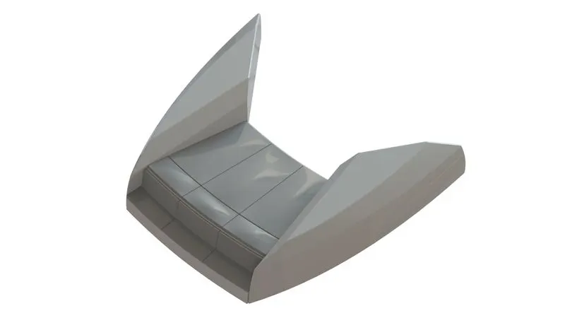
5. Garage Door
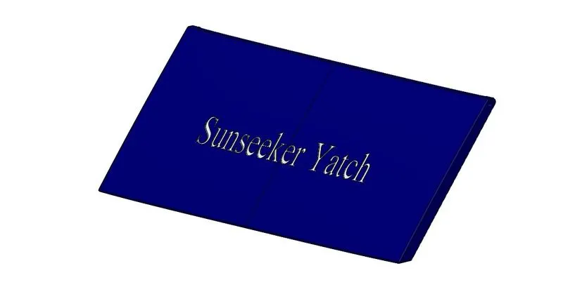
Features used:-
- Cut Extrude - To remove material by extruding the sketch.
- Shell - To make a solid part hollow and remove one or more faces.
- Fillet - To apply radius at the edges.
- Mirror - To create a mirror copy of the features.
6. Front Seat
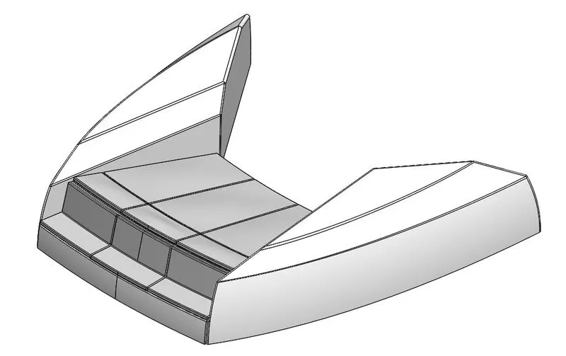
Features used:-
- Surface sweep - Used to sweep a section along the selected path to form a surface.
- Surface Extrude - To extrude a close or open sketch to the specified height to form a surface.
- Surface Trim - To remove the desired portion of the surface by using a sketch or other surfaces.
- Surface Fill - Used to fill the gap by selecting the close boundary.
- Surface Loft - To join two open or closed sections to form a surface.
- Surface knit - Used to combine two or more surfaces at their common edges.
- Chamfer - To bevel the sharp edges.
- Revolve - To create a solid volume by revolving a sketch about a selected axis.
- Cut Extrude - To remove material by extruding the sketch.
- Fillet - To apply radius at the edges.
- Mirror - To create a mirror copy of the features.
- Dome - To create a concave shape of the surface.
7. Middle Seat
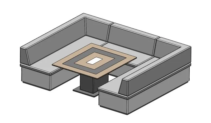
Features used:-
- Boss Extrude - To create a solid volume by adding height to the selected sketch.
- Chamfer - To bevel the sharp edges.
- Fillet - To apply radius at the edges.
- Mirror - To create a mirror copy of the features.
- Cut Extrude - To remove material by extruding the sketch.
8. Rear Seat
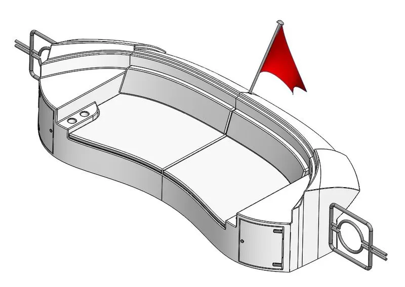
Features used:-
- Surface Sweep - Used to sweep a section along the selected path to form a surface.
- Surface Offset - Create a surface at an offset distance from the selected face or surface.
- Surface Trim - To remove the desired portion of the surface by using a sketch or other surfaces.
- Ruled Surface - Create a combination of surfaces adjoining each other.
- Surface Knit - Used to combine two or more surfaces at their common edges.
- Surface Extend - To extend the selected surface by the specified value.
- Surface Loft - To join two open or closed sections to form a surface.
- Boss Extrude - To create a solid volume by adding height to the selected sketch.
- Cut Extrude - To remove material by extruding the sketch.
- Chamfer - To bevel the sharp edges.
- Fillet - To apply radius at the edges.
- Sweep - To create a solid volume by moving a sketch along the selected path.
- Mirror - To create a mirror copy of the features.
- Revolve - To create a solid volume by revolving a sketch about a selected axis.
9. Superstructure
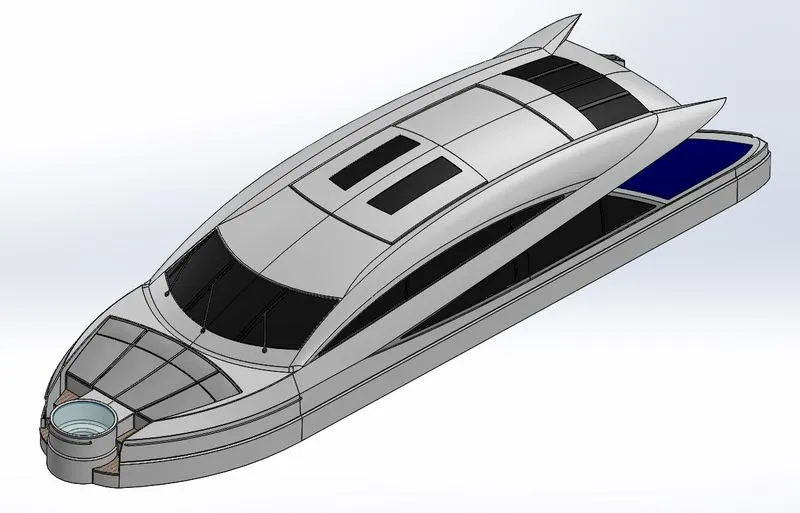
Features used:-
- Surface Extrude - To extrude a close or open sketch to the specified height to form a surface.
- Surface Sweep - Used to sweep a section along the selected path to form a surface.
- Surface Knit - Used to combine two or more surfaces at their common edges.
- Fillet - To apply radius at the edges.
- Ruled Surface - Create a combination of surfaces adjoining each other.
- Surface Trim - To remove the desired portion of the surface by using a sketch or other surfaces.
- Curve - To create a curve by projecting the two sketches.
- Surface Loft - To join two open or closed sections to form a surface.
- Surface Fill - Used to fill the gap by selecting the close boundary.
- 3D Sketch - A sketch that is not confined to one plane only.
- Surface Extend - To extend the selected surface by the specified value.
- Boss Extrude - To create a solid volume by adding height to the selected sketch.
- Cut Extrude - To remove material by extruding the sketch.
- Surface Offset - Create a surface at an offset distance from the selected face or surface.
- Thicken - Used to add thickness to the surface.
- Dome - To create a concave shape of the surface.
- Sweep - To create a solid volume by moving a sketch along the selected path.
- Split Line -
- Mirror - To create a mirror copy of the features.
- Chamfer - To bevel the sharp edges.
10. Radarmast
Features used:-
- Boss Extrude - To create a solid volume by adding height to the selected sketch.
- Fillet - To apply radius at the edges.
- Revolve - To create a solid volume by revolving a sketch about a selected axis.
- Sweep - To create a solid volume by moving a sketch along the selected path.
- Mirror - To create a mirror copy of the features.
- Curve - To create a curve by projecting the two sketches.
- Chamfer - To bevel the sharp edges.
- Dome - To create a concave shape of the surface.
- Shell - To make a solid part hollow and remove one or more faces.
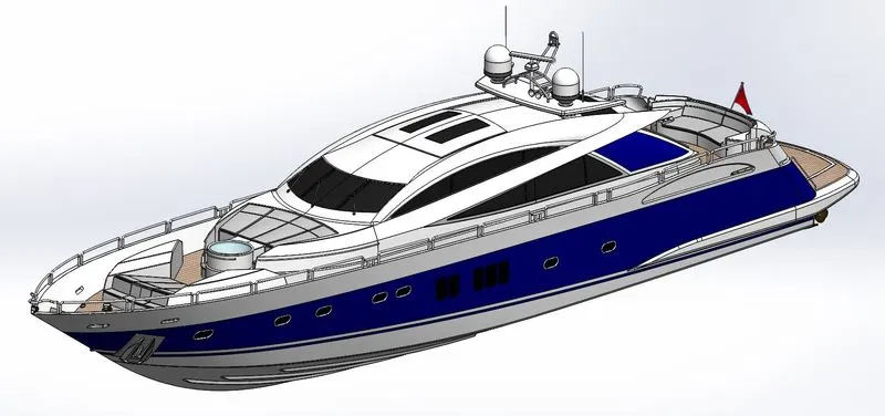
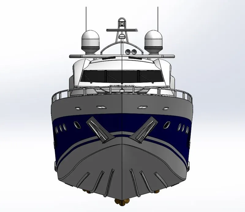
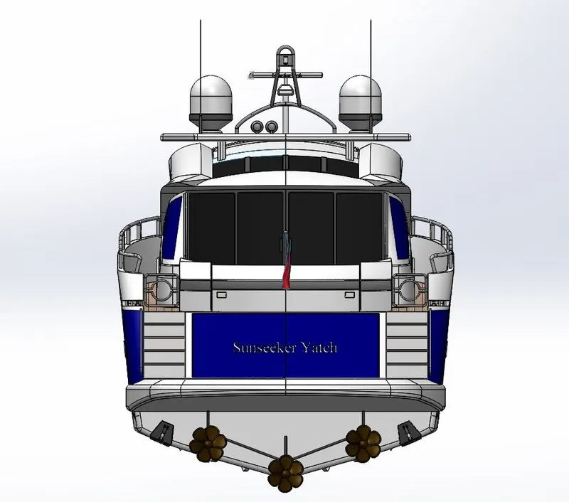
V. Yacht Assembly:-
Features Used:-
- Coincident mate
- Concentric mate
- Distance mate
- Limit angle mate
Isometric View:-
Front View:-
Rear View:-
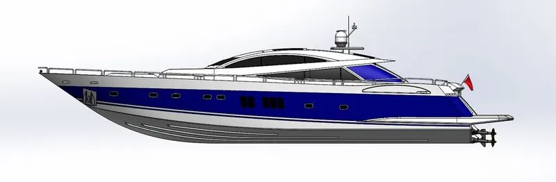
Side View:-
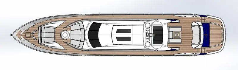
Top View:-
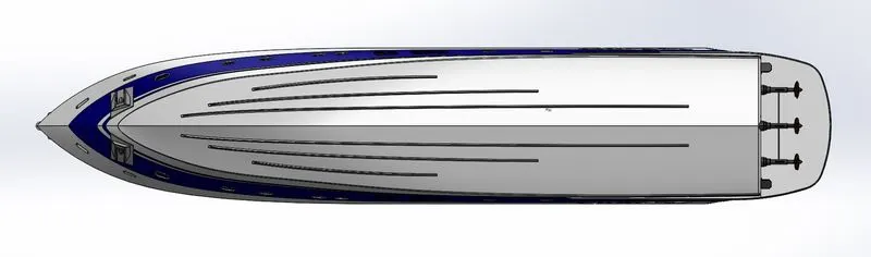
Bottom View:-
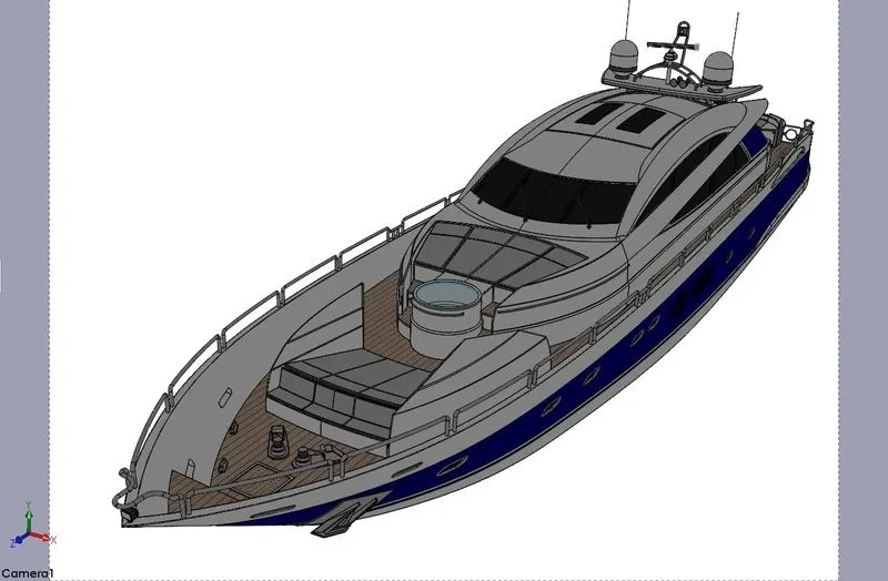
Camera Setup View:-

VI. Rendering Image:-
I. Part Model
1. Propeller
2. Radar
3. Hull
4. Garage Door
5. Front Seat
6. Middle Seat
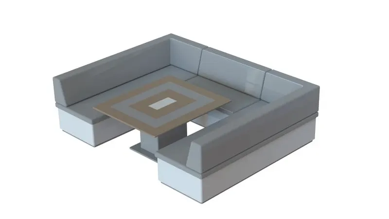
7. Rear Seat
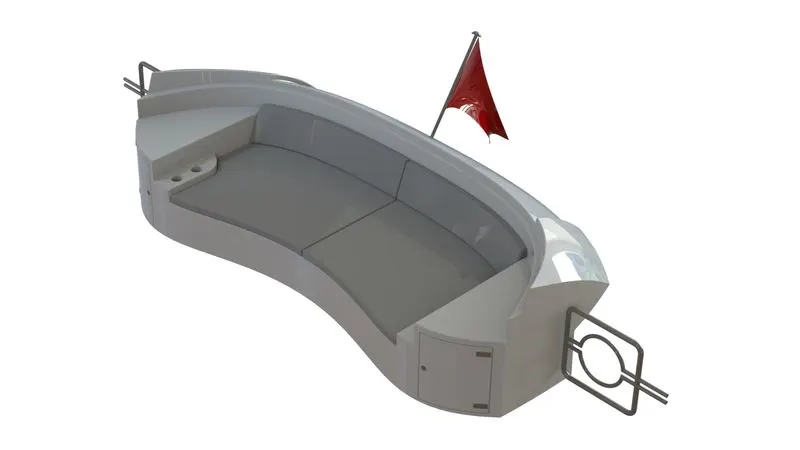
8. Superstructure
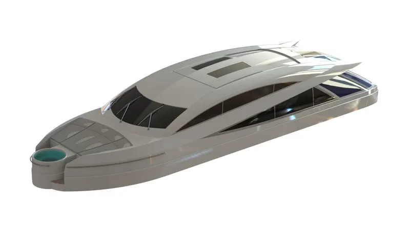
9. Radarmast
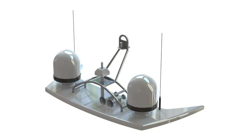
II. Assembly Model
VII. Conclusion:-
From this project, I learnt Surface and Solid modelling with a yacht model and rendered the model using Solidworks Visualization.
Link:-