Week 3 - External flow simulation over an Ahmed body.
EXTERNAL FLOW SIMULATION OVER AN AHMED BODY
Aim:-
To simulate the external flow over an Ahmed body. The drag coefficient should be around 0.33 at a velocity of 25m/s.
Introduction:-
1. Ahmed body and its importance:
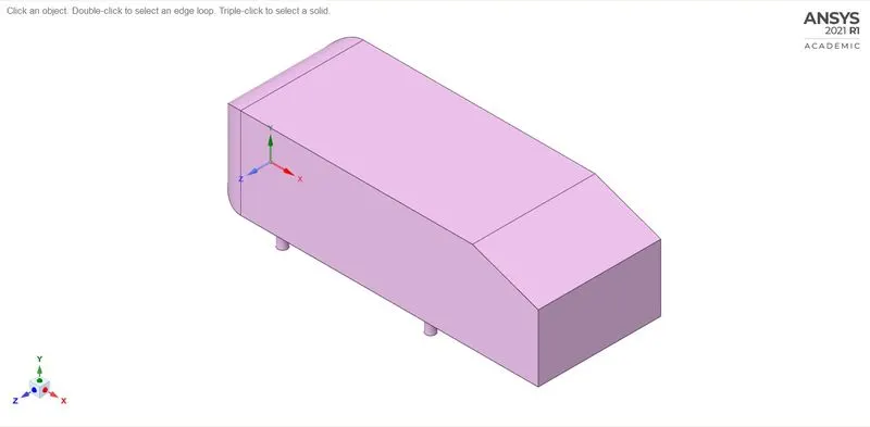
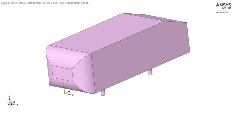
The Ahmed body is a generic car body (a simplified vehicle model). The airflow around the Ahmed body captures the essential flow features around an automobile and was first defined and characterized in the experimental work of Ahmed body. It is a very simple shape, Ahmed body allows us to capture characteristics features that are relevant to bodies in the automobile industry.
The Ahmed body is a simplified car, used in the automotive field to investigate the flow analysis and find the wake flow around the body. Ahmed body is made up of round front part, a movable z slant plane in the rear of the body to study the detachment phenomena at different angles, and a rectangular box which link the front part and the rear slant plane.
This model is also used to describe the turbulent flow around a car-like geometry. Once the numerical model is validated, it is used to design a new model of the car.
Ahmed body model:
2. Reason for the negative pressure in the wake region.
When the air is moving over the vehicle the air is separated at the rear end of the vehicle, that low-pressure region is known as the wake region.
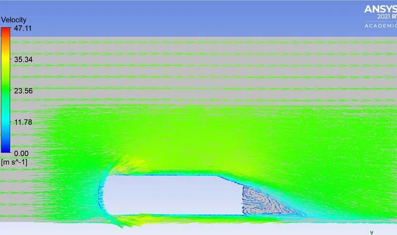
The recirculating flow in the wake region having negative pressure. which is occurred by the pressure drag. The pressure drag is a combination of two forces that work against the acceleration of your car that is frontal pressure and rear suction. The negative pressure is caused mainly because of the formation of turbulent eddies which is actually the consequence of flow separation.
3.Significance of Point of separation.
A fluid acts much the same way when forced to flow over a curved surface at high velocities. A fluid follows the front portion of the curved surface with no problem, but it has difficulty remaining attached to the surface on the backside. At sufficiently high velocities, the fluid stream detaches itself from the surface of the body. This is called flow separation.
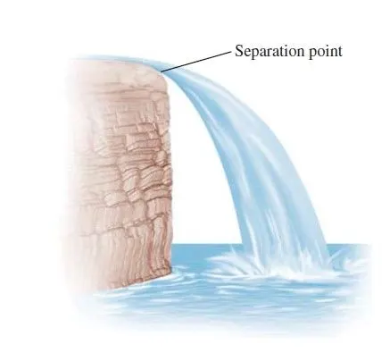
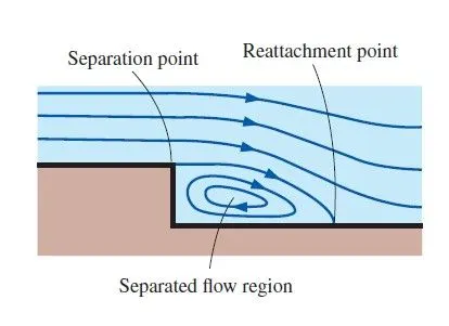
a. Flow separation in a waterfall b. Flow separation over a backward-facing step
Flow can be separated from a surface even if it is fully submerged in a liquid or immersed in a gas. The location of the separation point depends on several factor such as the reynolds number, the surface roughness, and the level of fluctuation in the free stream, and it is usually difficult to predict exactly where the separation will occur unless there are sharp corners or abrupt changes in the shape of the solid surface.
When a fluid separates from a body, it forms a separated region between the body and the fluid stream. The low-pressure region behind the body where recirculating and backflow occur is called the separated region. The larger the separated region, the larger the pressure drag. The region of flow trailing the body where the effects of the body on velocity are felt is called the wake.
An important consequence of flow separation is the formation and shedding of circulating fluid structures, called vortices, in the wake region. The periodic generation of these vortices downstream is referred to as vortex shedding.
Simulation process (ANSYS Fluent):-
Geometry (SpaceClaim):-
To simulate the Ahmed body first to create the wind tunnel to measure the wake region and the drag and lift coefiicient.
For a wind tunnel to create a two enclosures around the Ahmed body.
Enclosure - 1:-
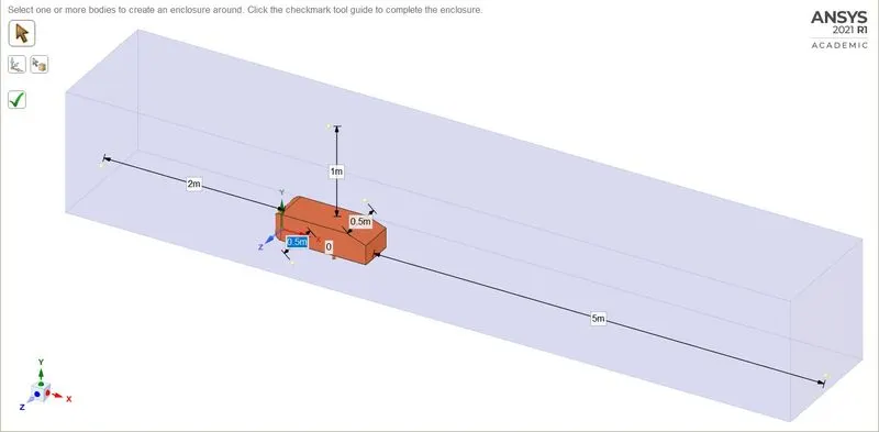
Enclosure - 2:-
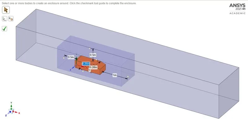
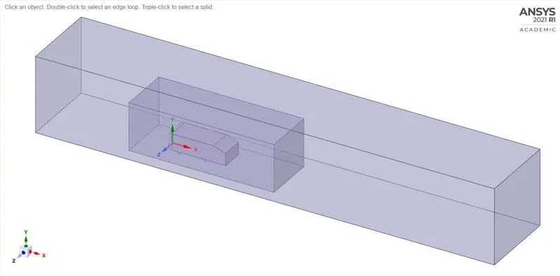
After creating the enclosure the Ahmed body has been split into two by the 'split body' command. To save the number of cells and get results faster.
Before Split the Ahmed body:-
After Split the Ahmed body:-
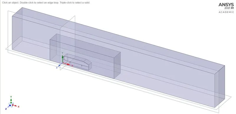
After splitting the body hides the object and suppress for physics.
Interference region:-
The two enclosures are merge that will give coarse mesh that is called the interference region.
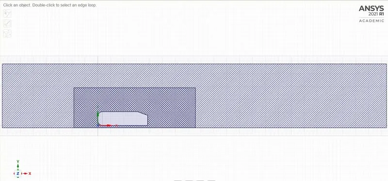
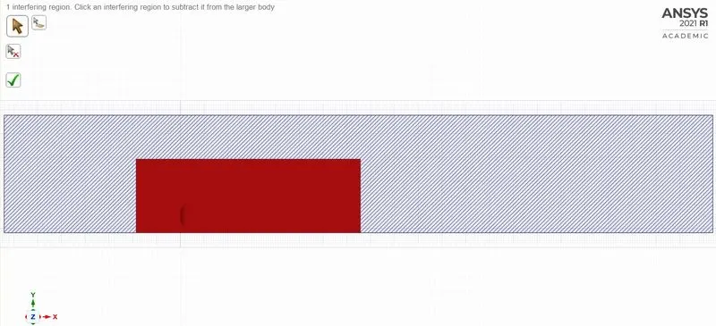
After Interference:-
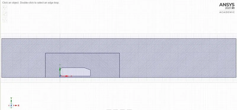
After subtracting the interference region from the large body share the topology in the 'spaceclaim'.
In the analysis, the grid independency test will be performed up to when the drag coefficient reaches 0.33. The different cases will be simulated for refining the mesh to obtain those values.
Case -1:-
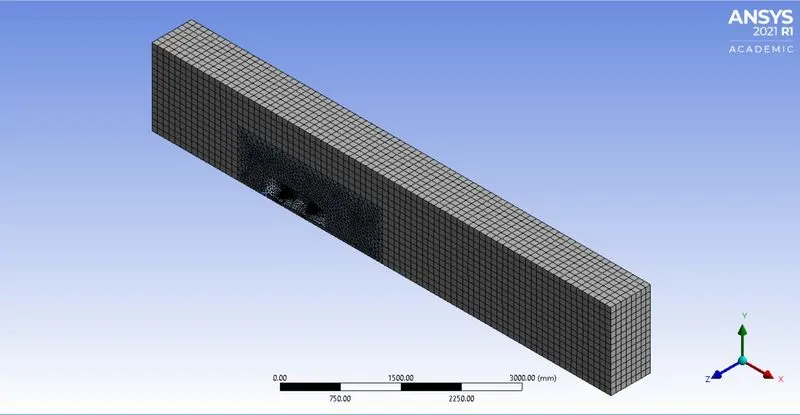
Meshing:-
First the named selection for inlet, outlet, symmetry, and car-wall.
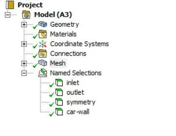
1. The outer enclosure or wind tunnel should be in the multizone method.
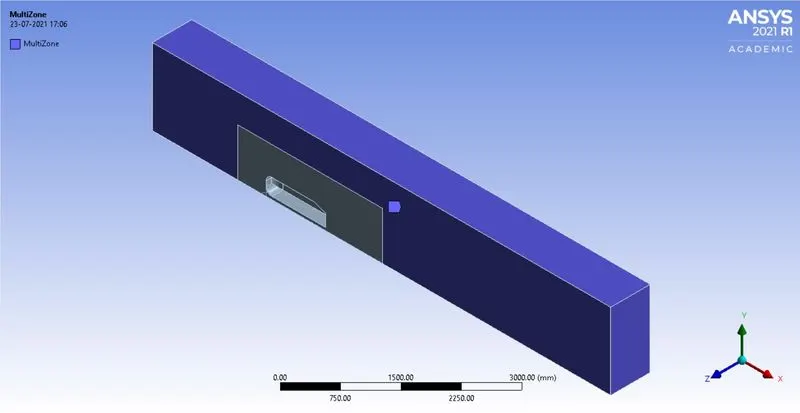
Element Size = 100 mm.
2. The inner enclosure should be in body sizing.
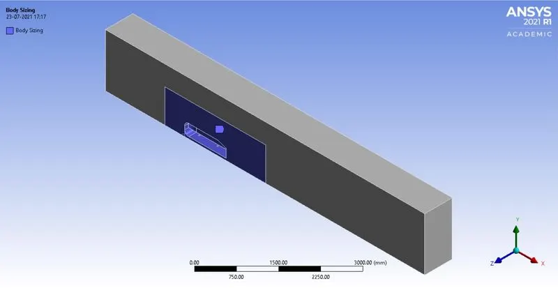
Element Size = 50 mm.
3. The Cylinder shape of the Ahmed body (wheel) is sizing as the face.
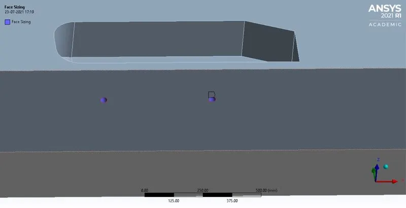
Element size = 5 mm
4. Inflation layer:-
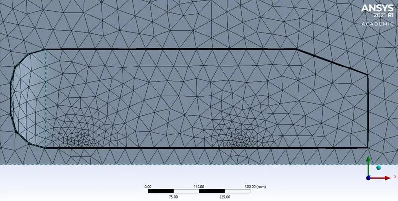
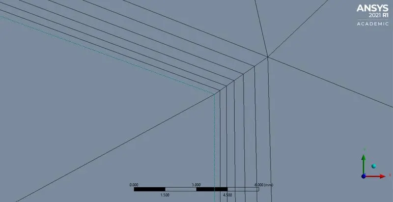
- First layer Height = 0.5 mm
- Maximum layer = 6
- Growth rate = 1.2
- Nodes = 31679
- No.of Element = 95845
Fluent (Setup & Solution):-
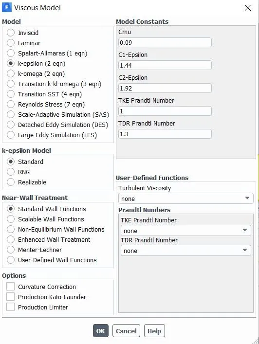
Turbulence model:-
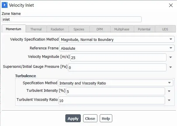
Boundary Conditions:-
Inlet = 25m/s.
Reference Value:-
The reference value is taken from the inlet region.
- Area = 0.065741`m^2`
- Length = 1.044m
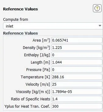
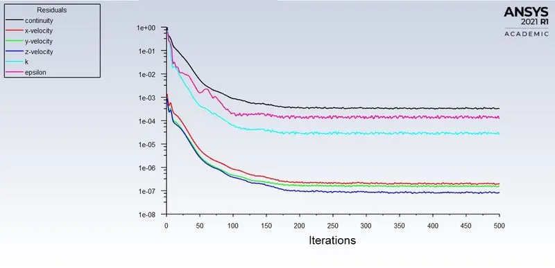
After setting up the value Initialize them for a Hybrid solution. And run for 500 iterations.
Residuals graph:-
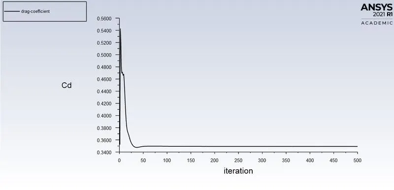
Drag Coefficient:-
Lift Coefiicient:-
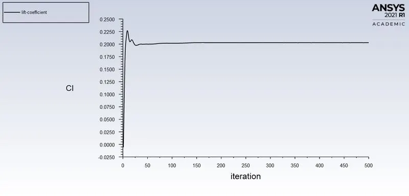
- Drag Coefficient = 0.34926767
- Lift Coefficient = 0.20278573
Result (Post-Processing):-
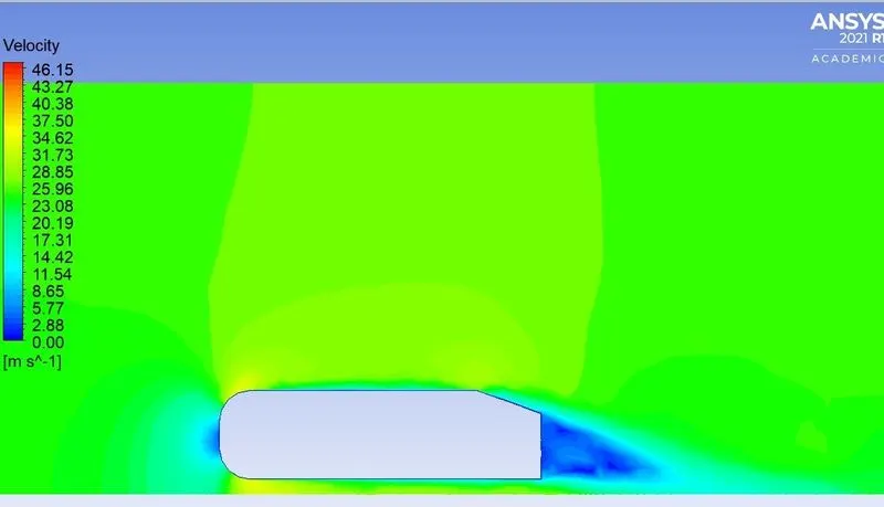
Velocity Plot:-
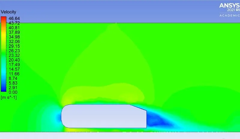
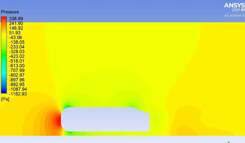
Pressure Plot:-
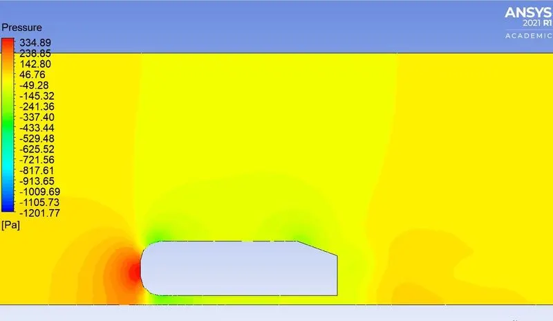
Vector Plot:-
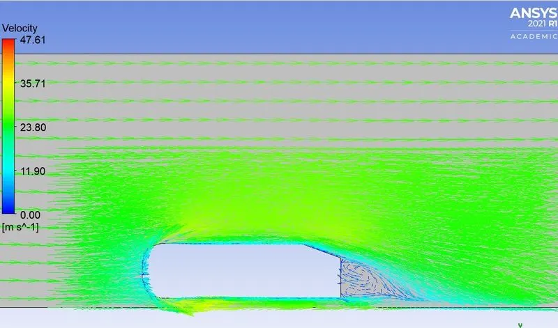
Case -2:-
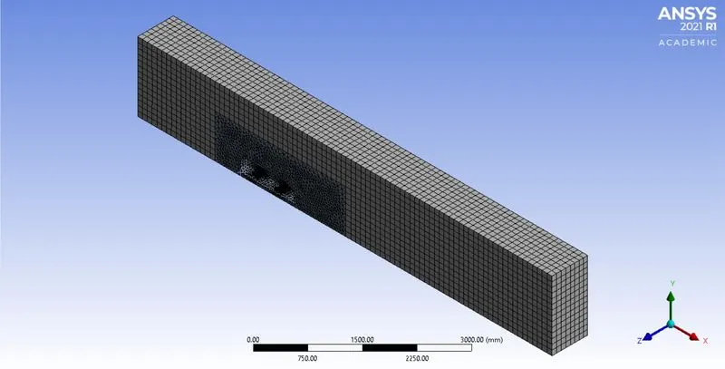
Meshing:-
Named the selection for inlet, outlet, symmetry, and car-wall.
1. The outer enclosure or wind tunnel should be in the multizone method.
Element Size = 95 mm.
2. The inner enclosure should be in body sizing.
Element Size = 48 mm.
3. The Cylinder shape of the Ahmed body (wheel) is sizing as the face.
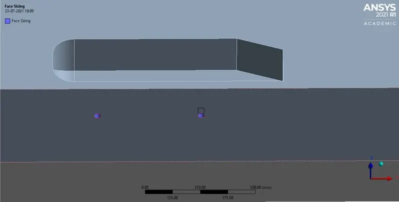
Element size = 5 mm
4. Inflation layer:-
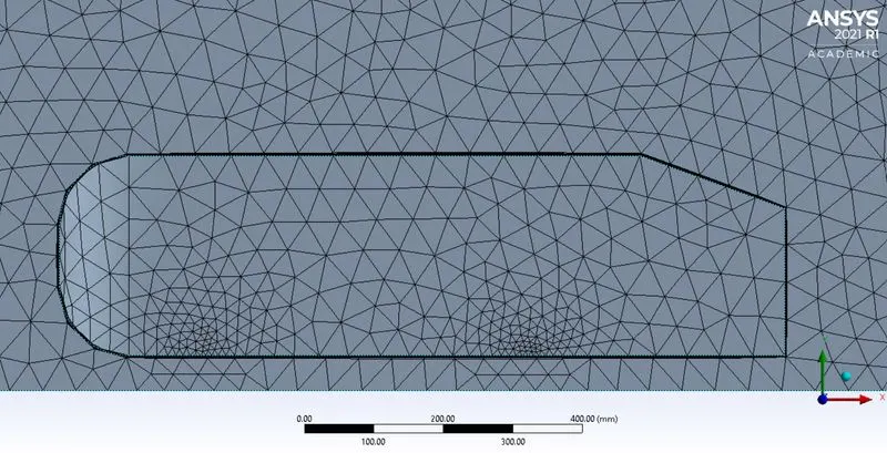
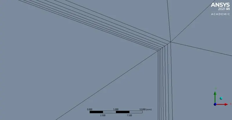
- First layer Height = 0.45 mm
- Maximum layer = 6
- Growth rate = 1.2
- Nodes = 33520
- No.of Element = 103632
Fluent (Setup & Solution):-
Turbulence model:-
Boundary Conditions:-
Inlet = 25m/s.
Reference Value:-
The reference value is taken from the inlet region.
- Area = 0.065741`m^2`
- Length = 1.044m
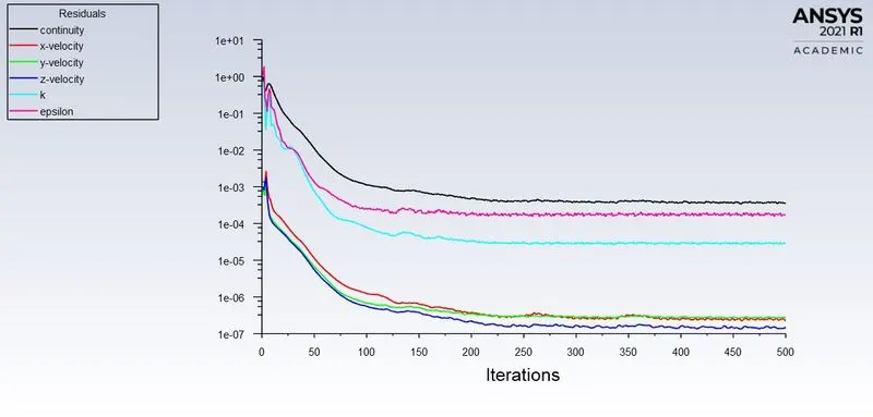
After setting up the value Initialize them for a Hybrid solution. And run for 500 iterations.
Residuals graph:-
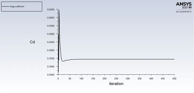
Drag Coefficient:-
Lift Coefficient:-
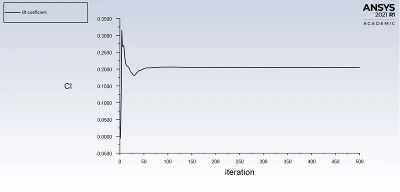
- Drag Coefficient = 0.34379775
- Lift Coefficient = 0.20463549
Result (Post-Processing):-
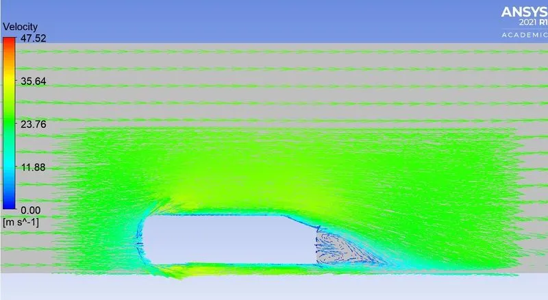
Velocity Plot:-
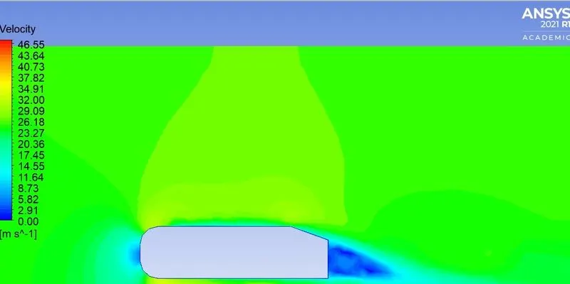
Pressure Plot:-
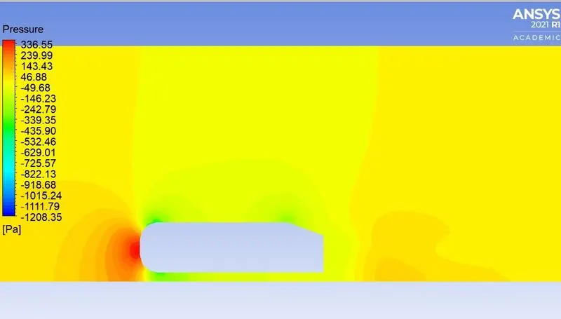
Vector Plot:-
Case -3:-
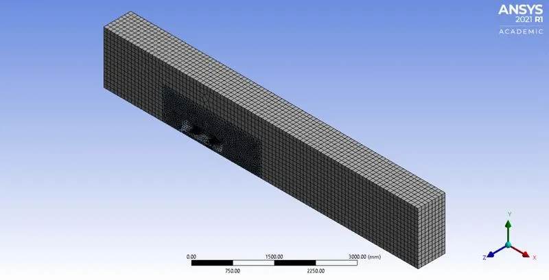
Meshing:-
Named the selection for inlet, outlet, symmetry, and car-wall.
1. The outer enclosure or wind tunnel should be in the multizone method.
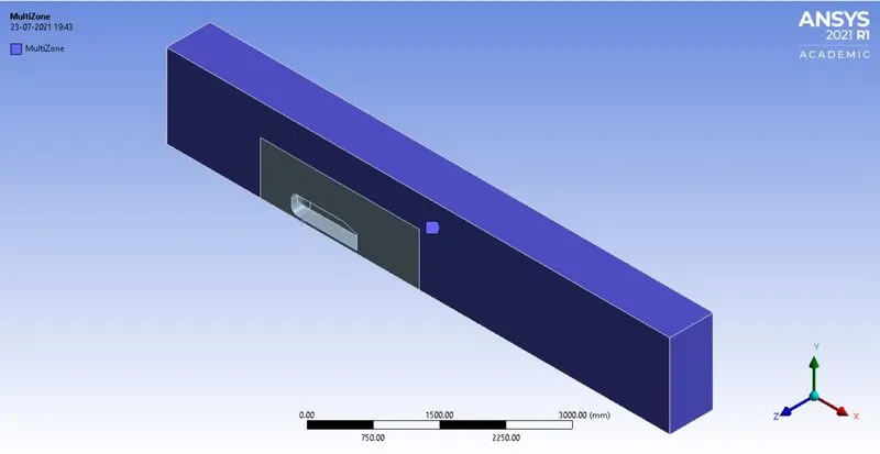
Element Size = 90 mm.
2. The inner enclosure should be in body sizing.
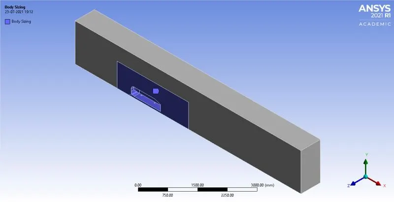
Element Size = 45 mm.
3. The Cylinder shape of the Ahmed body (wheel) is sizing as the face.
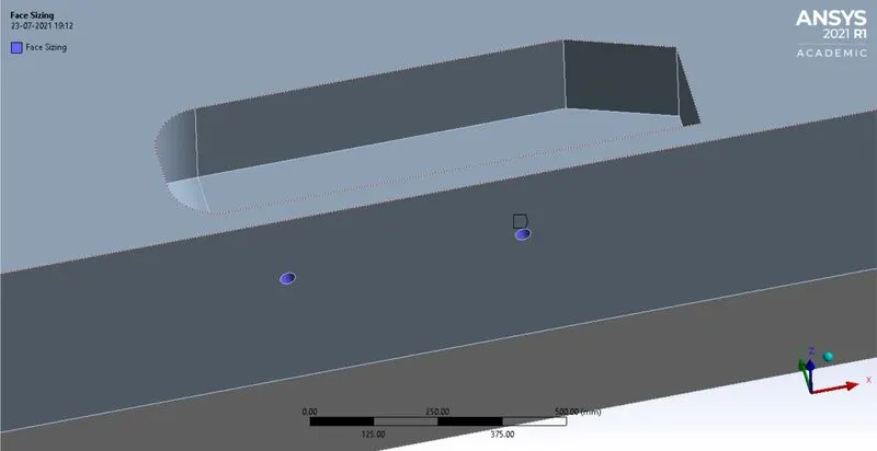
Element size = 5 mm
4. Inflation layer:-
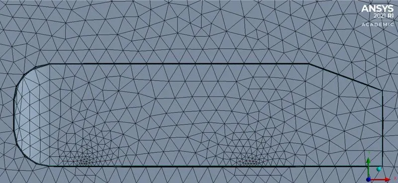
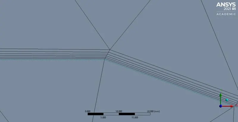
- First layer Height = 0.4 mm
- Maximum layer = 6
- Growth rate = 1.2
- Nodes = 37586
- No.of Element = 119348
Fluent (Setup & Solution):-
Turbulence model:-
Boundary Conditions:-
Inlet = 25m/s.
Reference Value:-
The reference value is taken from the inlet region.
- Area = 0.065741`m^2`
- Length = 1.044m
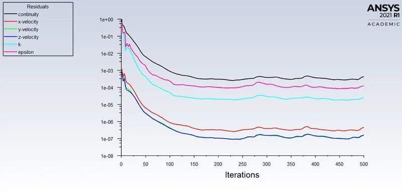
After setting up the value Initialize them for a Hybrid solution. And run for 500 iterations.
Residuals graph:-
Drag Coefficient:-

Lift Coefficient:-
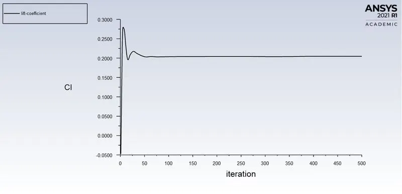
- Drag Coefficient = 0.33177572
- Lift Coefficient = 0.20473091
Result (Post-Processing):-
Velocity Plot:-
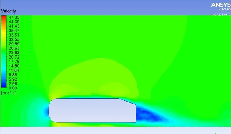
Pressure Plot:-
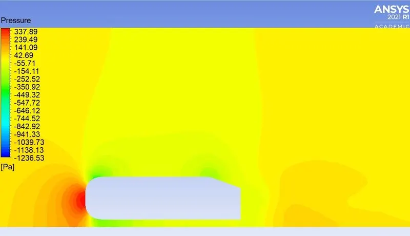
Vector Plot:-
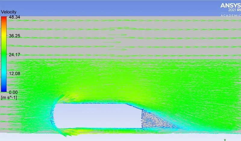
Case -4:-
Meshing:-
Named the selection for inlet, outlet, symmetry, and car-wall.
1. The outer enclosure or wind tunnel should be in the multizone method.
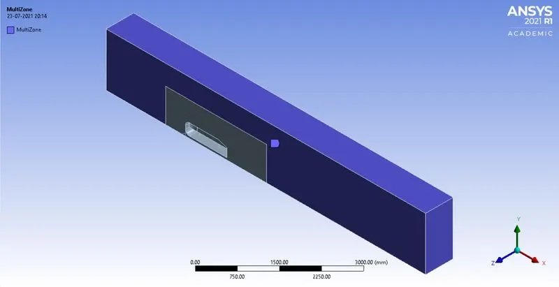
Element Size = 85 mm.
2. The inner enclosure should be in body sizing.
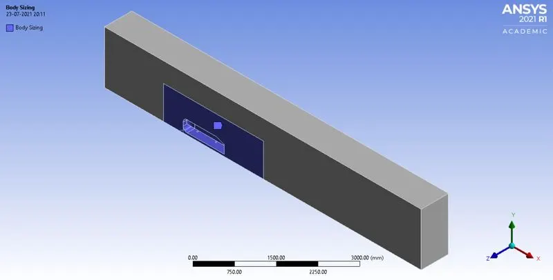
Element Size = 42 mm.
3. The Cylinder shape of the Ahmed body (Wheel) is sizing as the face.
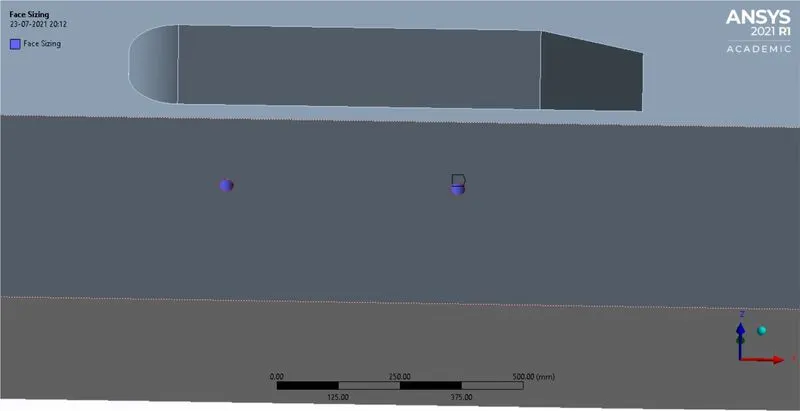
Element size = 5 mm
4. Inflation layer:-
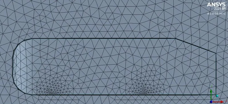
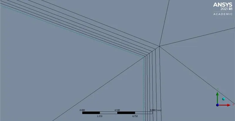
- First layer Height = 0.38 mm
- Maximum layer = 6
- Growth rate = 1.2
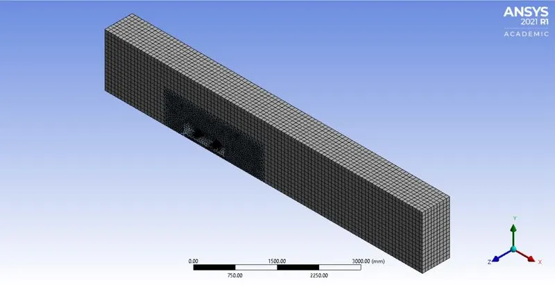
- Nodes = 43612
- No.of Element = 139331
Fluent (Setup & Solution):-
Turbulence model:-
Boundary Conditions:-
Inlet = 25m/s.
Reference Value:-
The reference value is taken from the inlet region.
- Area = 0.065741`m^2`
- Length = 1.044m
After setting up the value Initialize them for a Hybrid solution. And run for 500 iterations.
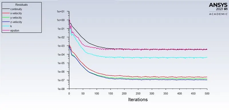
Residuals graph:-
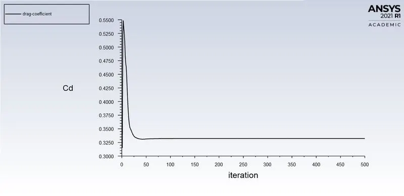
Drag Coefficient:-
Lift Coefficient:-
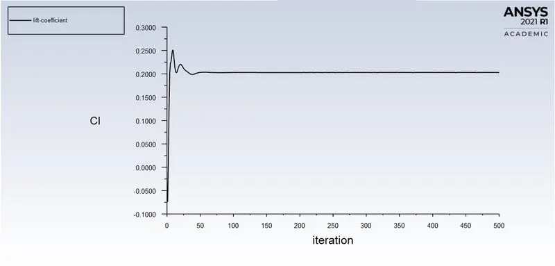
- Drag Coefficient = 0.33229254
- Lift Coefficient = 0.20289053
Result (Post-Processing):-
Velocity Plot:-
Pressure Plot:-
Vector Plot:-
Grid Independence Test:-
Case First Layer Height Elements Drag Coefficient Lift Coefficient
I 0.5 mm 95845 0.34926767 0.20278573
II 0.45 mm 103632 0.34379775 0.20463549
III 0.4 mm 119348 0.33177572 0.20473091
IV 0.38 mm 139331 0.33229254 0.20289053
Conclusion:-
- From the above simulation result and grid independence if we refine meshing based upon the Y+ value the coefficient of drag will be obtained as required.
- The Y+ value below 30 drag coefficient should be near 0.33.
- If the drag coefficient will reduce the lift coefficient will be increased.
- If we reduce the flow separation and thus reduce pressure drag.
- Viscous and rotational effects are the most significant in the boundary layer, the separated region, and the wake.