Week 10 - Simulating Combustion of Natural Gas.
SIMULATING THE COMBUSTION OF NATURAL GAS
Aim:-
To perform the combustion simulation on a combustor model and plot the variation of the mass fraction of different species and adding water into the fuel to measure the NOx and Soot formation.
Objective:-
Part-I
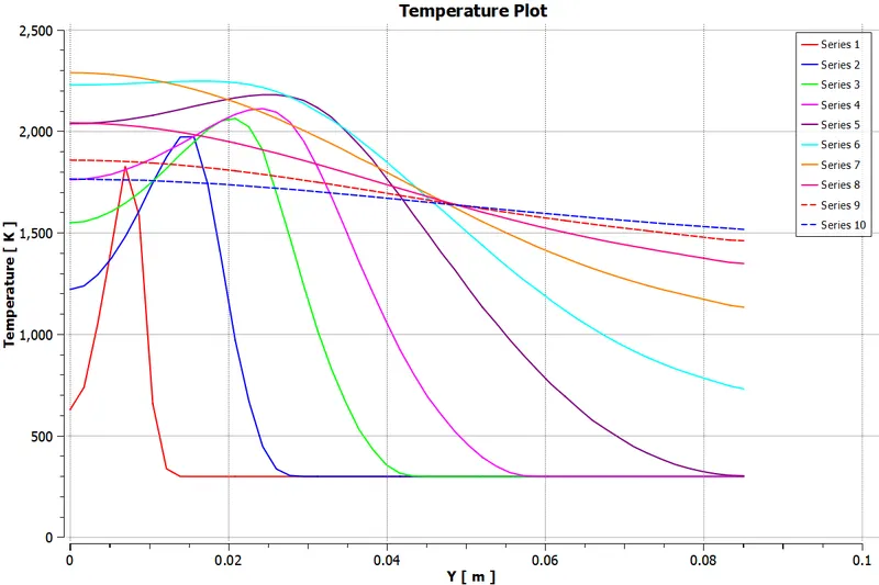
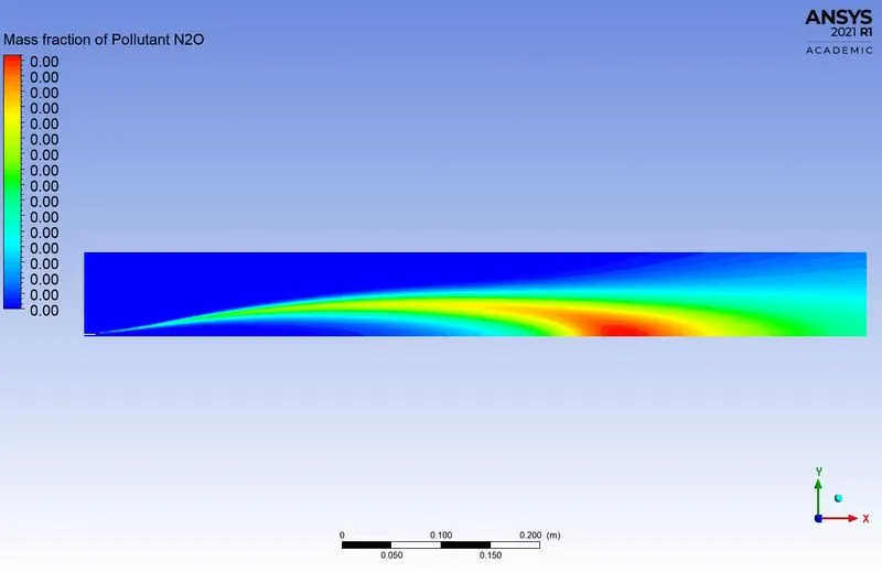
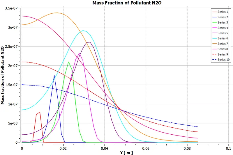
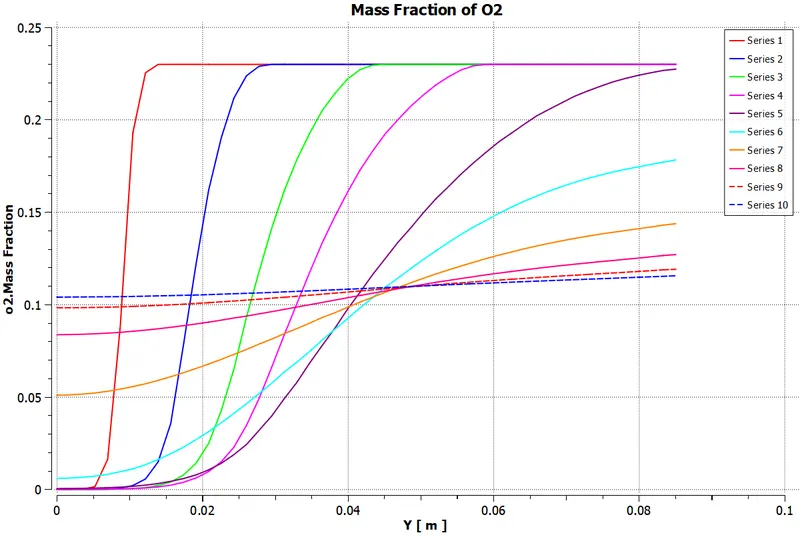
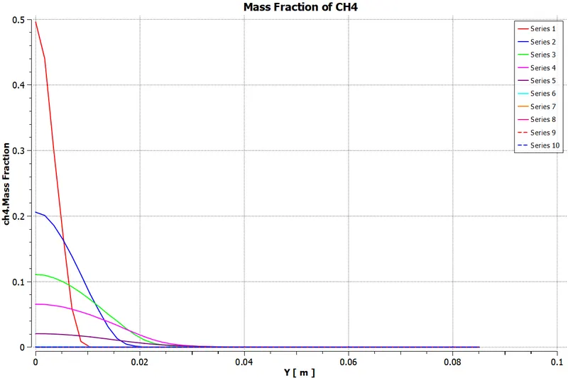
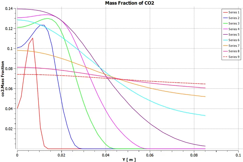
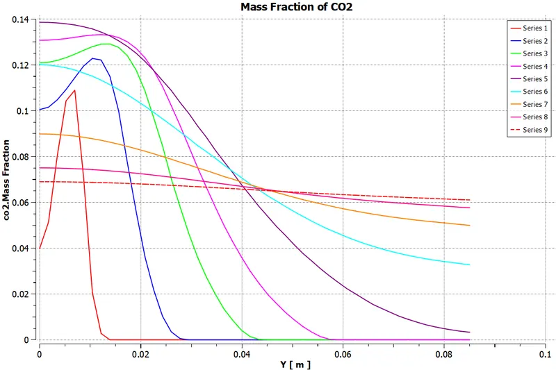
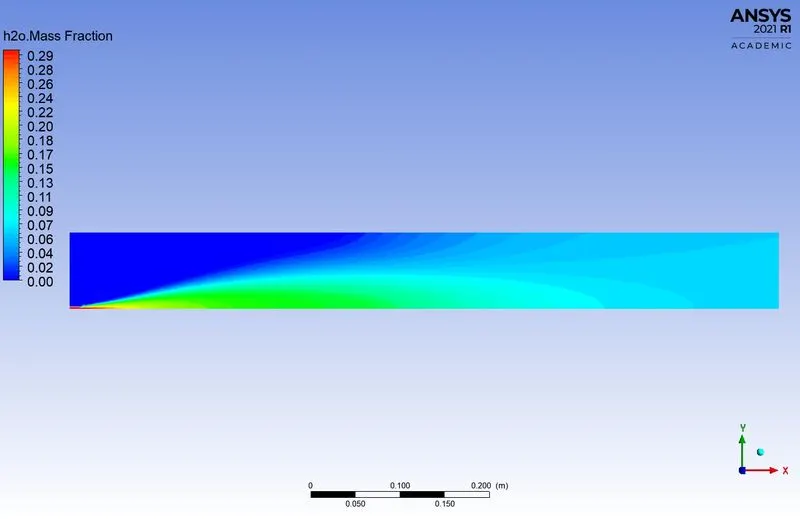
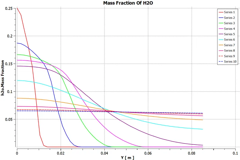
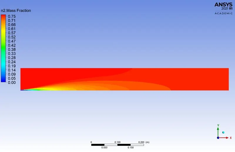
Perform a combustion simulation on the combustor model and plot the variation of the mass fraction of the different species in the simulation using line probes at different locations of the combustor. To plot for CO2, H2O, CH4, N2, O2, NOx emission & soot formation.
Part-II
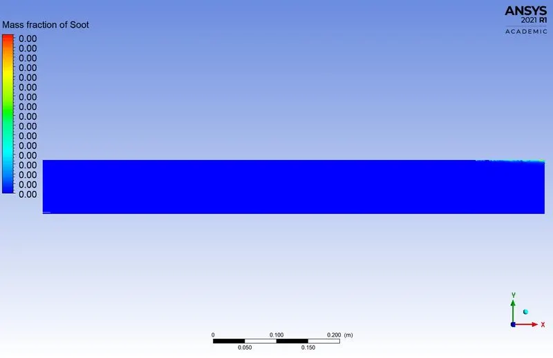
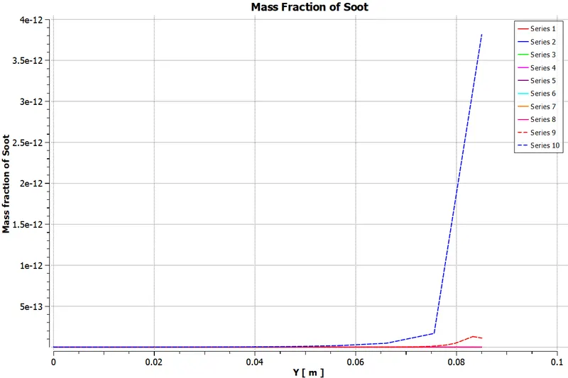
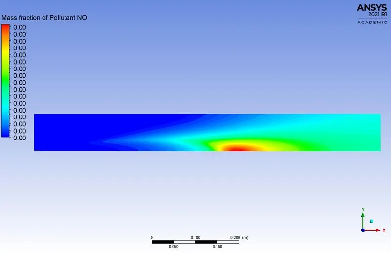
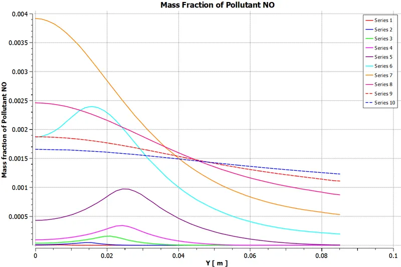
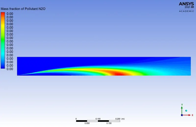
As you must have observed from the above simulation, the NOx and soot are getting formed at the outlet of the combustor. Such formation has a harmful effect on the environment and humans. The stringent government norms also demand the least formation of NOx and soot to satisfy those requirements, you need to check the effect of adding the water in the fuel.
In this part, you need to add the water content in the fuel from 5% to 30% by mole and observe the effect of it on the results. It is necessary to provide line plots and contours to prove your claim.
Introduction And Theory:-
A. Combustion:-
Combustion, or burning, is a high-temperature exothermic redox chemical reaction between a fuel and an oxidant, usually, atmospheric oxygen, that produces oxidized, often gaseous products, in a mixture termed as smoke. Combustion does not always result in fire, because a flame is only visible when a substance undergoing combustion vapourise, but when it does, a flame is a characteristic indicator of the reaction. While the activation energy must be overcome to initiate combustion, the heat from a flame may provide enough energy to make the reaction self-sustaining.
B. Possible Type of Combustion Simulation:-
1. Based on mixing
- Non-Premixed combustion (Direct injection, Late injection)
- Premixed combustion (Carburetor)
- Partially premixed.
2. Based on Phase.
- Fluid phase (Volumetric reaction)
- Wall (Surface Reaction)
- Particles (Surface reaction)
- Porus Region (Example: After treatment system)
C. Combustion Source Calculation:-
1. Finite Rate Chemistry
- Accurate but slow
2. Mixing Based Models
- The Eddy dissipation model
- Fast but requires user experience.
3. Finite Rate Eddy Dissipation model
- Combustion of both finite rate chemistry and eddy dissipation model.
- Used to prevent instantaneous burning (mixed is burnt problem).
D. Combustion Reaction:-
Stoichiometric equation,
`CH4+ar(O_2+3.76N_2) -> aCO_2+bH_2O+ cN_2`
1. `a = 1`
2. `2b = 4 =>b=2`
3. `2ar = 2a+b`
`ar =(2(1)+(2))/2`
`ar = 2`
- Fuel = 1 mole of `CH_4`
- Air = 2 Mole `O_2`+ 7.52 moles `N_2`
Mole fraction:
`"Mole Fraction" = "Moles of solute"/("Total moles of solution")`
`O_2 = (2)/(2+7.52) = 0.21`
`N_2 = 7.52/(2+7.52) = 0.79`
Mass Fraction:
`"Mass Fraction" = " Mass of the mixture"/("Total mass of the mixture")`
`O_2 = (0.21xx 16)/((0.21xx16)+(0.79xx14)) =0.23`
`N_2 = (0.79xx14)/((0.21xx16)+(0.79xx14)) = 0.77`
*****************************************************************************************
Simulation Process
SpaceClaim (Geometry):-
- In SpaceClaim, the 2D combustor model is extracted from the 3D model. Because the given model is in 3D and also 3D model simulation take much more time to solve and the academic version of Ansys have the meshing limit.
- So that the 2D axisymmetry model is taken for the simulation.
- The 3D geometry model has been split in the axis of the XY plane.
- And split in the axis of the XZ plane using the "Split Body" command.
- The Required selected area is copied and pasted in a new design window.
- The 3 surface regions are combined into one surface using the "Combine" tool.
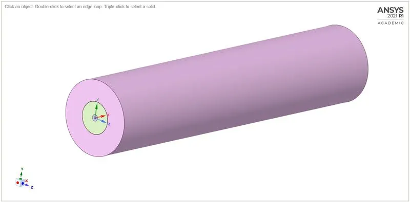
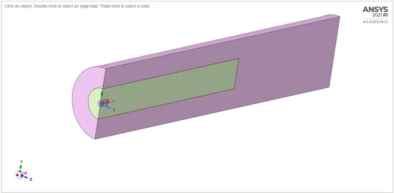
Fig(a). 3D Combustor Model Fig(b). Split in XY Plane
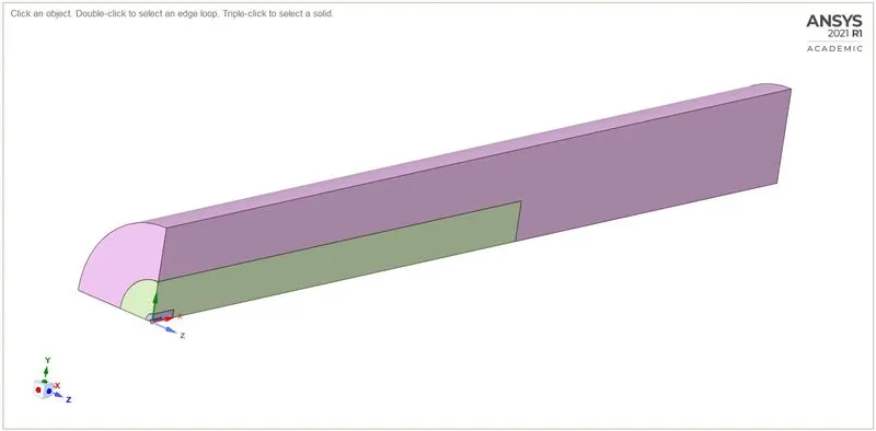
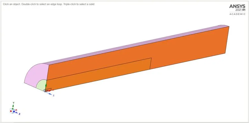
Fig(c). Split in XZ Plane Fig(d). Selection of the required region
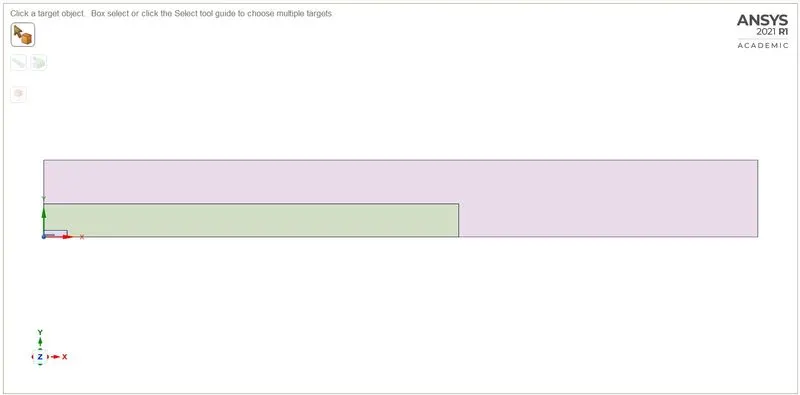
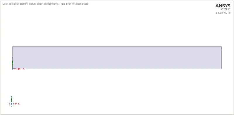
Fig(e). Extracted 2D Surface Fig(f). Surface after Combined
Meshing:-
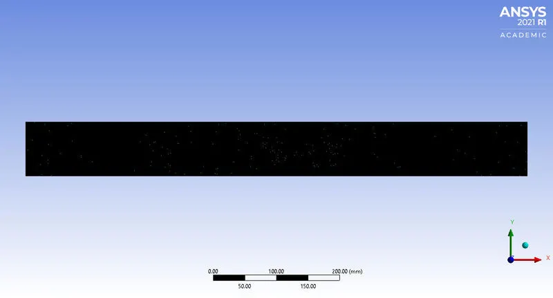
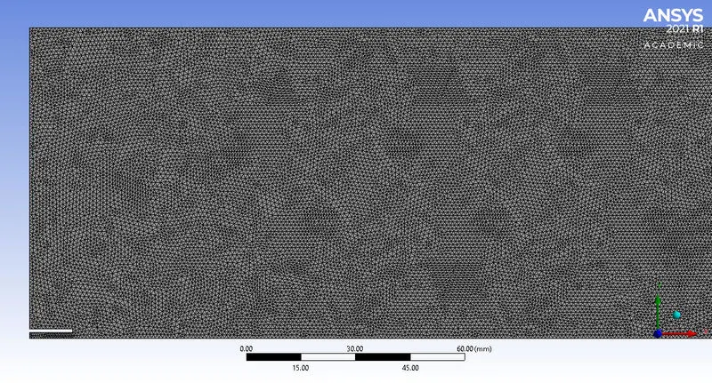
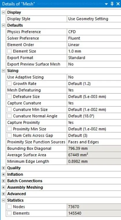
- Element Size = 1mm
- Method = All Triangle Method
- Capture Proximity = yes
- Number of cells across gaps = 3
- Nodes = 73670
- No. of Elements = 145540
Named Selection:-
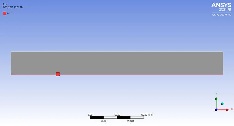
Axis:-
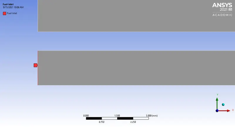
Fuel-Inlet:-
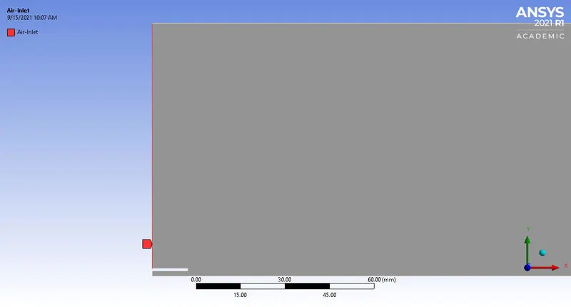
Air-Inlet:-
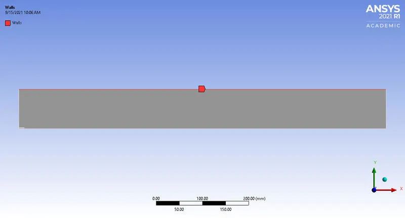
Wall:-
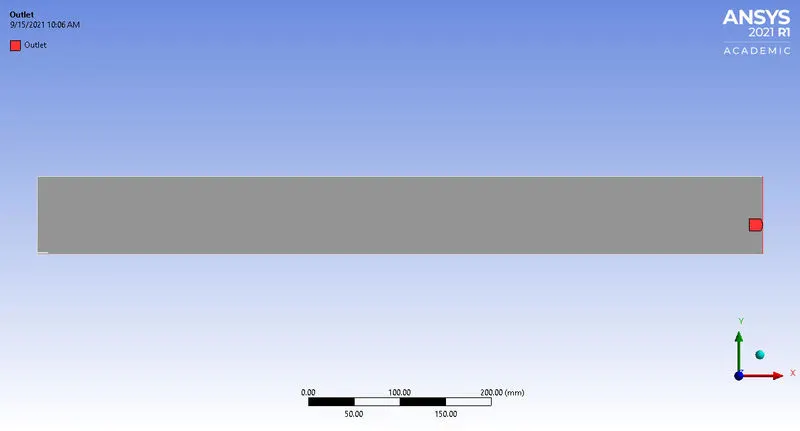
Outlet:-
Fluent Setup and Solving:-
1. Solver
- Type = Pressure based
- Velocity Formulation = Absolute
- Time = Steady
- 2D Space = Axisymmetric
2. Enable Energy equation.
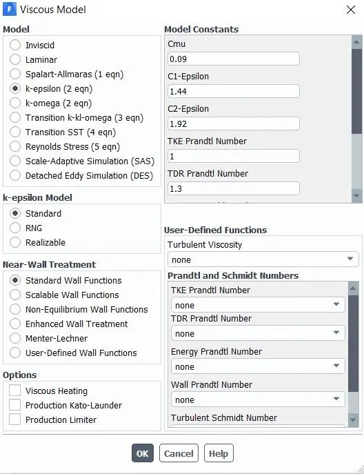
3. Viscous Model = K-epsilon, Standard, Standard wall function.
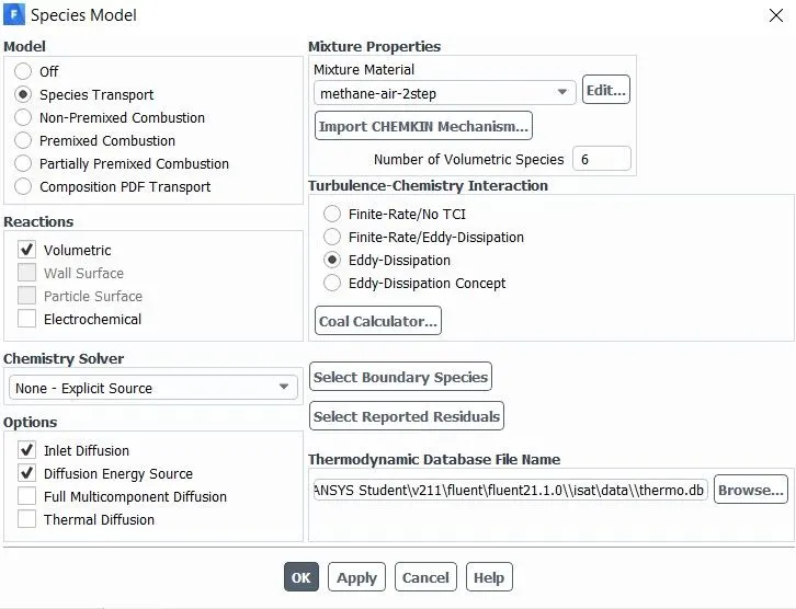
4. Species
- Model = Species Transport
- Reaction = Volumetric
- Options = Inlet diffusion,Diffusion Energy Source
- Mixture material = methane-air-2step
- Turbulence-chemistry interaction = Eddy dissipation model
5. NOx Model

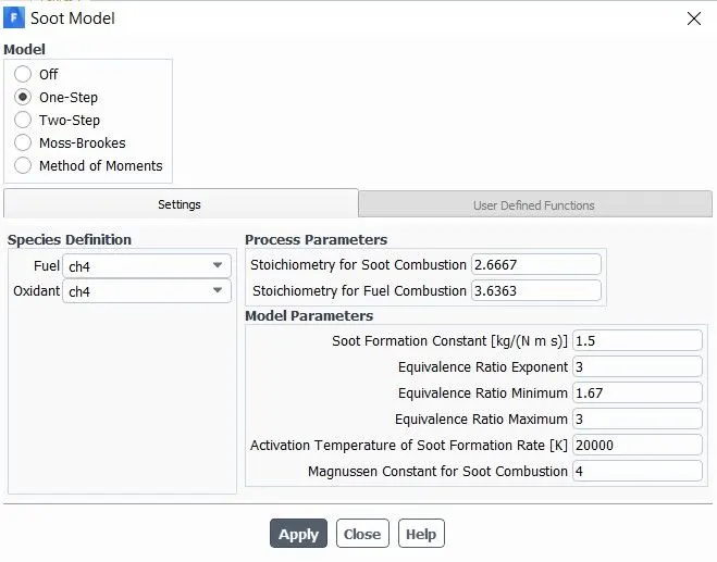
6. Soot Model
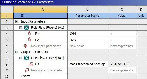
7. Parametric Study Approach
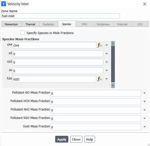
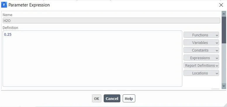
- In the Simulation, 5% to 30% of water(H2O) is added to the fuel(methane CH4).
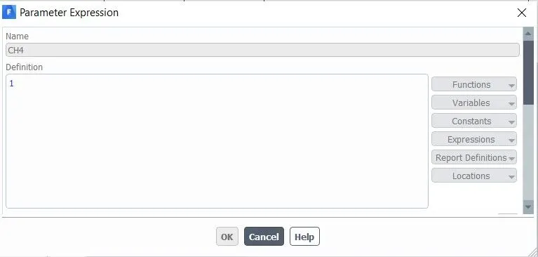
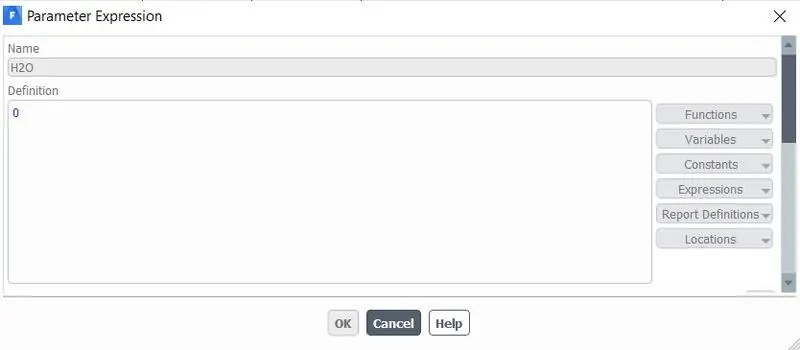
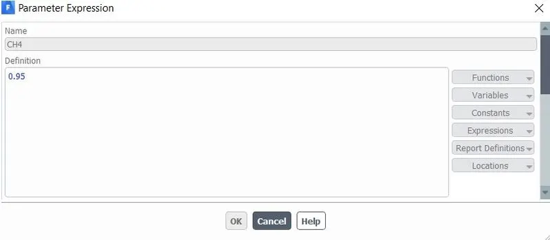
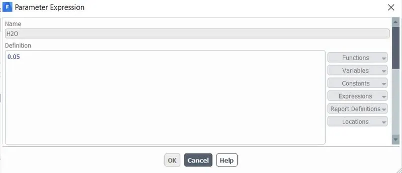
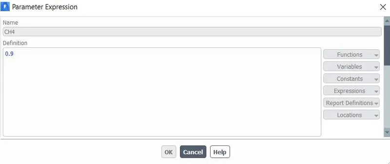
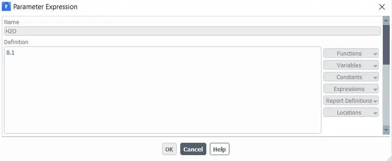
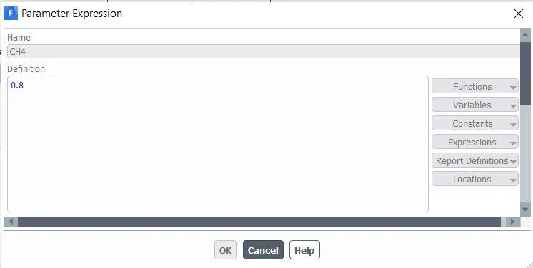
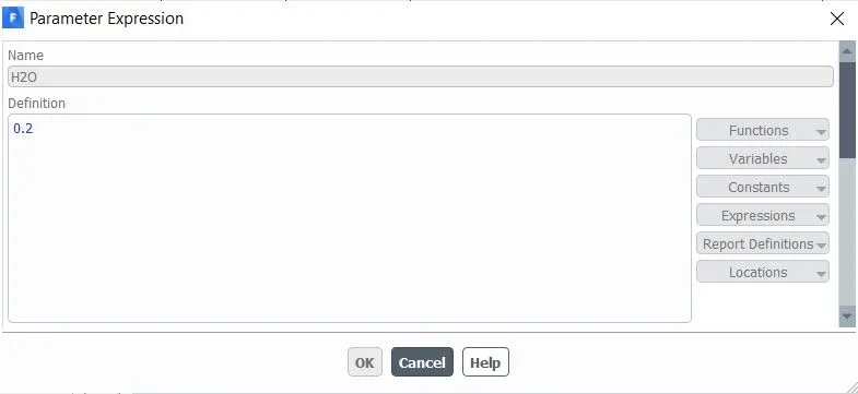
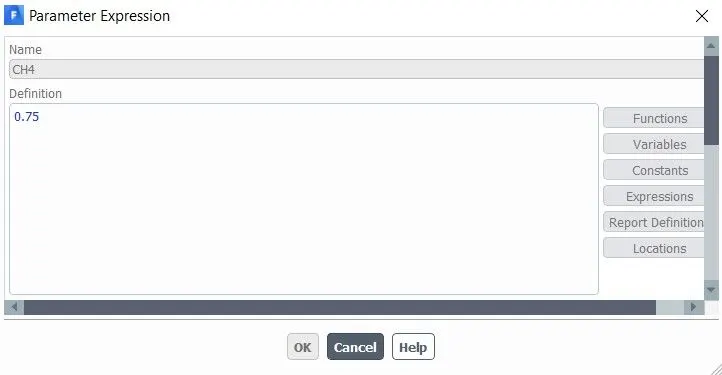
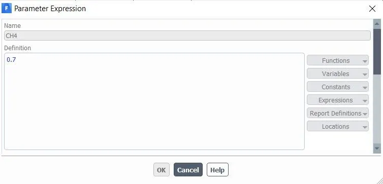
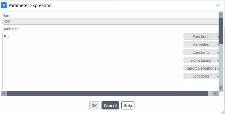
- So the Input Parametric expression is used in the Fuel inlet boundary condition species of methane and water (CH4 and H2O).
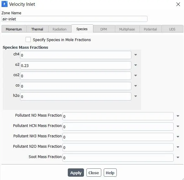
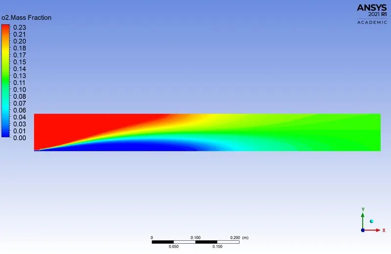
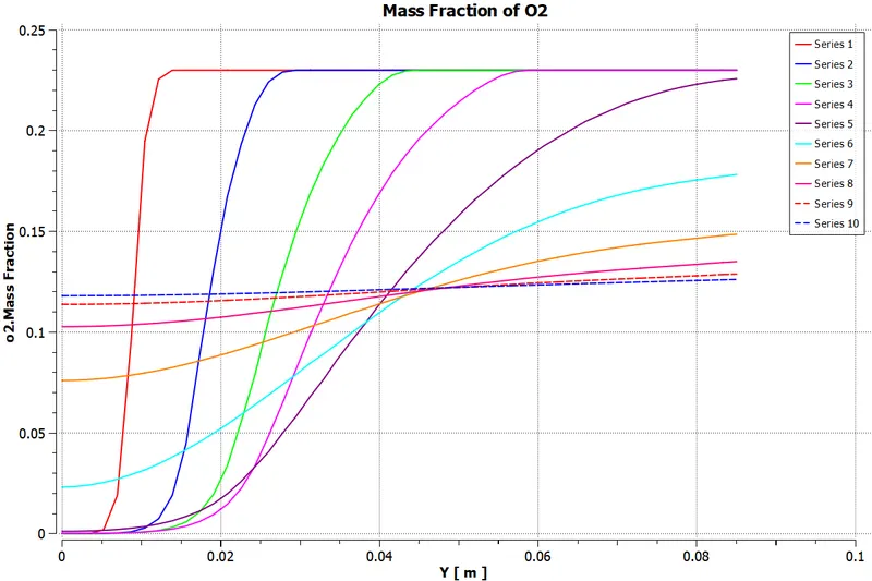
- The Air inlet boundary condition species of oxygen(O2) is constant at 0.23 mass fraction.
- The Mass Fraction of Soot formation is used as output parameters.
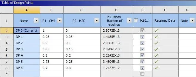
| Part | Design points | Methane(CH4) | Water(H2O) |
| 1 | DP0 | 1 | 0 |
| 2 | DP1 | 0.95 | 0.05 (5%) |
| DP2 | 0.9 | 0.1 (10%) | |
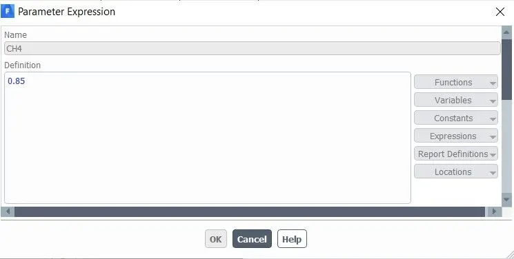
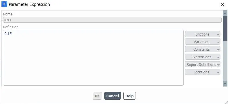
| DP3 | 0.85 | 0.15 (15%) | |
| DP4 | 0.8 | 0.2 (20%) | |
| DP5 | 0.75 | 0.25 (25%) | |
| DP6 | 0.7 | 0.3 (30%) |
8. Boundary conditions
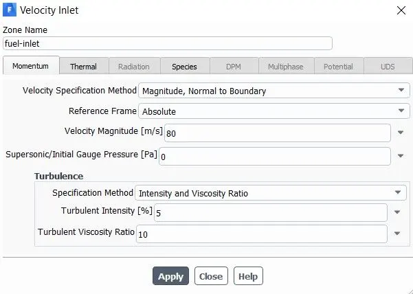
A. Fuel Inlet:-
- Velocity = 80 m/s
- Temperature = 300 K
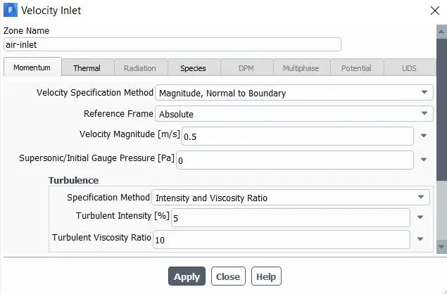
B. Air Inlet:-
- Velocity = 0.5 m/s
- Temperature = 300 K
9. Initialization and Calculation.
- Hybrid Initialization is used.
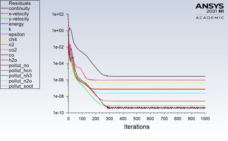
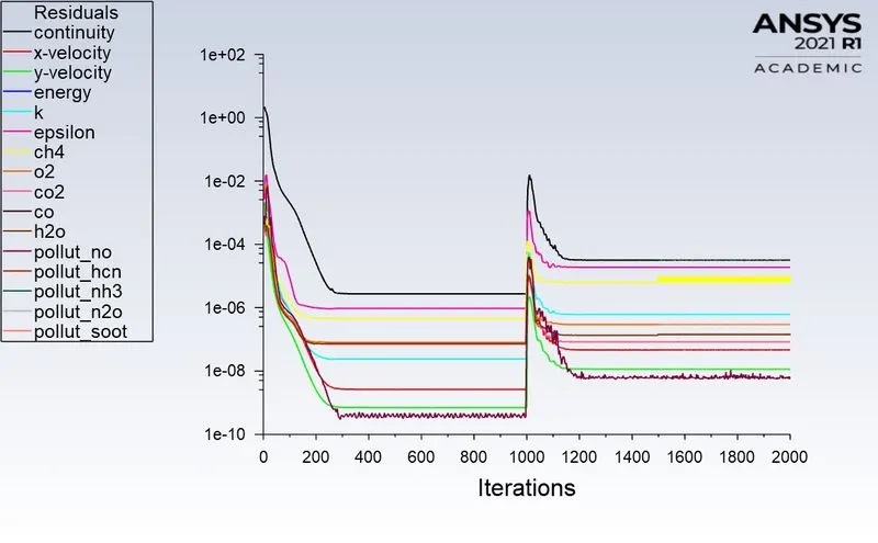
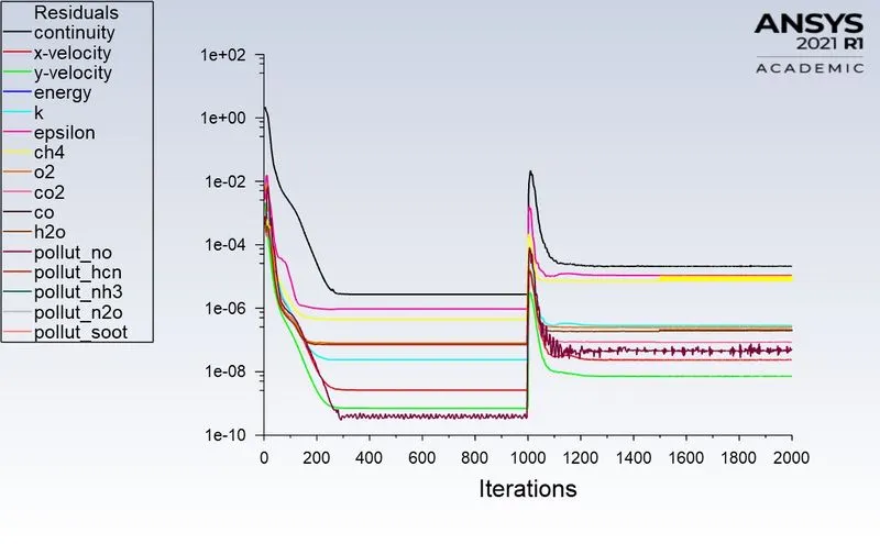
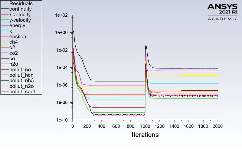
- To run it for 1000 iteration.
Parametric Result:-
Input and Output Parameters:-
Design Points:-
*****************************************************************************************
Result and Output Plots
Part - I:- Without adding water (DP0).
1. Parametric Expression of Species:-
2. Residuals:-
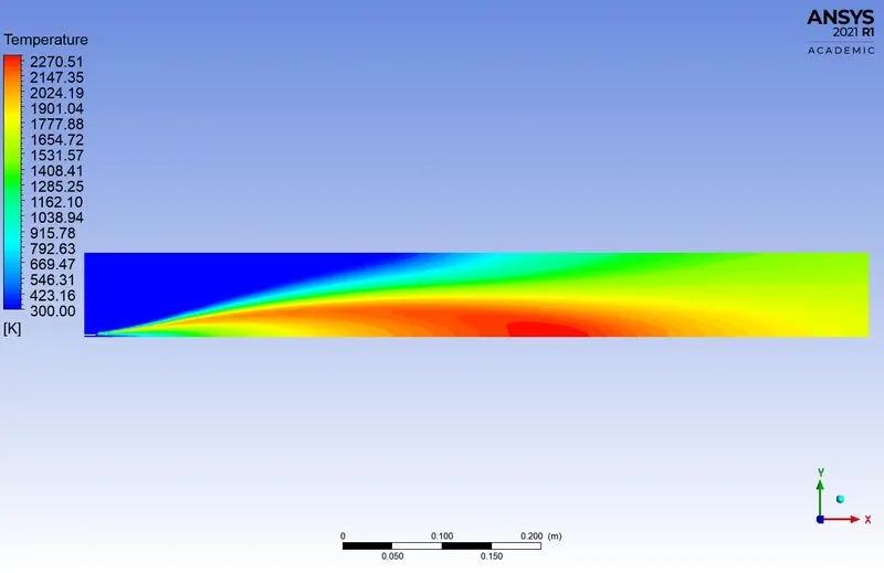
3. Temperature Plot:-
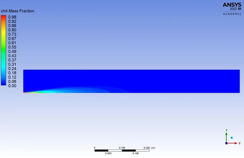
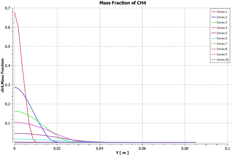
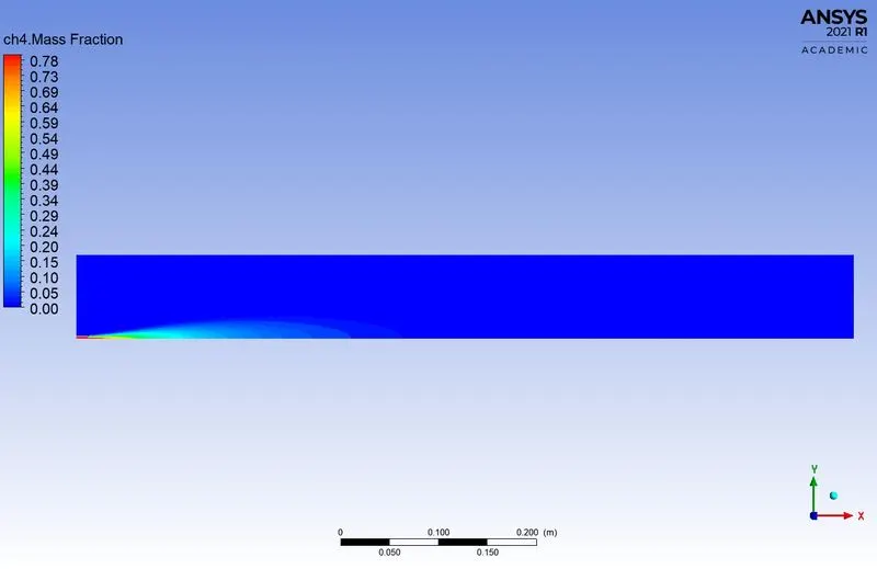
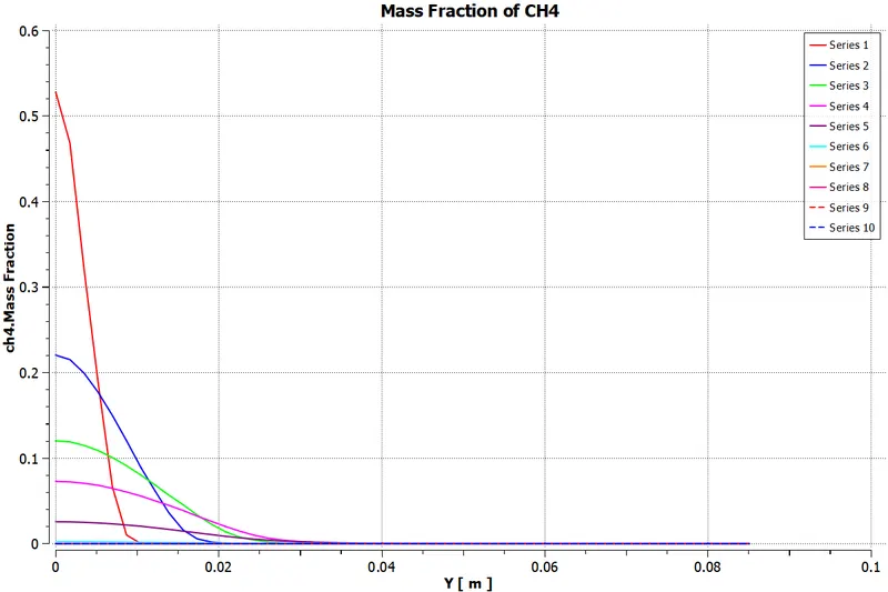
4. Methane (CH4):-
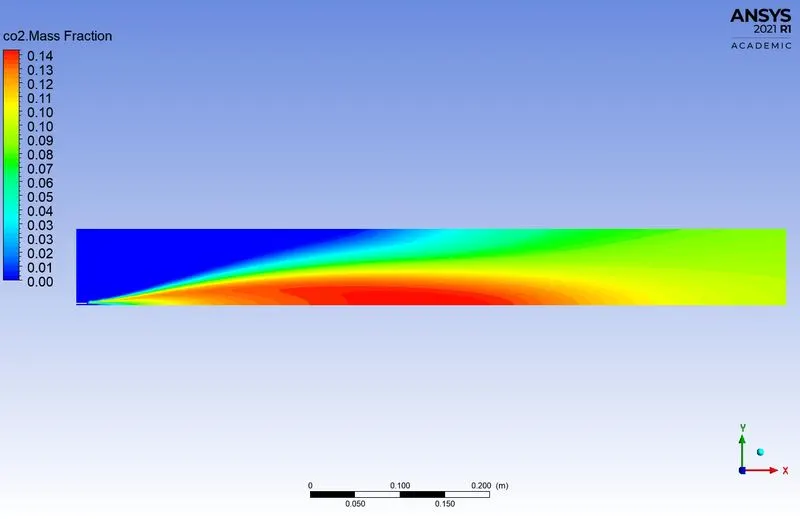
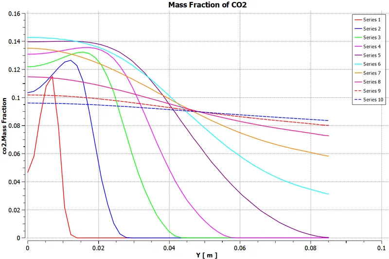
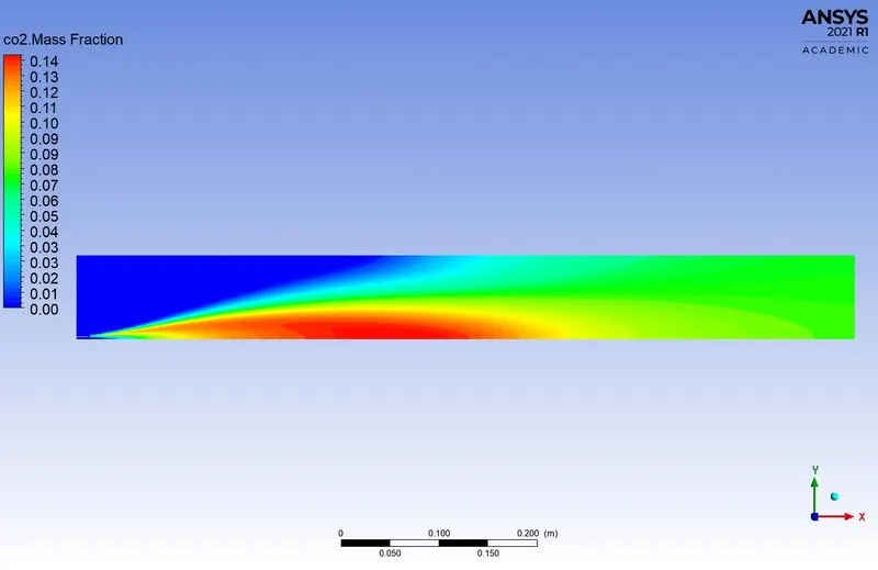
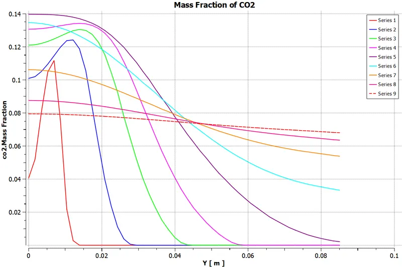
5. Carbon dioxide (CO2):-
6. Water (H2O):-
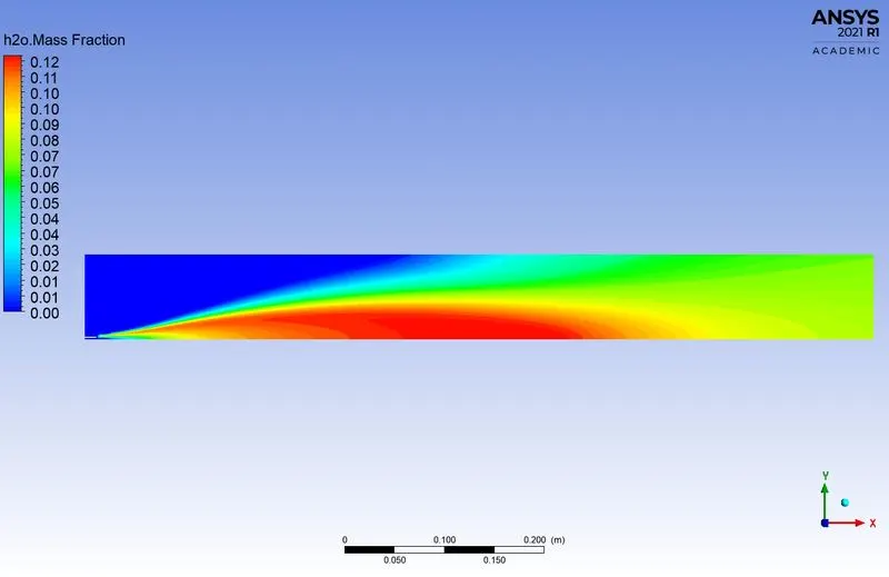
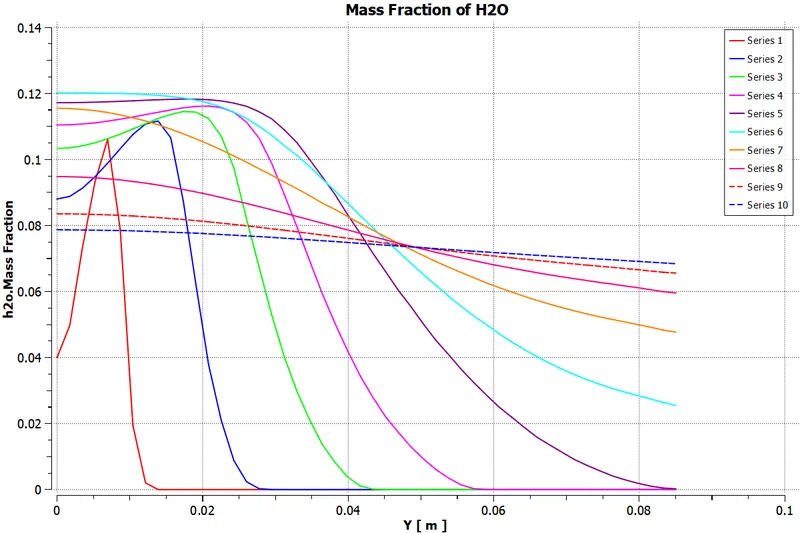
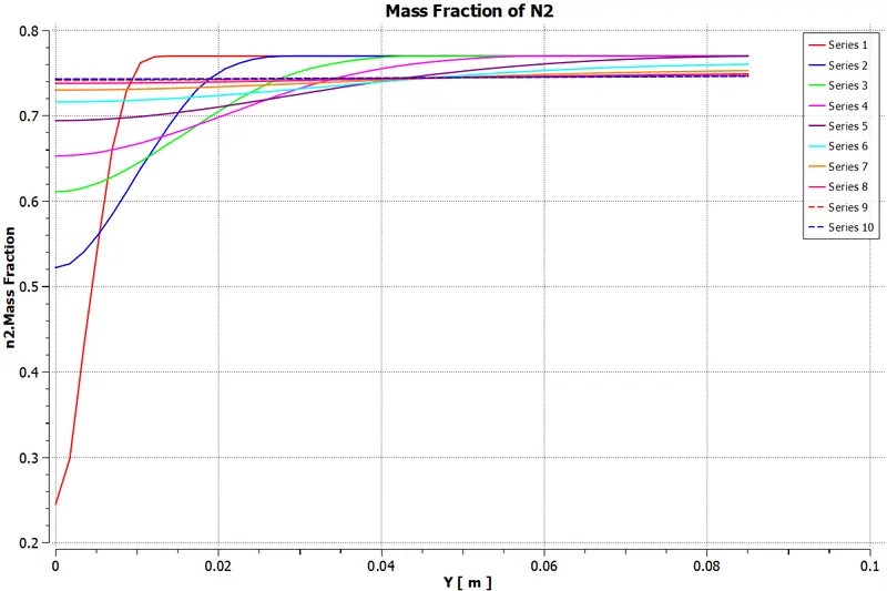
7. Nitrogen (N2):-
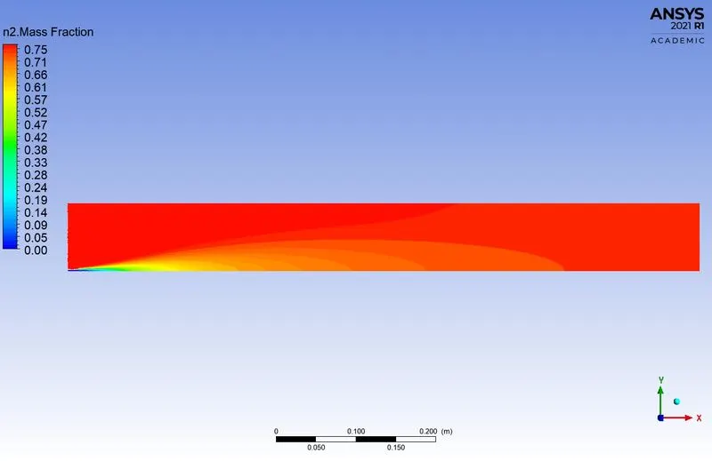
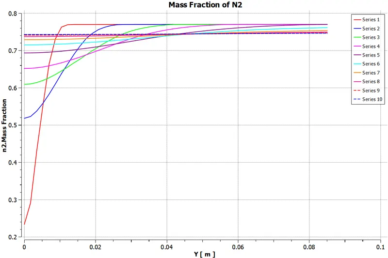
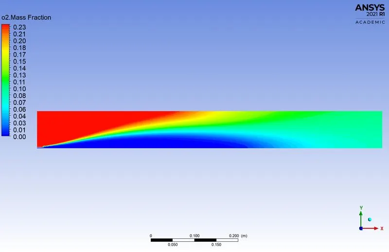
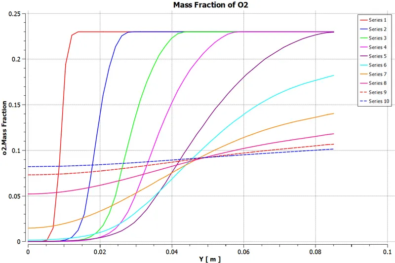
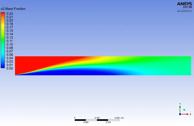
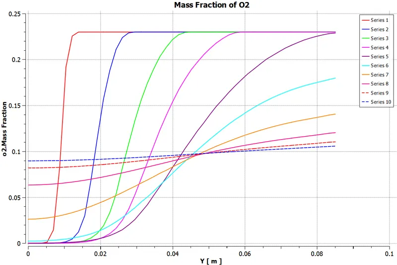
8. Oxygen (O2):-
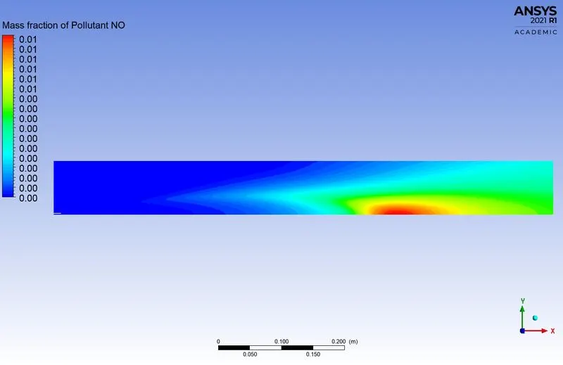
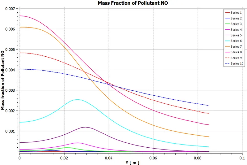
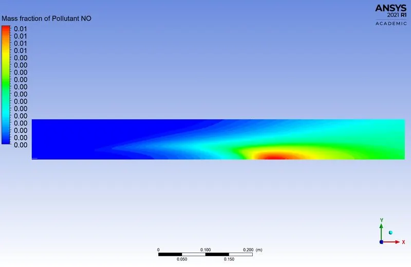
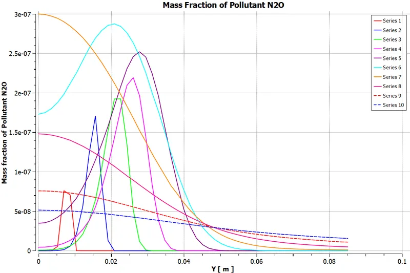
9. NOx Emission:-
Nitric Oxide (NO) and Nitrous Oxide (N2O)
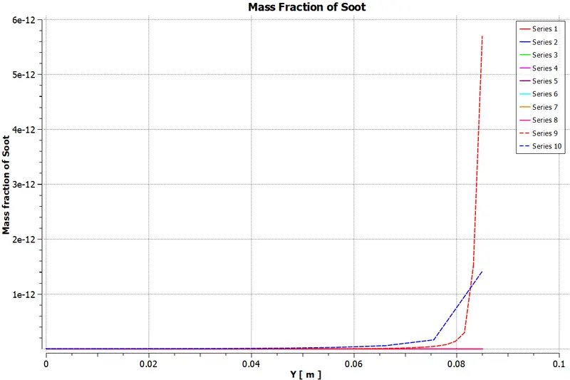
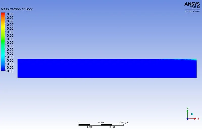
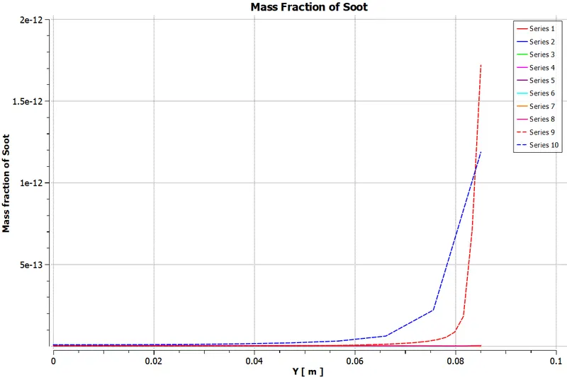
10. Soot Formation:-
*****************************************************************************************
Part - II:- Adding of water into 5% to 30% in fuel.
Case-1 (DP1):-
1. Parametric Expression of Species:-
2. Residuals:-
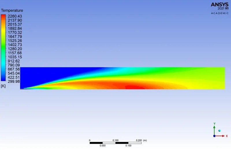
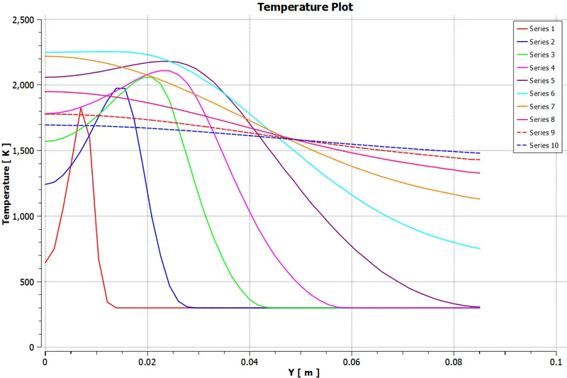
3. Temperature Plot:-
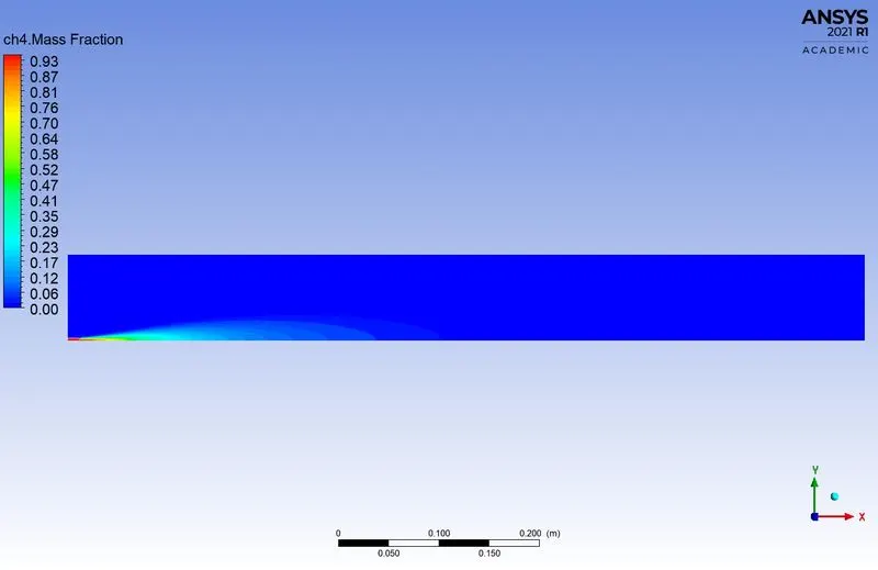
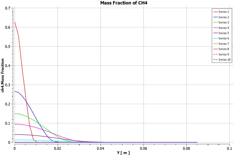
4. Methane (CH4):-
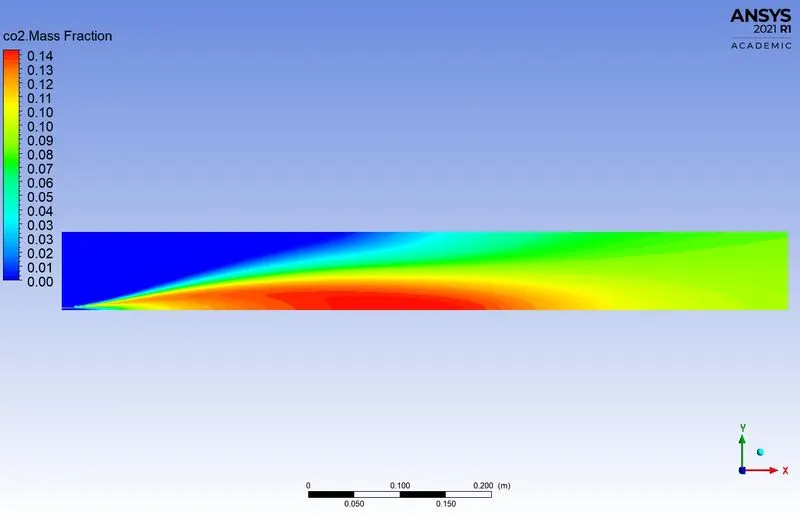
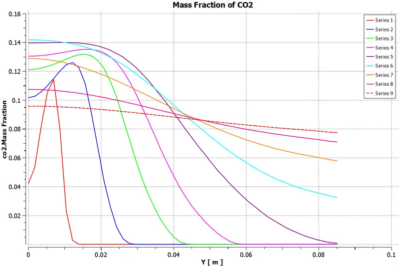
5. Carbon dioxide (CO2):-
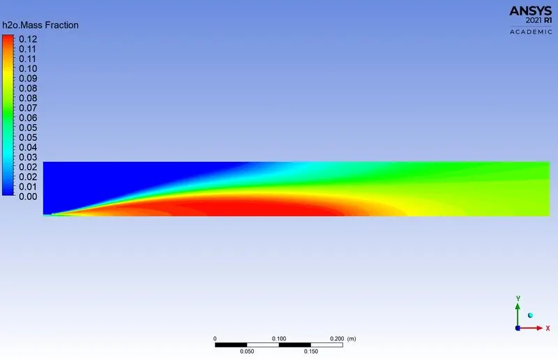
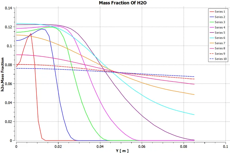
6. Water (H2O):-
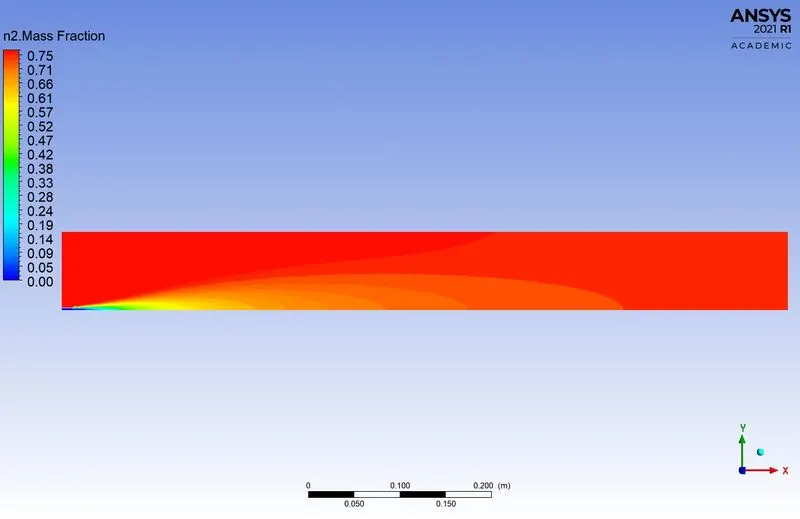
7. Nitrogen (N2):-
8. Oxygen (O2):-
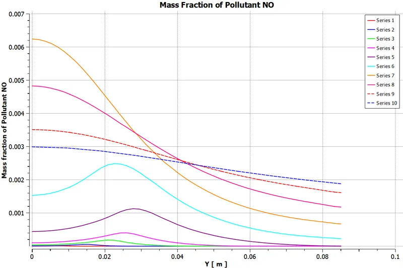
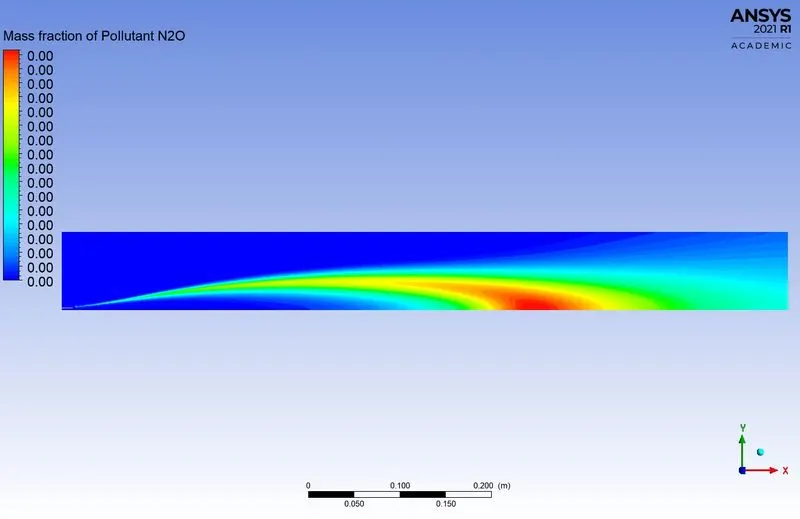
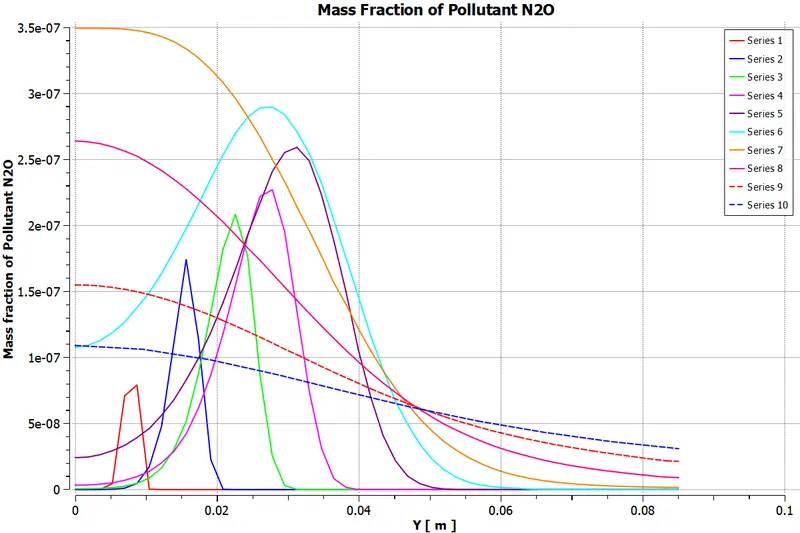
9. NOx Emission:-
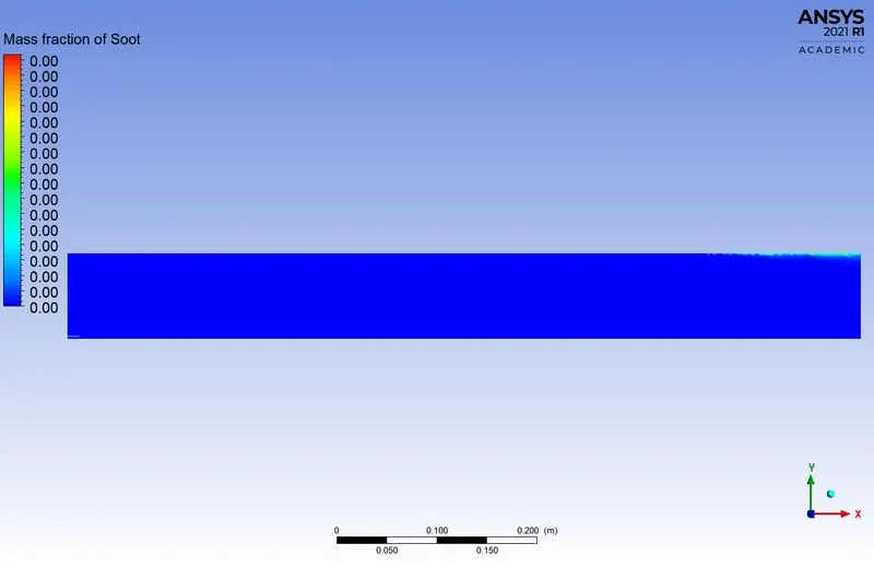
10. Soot Formation:-
*****************************************************************************************
Case-2 (DP2):-
1. Parametric Expression of Species:-
2. Residuals:-
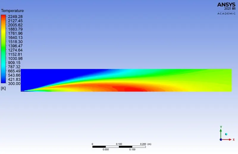
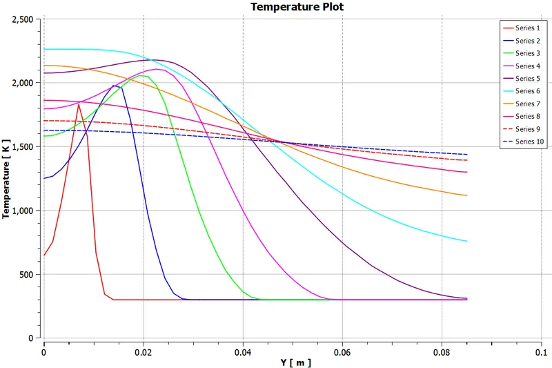
3. Temperature Plot:-
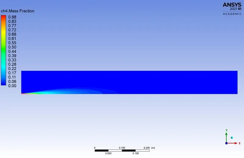
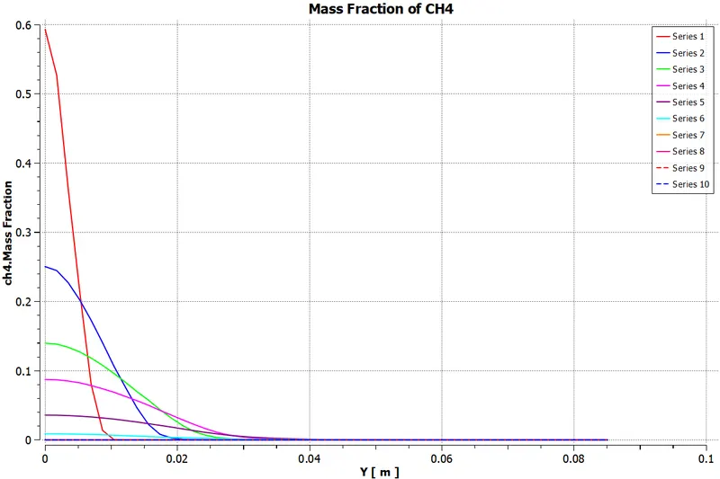
4. Methane (CH4):-
5. Carbon dioxide (CO2):-
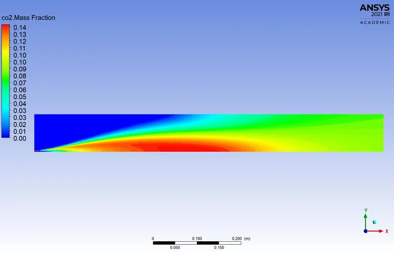
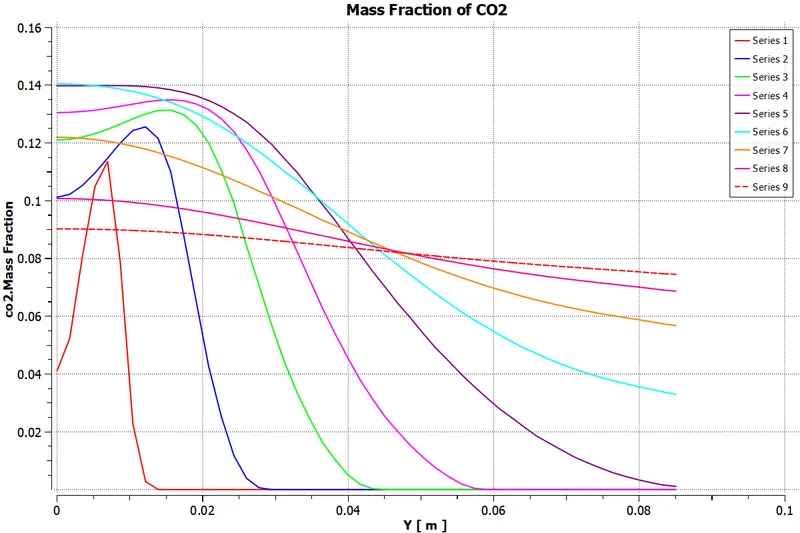
6. Water (H2O):-
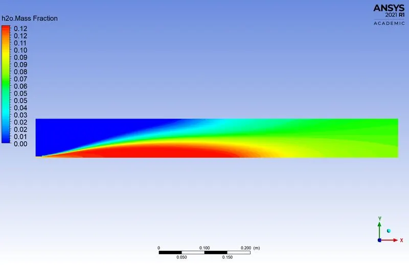
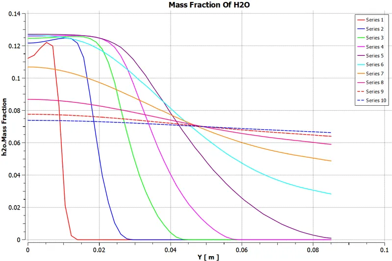
7. Nitrogen (N2):-
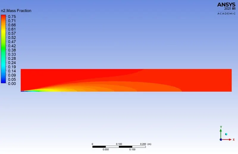
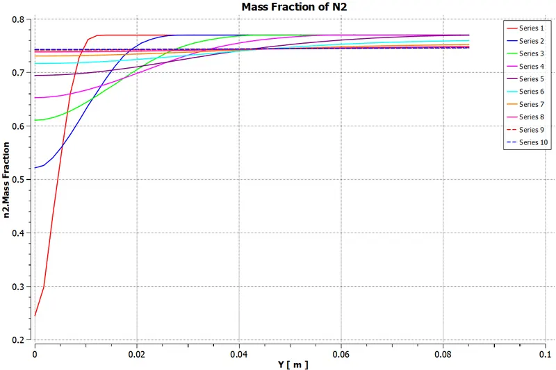
8. Oxygen (O2):-
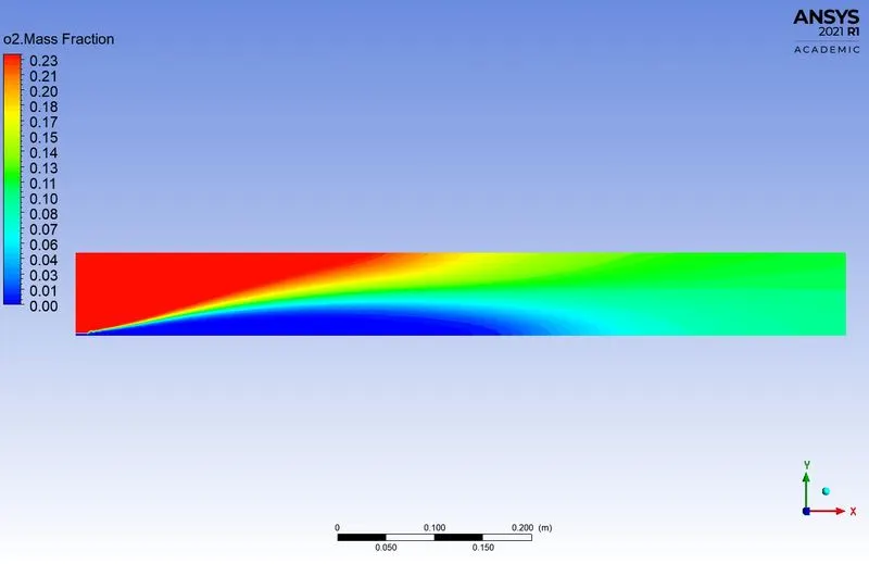
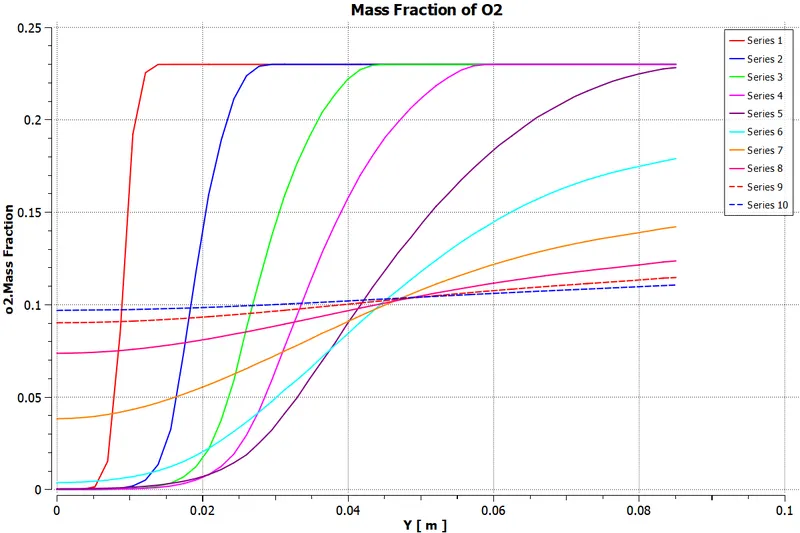
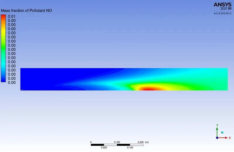
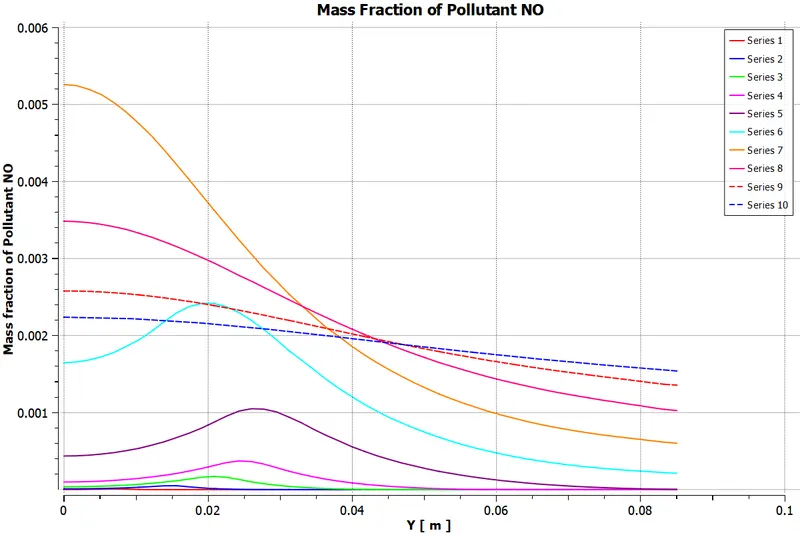
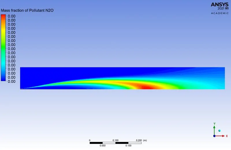
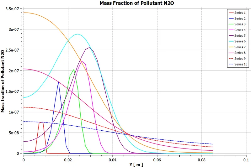
9. NOx Emission:-
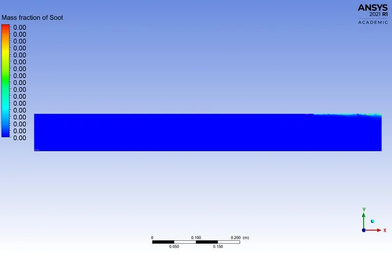
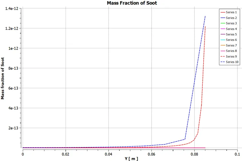
10. Soot Formation:-
*****************************************************************************************
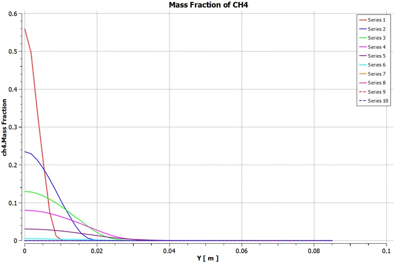
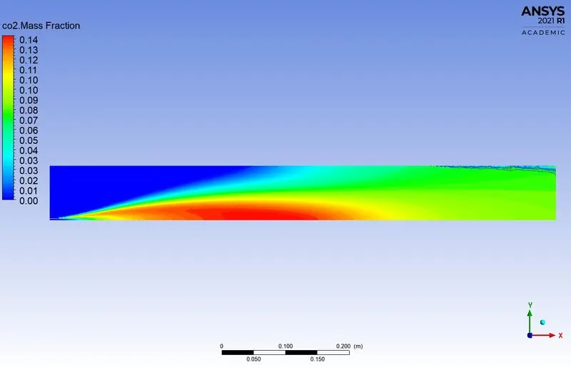
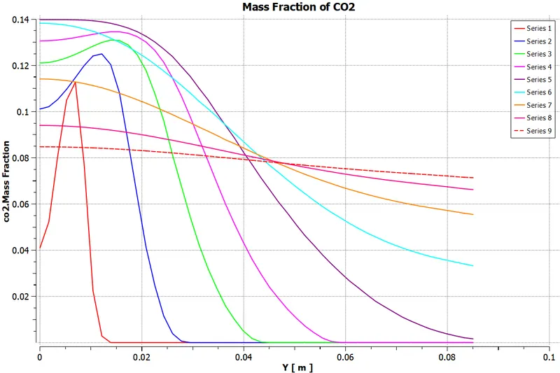
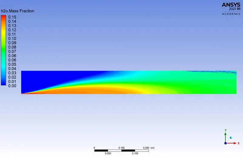
Case-3 (DP3):-
1. Parametric Expression of Species:-
2. Residuals:-
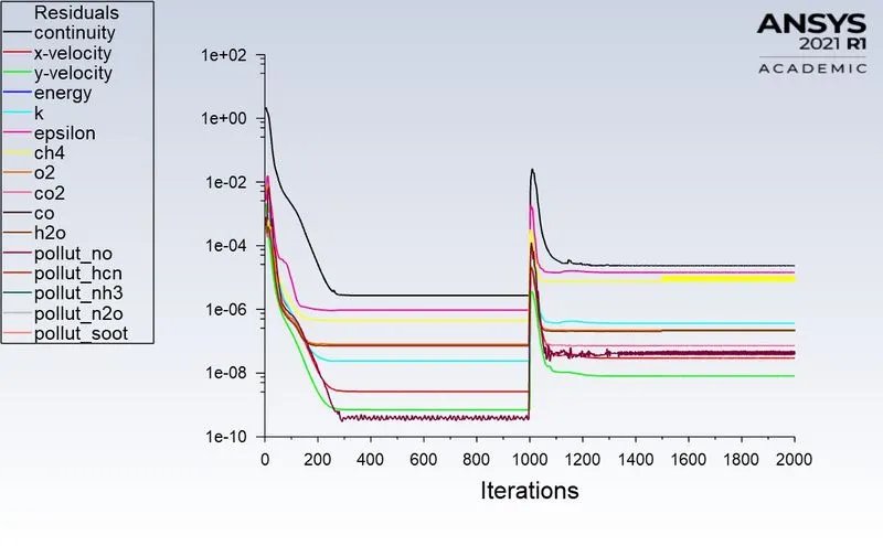
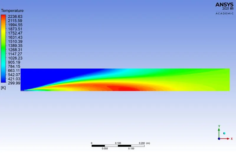
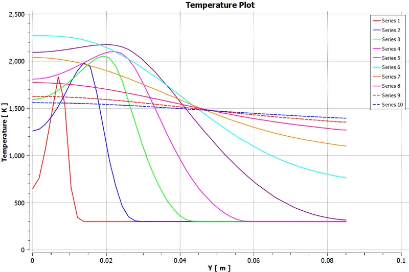
3. Temperature Plot:-
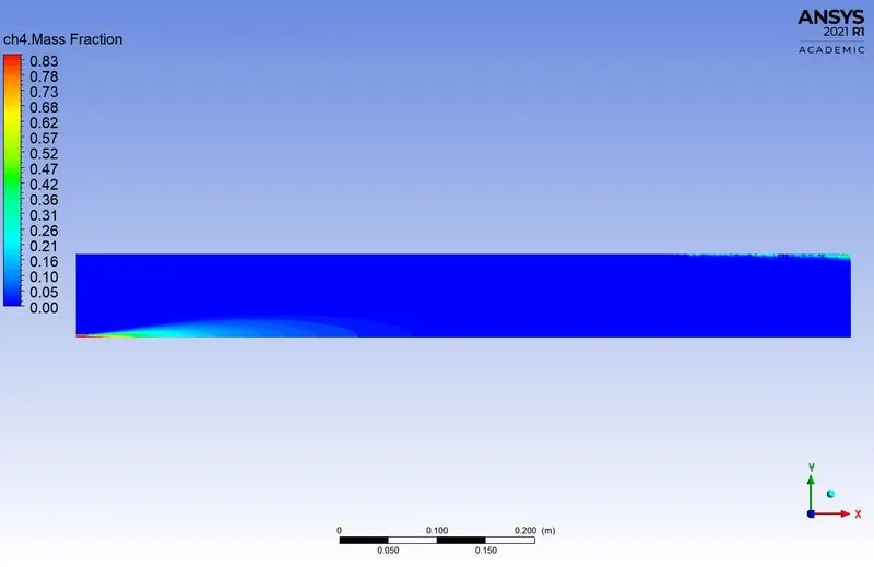
4. Methane (CH4):-
5. Carbon dioxide (CO2):-
6. Water (H2O):-
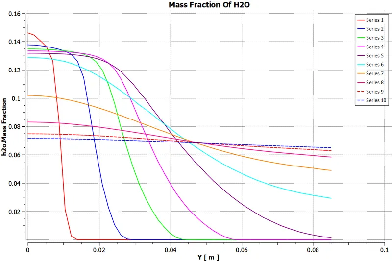
7. Nitrogen (N2):-
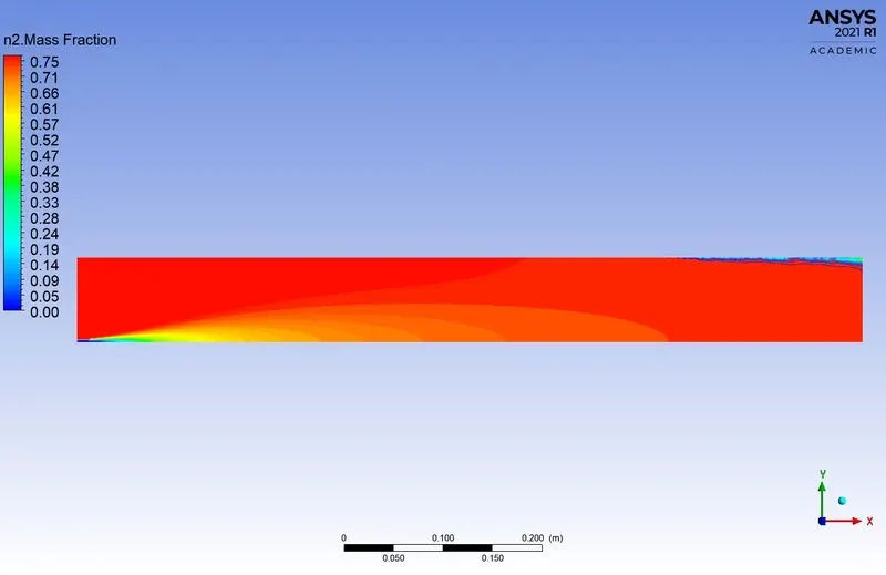
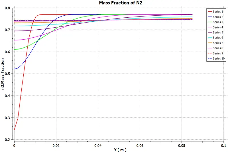
8. Oxygen (O2):-
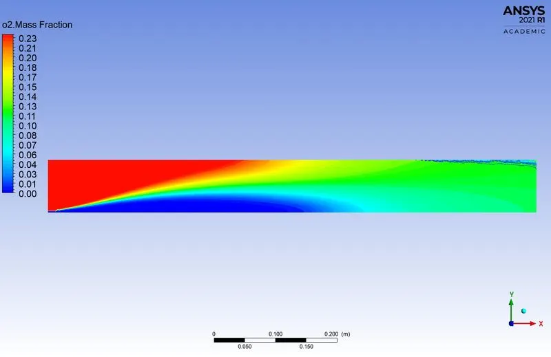
9. NOx Emission:-
10. Soot Formation:-
*****************************************************************************************
Case-4 (DP4):-
1. Parametric Expression of Species:-
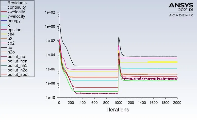
2. Residuals:-
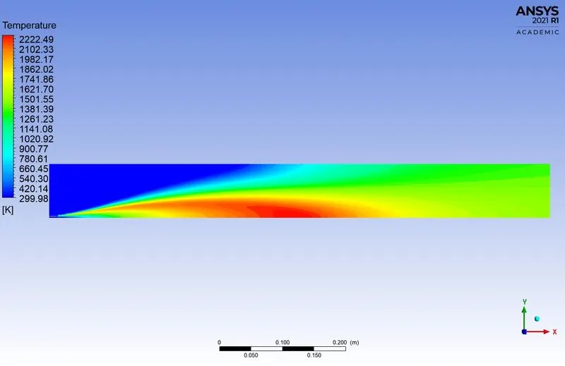
3. Temperature Plot:-
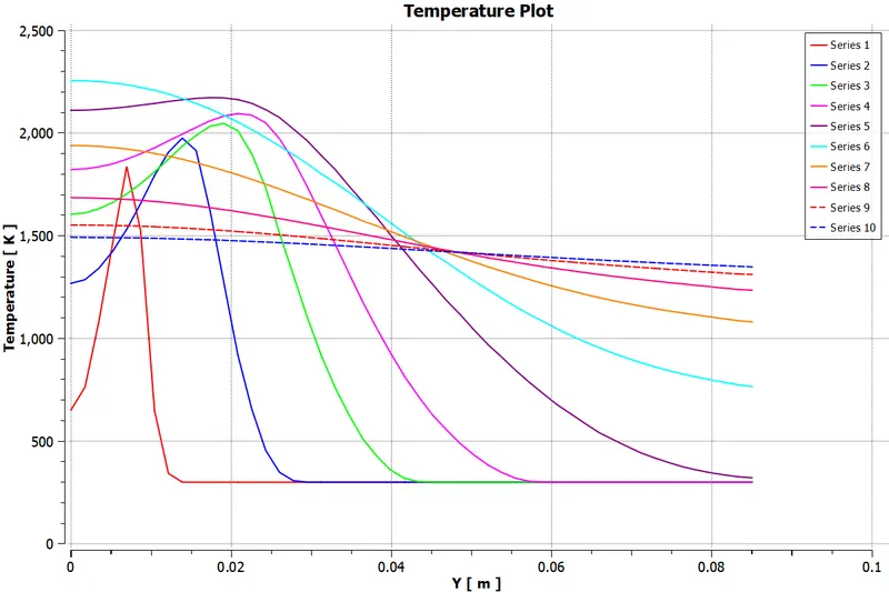
4. Methane (CH4):-
5. Carbon dioxide (CO2):-
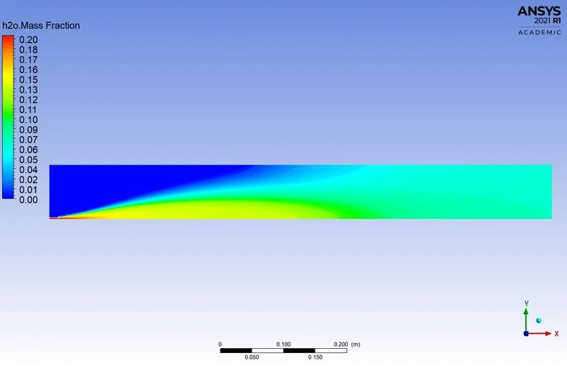
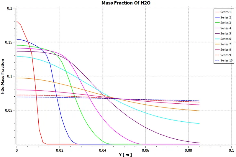
6. Water (H2O):-
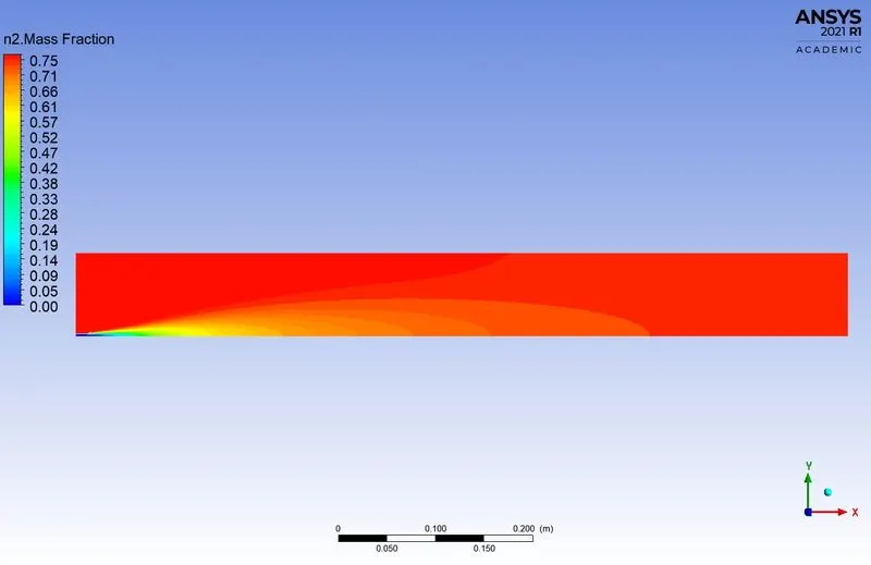
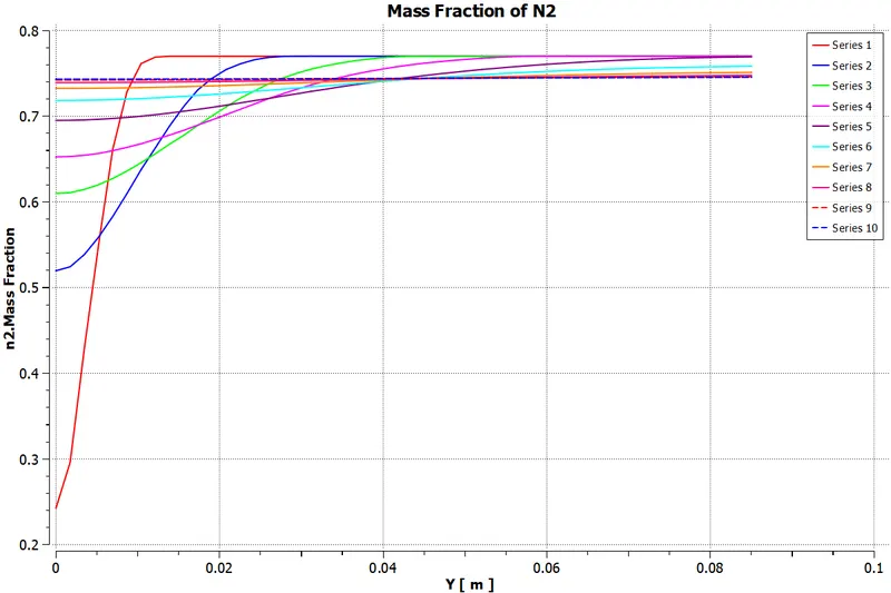
7. Nitrogen (N2):-
8. Oxygen (O2):-
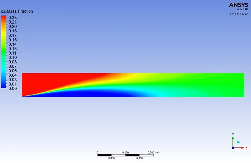
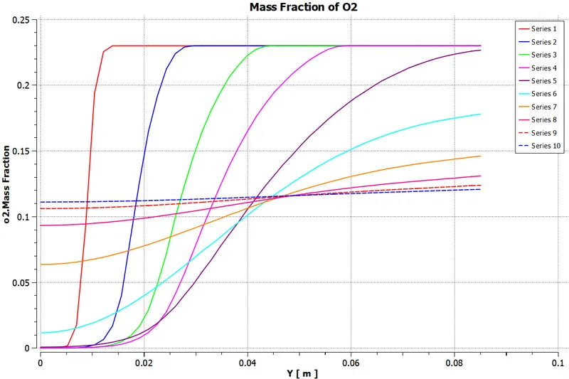
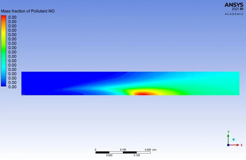
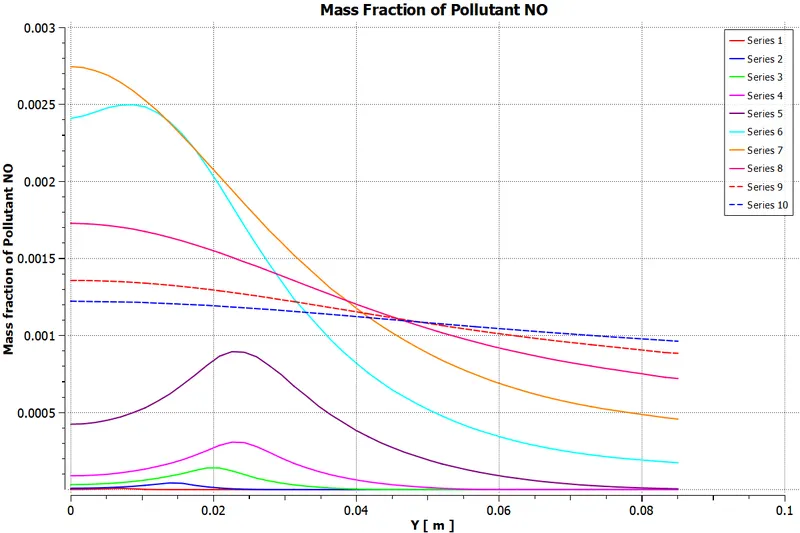
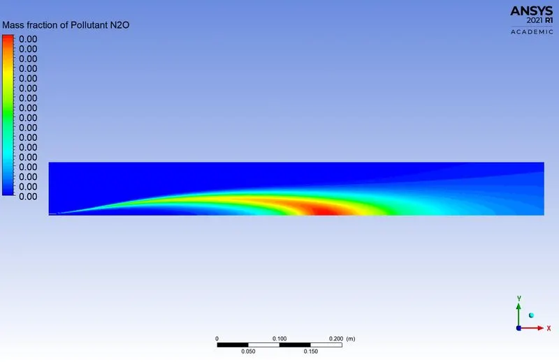
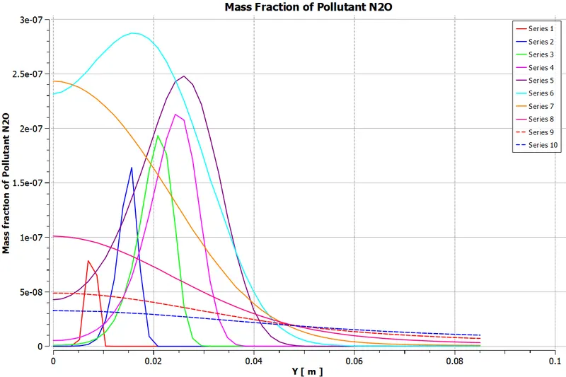
9. NOx Emission:-
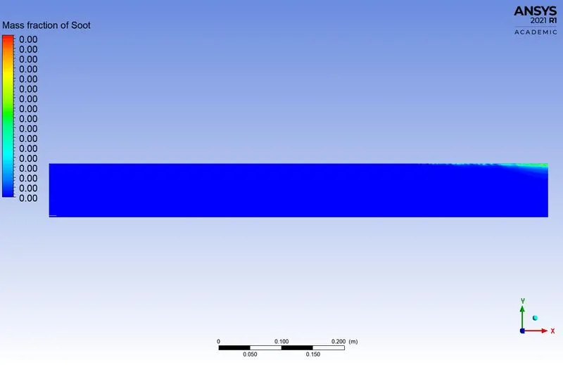
10. Soot Formation:-

*****************************************************************************************
Case-5 (DP5):-
1. Parametric Expression of Species:-
2. Residuals:-
3. Temperature Plot:-
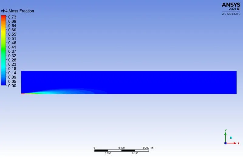
4. Methane (CH4):-
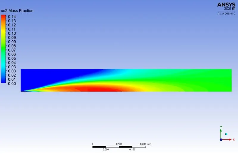
5. Carbon dioxide (CO2):-
6. Water (H2O):-
7. Nitrogen (N2):-
8. Oxygen (O2):-
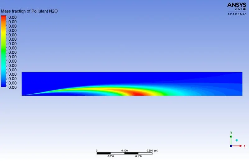
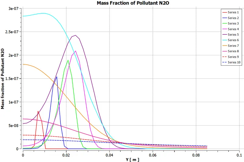
9. NOx Emission:-
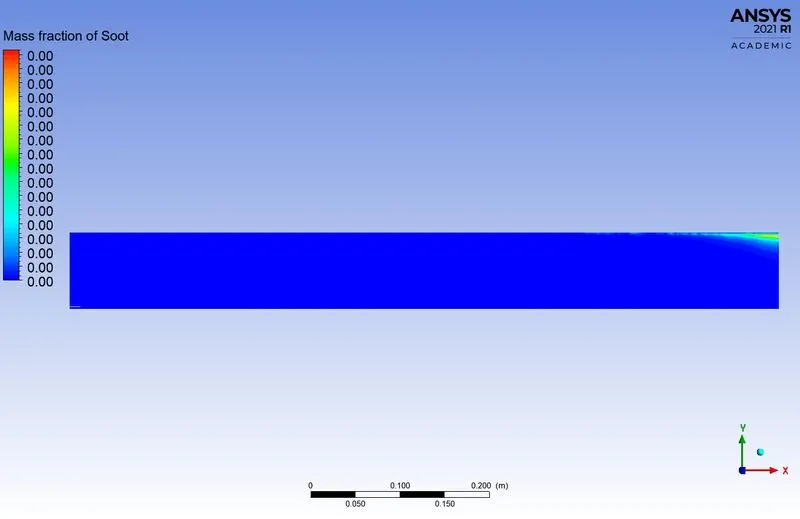
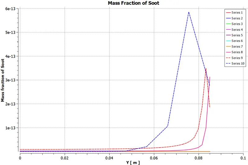
10. Soot Formation:-
*****************************************************************************************
Case-6 (DP6):-
1. Parametric Expression of Species:-
2. Residuals:-
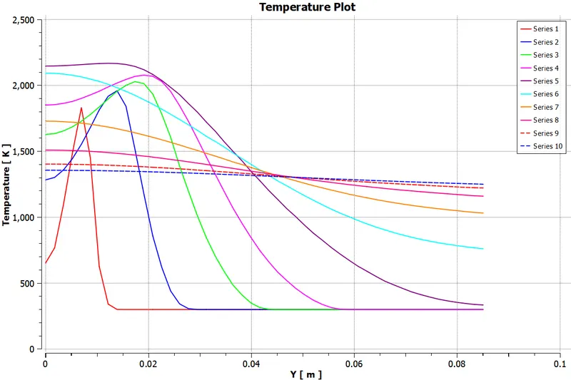
3. Temperature Plot:-
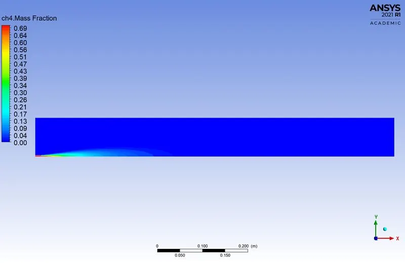
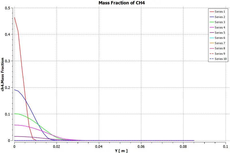
4. Methane (CH4):-
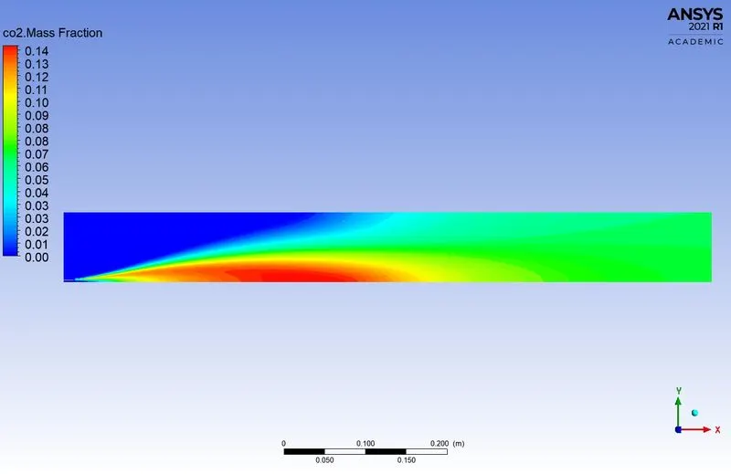
5. Carbon dioxide (CO2):-
6. Water (H2O):-
7. Nitrogen (N2):-
8. Oxygen (O2):-
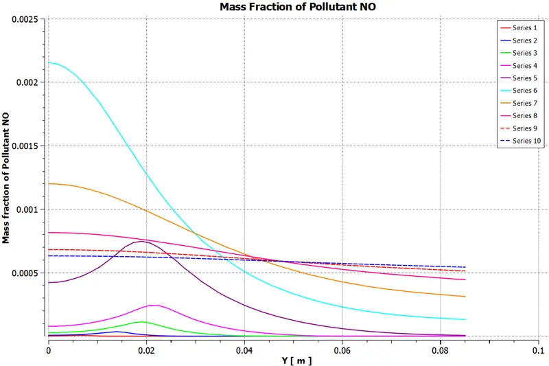
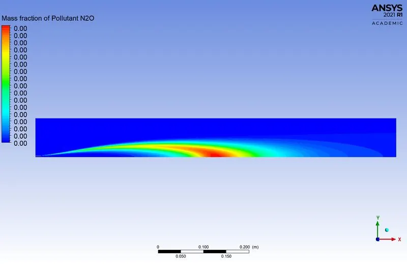
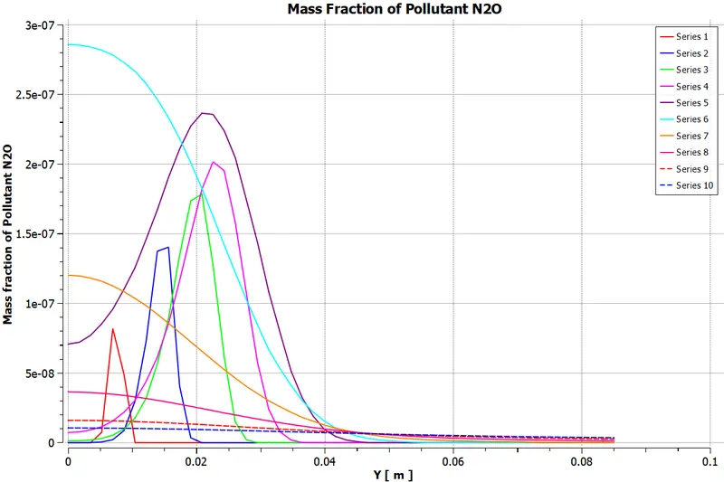
9. NOx Emission:-
10. Soot Formation:-
*****************************************************************************************
Conclusion:-
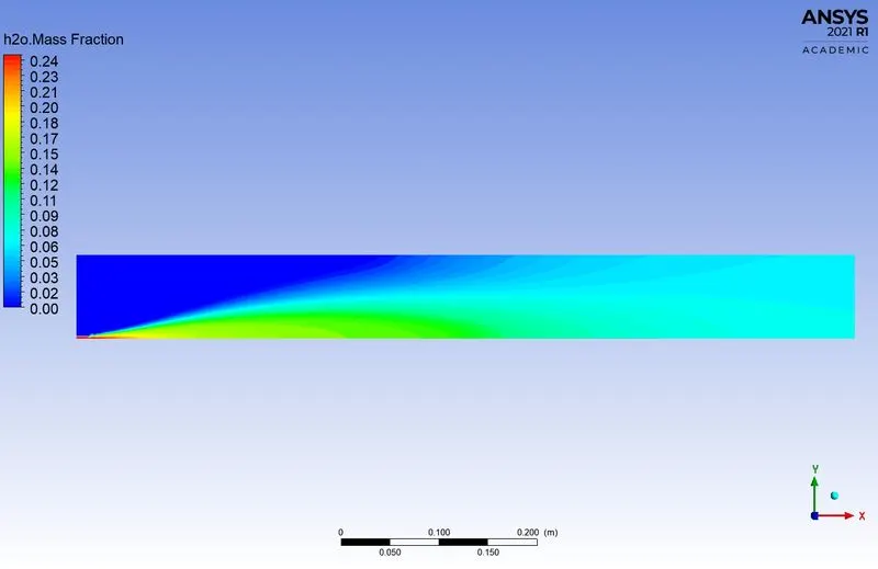
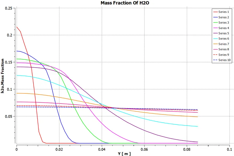
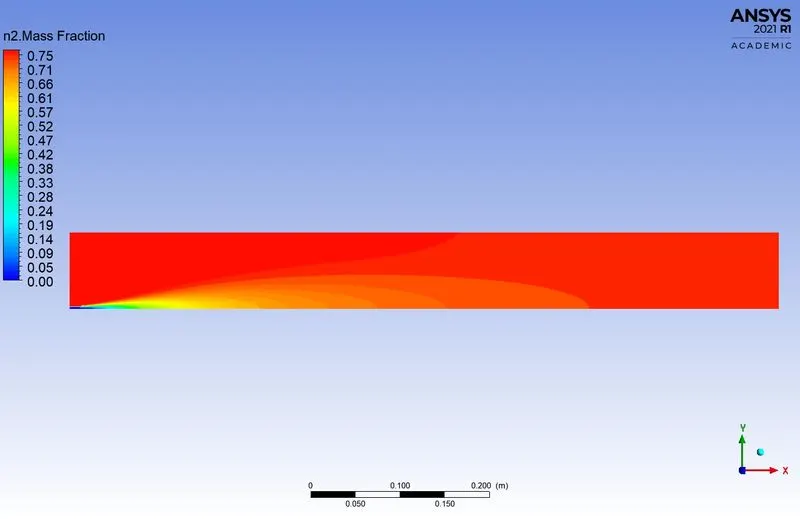
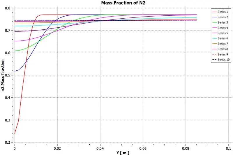
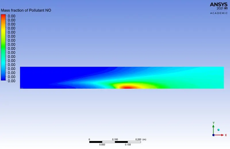
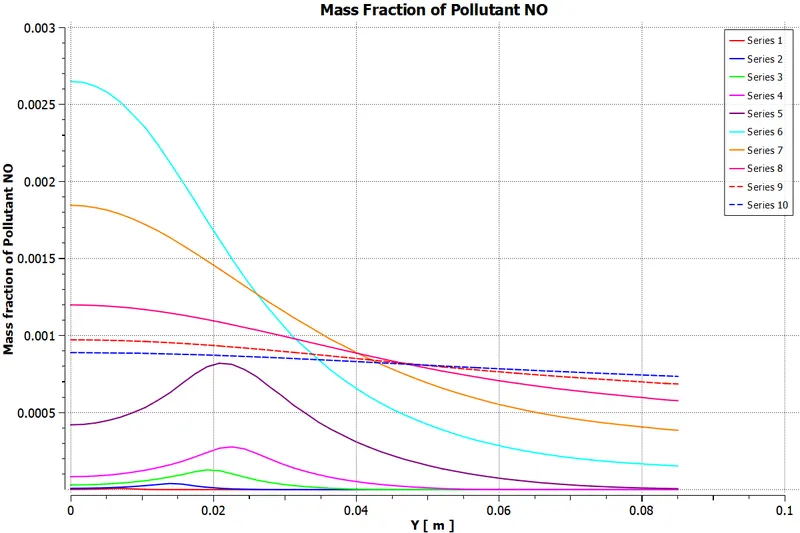
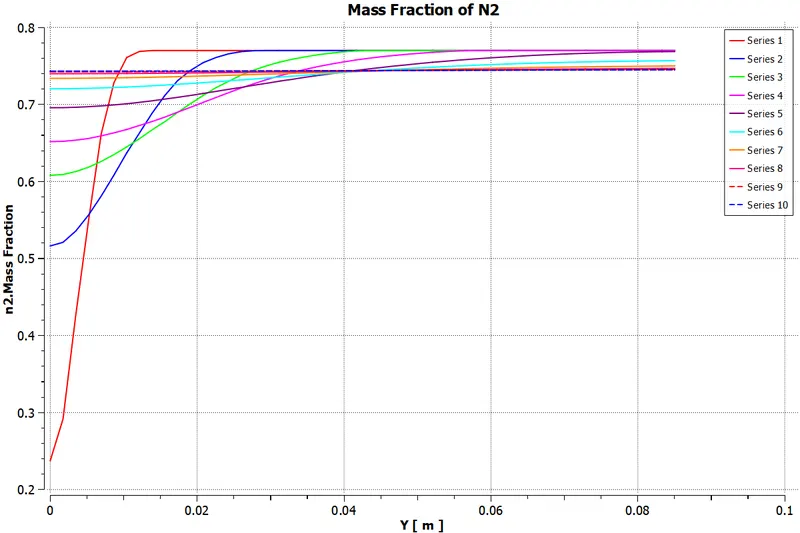
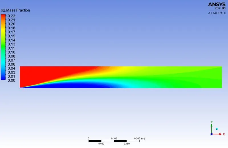
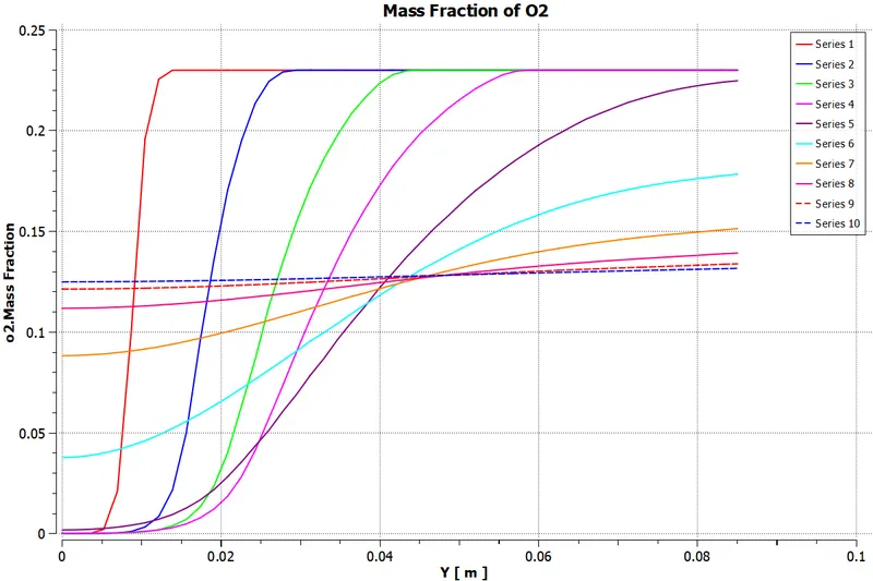
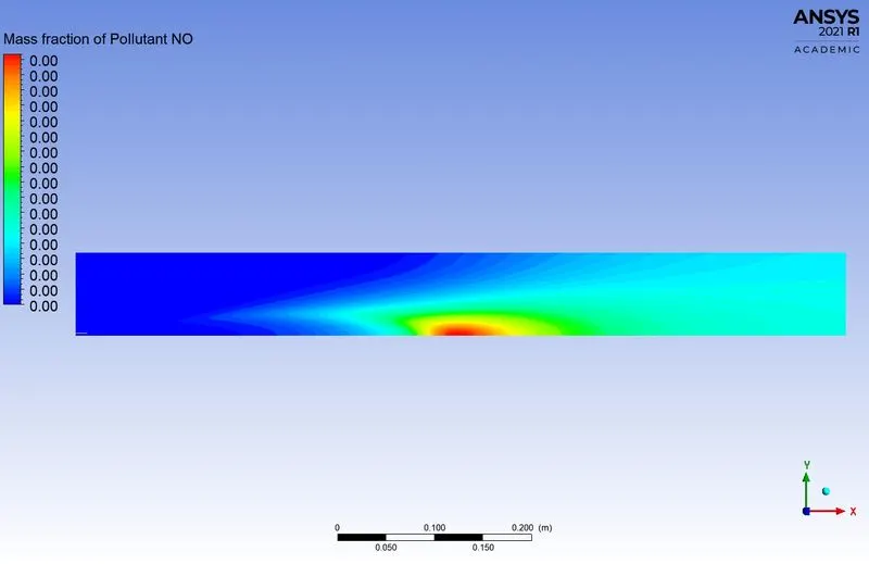
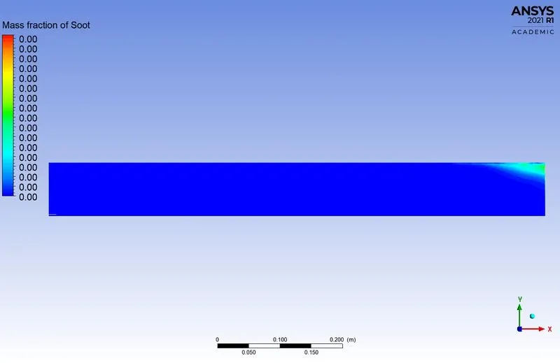
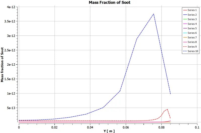
- From the above plots and graph, the NOx emission and Soot formation at the outlet is reduced by adding water to the fuel.
- The addition of water in the fuel reduces the toxic gas from the combustor. But the efficiency of the combustor is decreased.
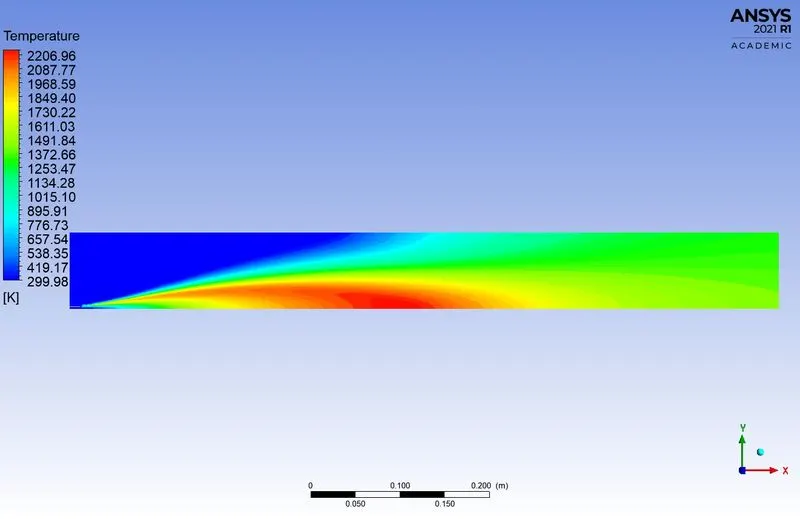
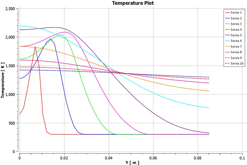
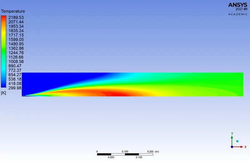
- The water dilutes the calories generated by the combustion and results in a decrease in combustion temperature. If the temperature is reduced the NOx cannot be formed in great concentration.
- In the simulation, the eddy dissipation model is used as a combustion source for the combustor.
- So, that we can conclude the adding of water in the fuel to decrease the nitrogen oxide and soot formation.