Week 4.2: Project Transient simulation of flow over a throttle body
TRANSIENT SIMULATION OF FLOW OVER A THROTTLE BODY
Aim:-
To simulate the transient state simulation of flow over a throttle body.
Objective:-
- Perform a transient state simulation of flow over a throttle body.
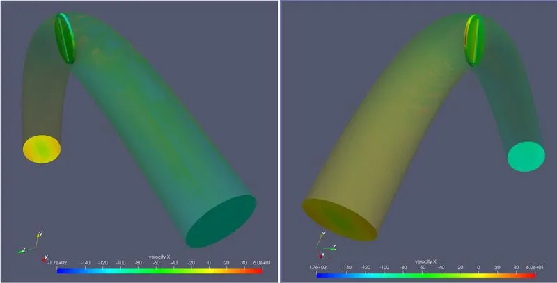
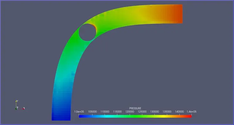
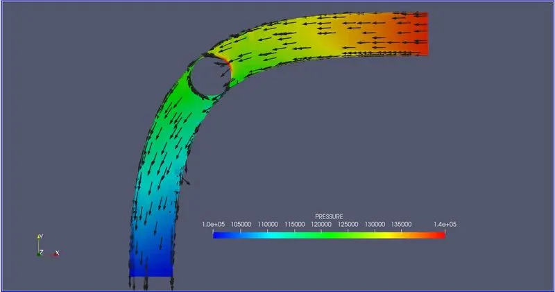
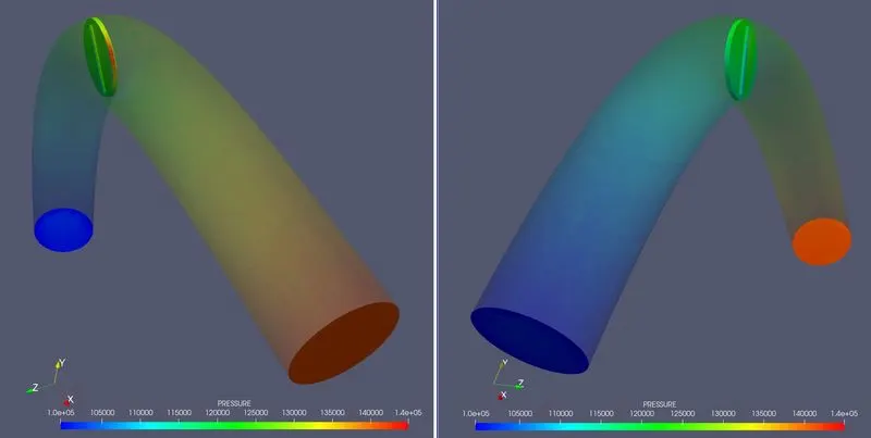
- Post-process the result and show pressure and velocity contours
- Show the mesh with surface edges.
- show the plots for pressure, velocity, mass flow rate and total cell count.
- Also, show the calculation of how you calculated an end time for the simulation.
Introduction:-
Transient State:-
A system is said to be transient or in a transient state when a process variable or variables have been changed and the system has not yet reached a steady state. The time is taken for the circuit to change from one steady-state to another steady state is called the transient time.
Throttle Body:-
The largest piece inside the throttle body is the throttle plate, which is a butterfly valve that regulates the airflow.
In this transient simulation, the valve should be rotated about its normal axis with a specified angle and time. This simulation helps to figure out what is the velocity, pressure mass flow rate at the outlet and the changes in cell count when the throttle valve is rotated.
Throttle Position:-
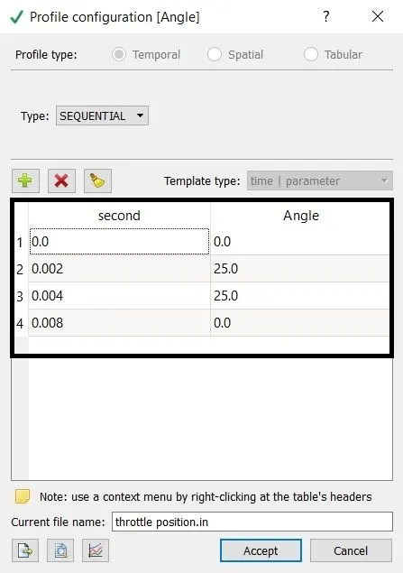
- From 0 to 0.002 s the valve should rotate by 25 degrees.
- From 0.002 to 0.004 s the valve should stay at 25 degrees.
- After which by 0.008 s the valve should get back to its original position.
| Time (s) | Angle (degree) |
| 0 | 0 |
| 0.002 | 25 |
| 0.004 | 25 |
| 0.008 | 0 |
Calculation:-
Length of the Elbow:-
- Create a boundary fence along the centre of the elbow.
- To measure the length change the selection mode to "By boundary fence" (Measure > Distance > Edge > select the boundary fence and apply).
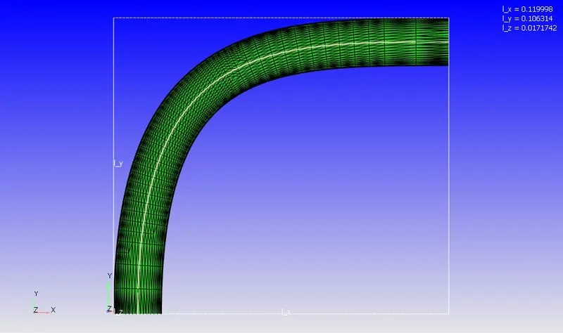
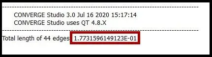
Length of the elbow = 0.1773 m
End Time calculation:-
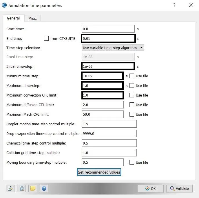
- The characteristic length of the elbow is 0.177 m
- The average velocity of the inlet in the previous simulation of steady-state is 106 m/s.
`"Time taken from inlet to outlet" = 0.177/106`
`"Time taken from inlet to outlet" = 0.00167`
The throttle plate is moving from 0 to 0.008 s. So the end time should be greater than the throttle plate moving time.
`"End time" = 6 xx "Time taken from inlet to outlet"`
`"End Time" = 6 xx 0.00167`
`therefore "End Time" = 0.01 sec`
SIMULATION PROCESS
A. Geometry Setup:-
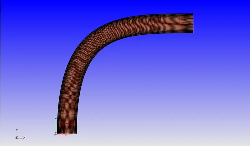
- Import the elbow.stl file in converge CFD.
- And scale the geometry from millimeter to meter.
- Creating the boundary face and delete the thickness of the elbow.
- After deleting the thickness the open edge is created. to the open edge is closed by patch command.
Geometry:-
Boundary Flagging:-
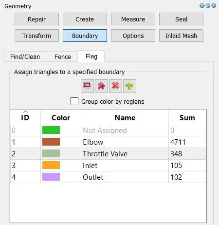
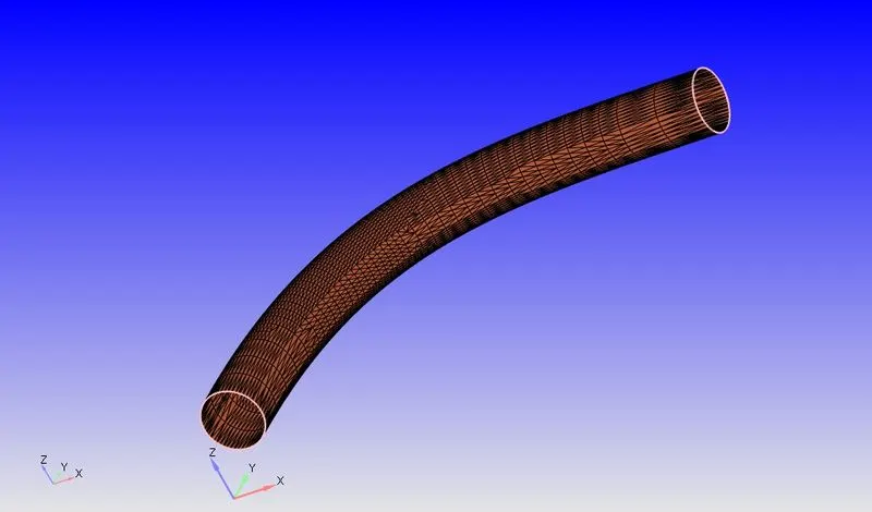
Fig(a). Elbow
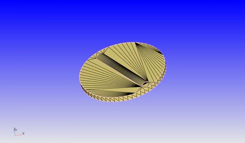
Fig(b). Throttle Valve
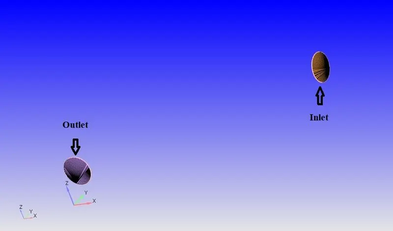
Fig(a). Inlet and Outlet
B. Case Setup:-
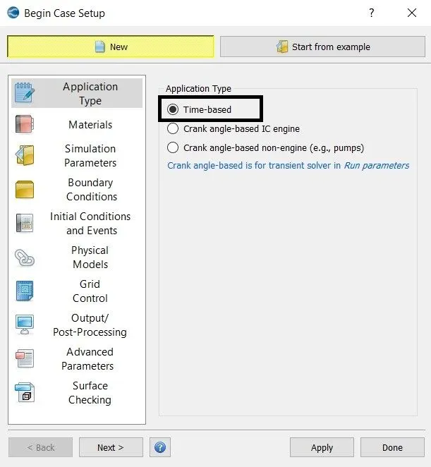
1. Application Type:-
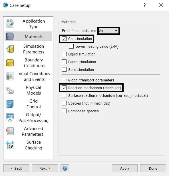
2. Material:-
3. Simulation Parameters:-
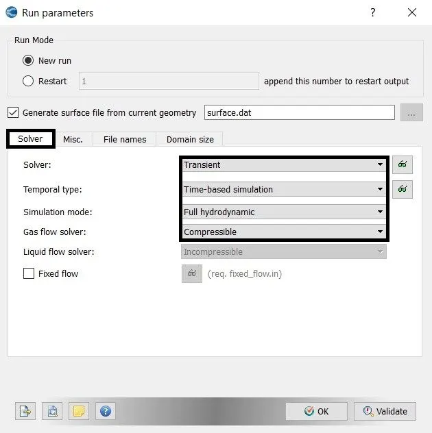
- A transient solver is used.
- The steady-state monitor is enabled.
- Use share memory is unchecked
4. Simulation Time Parameters:-
5. Solver Parameters:-
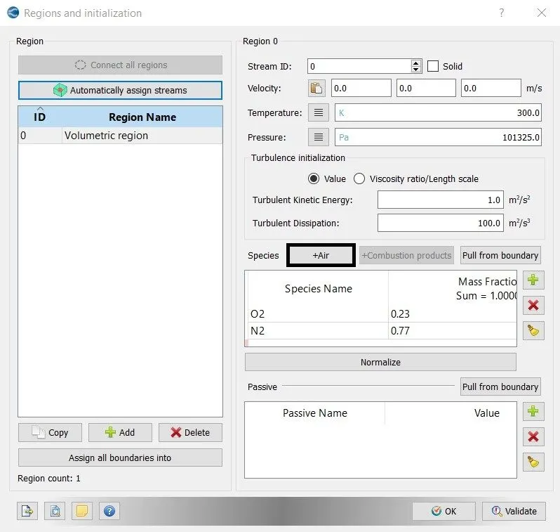
6. Region and Initialization:-
7. Boundary Conditions:-
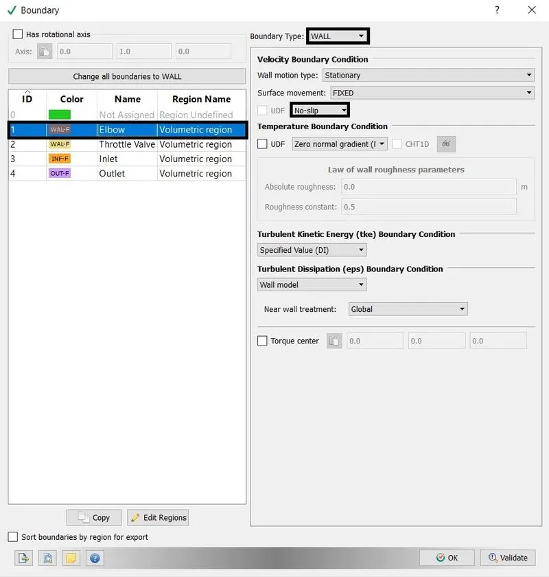
- Elbow = wall with No-slip boundary condition.
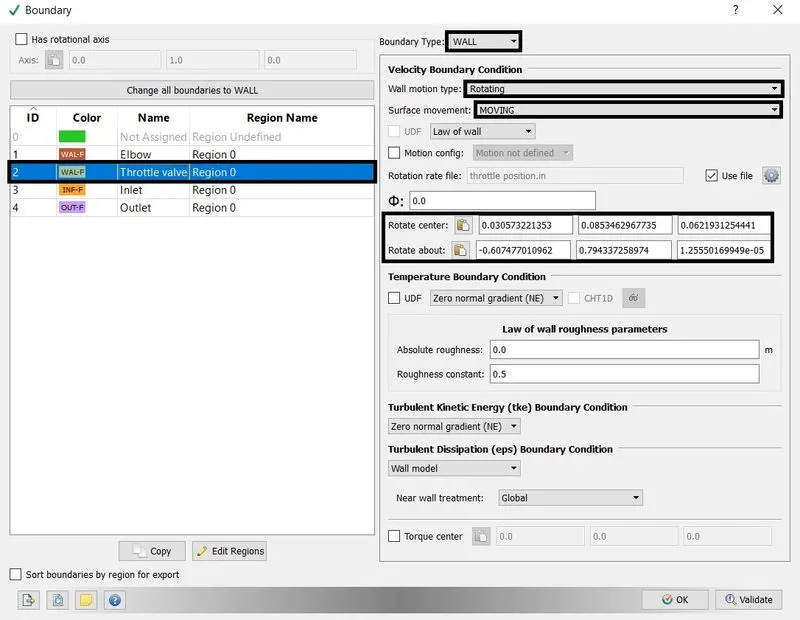
- Throttle Valve = wall with rotating and moving condition.
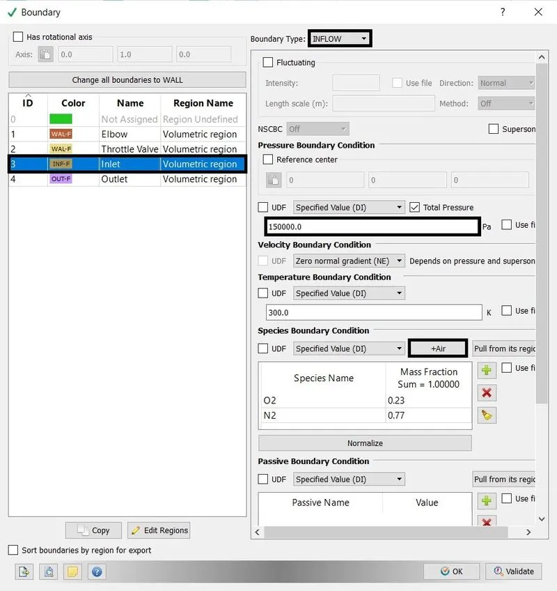
- Inlet = Inflow with pressure of 150000 Pa.
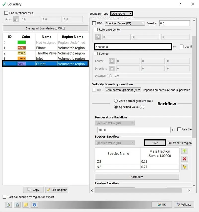
- Outlet = Outflow with pressure of 100000 Pa.
Elbow:-
Throttle Valve:-
Inlet:-
Outlet:-
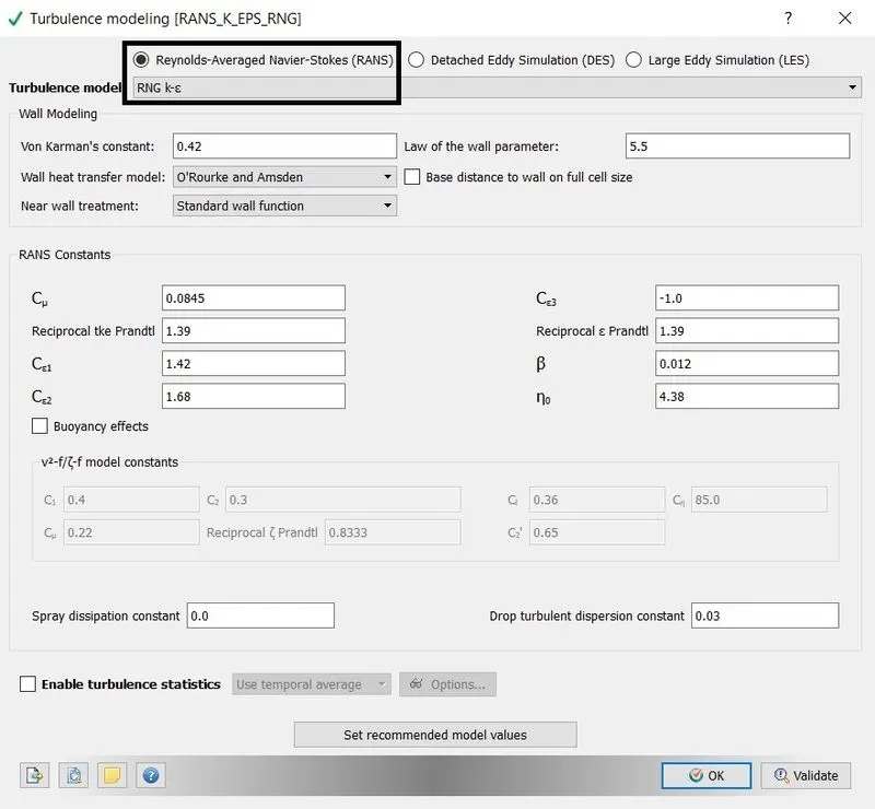
8. Physical model:-
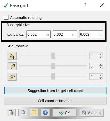
9. Grid control:-
- Base grid
- Fixed Embedding.

10. Output/Post-processing:-
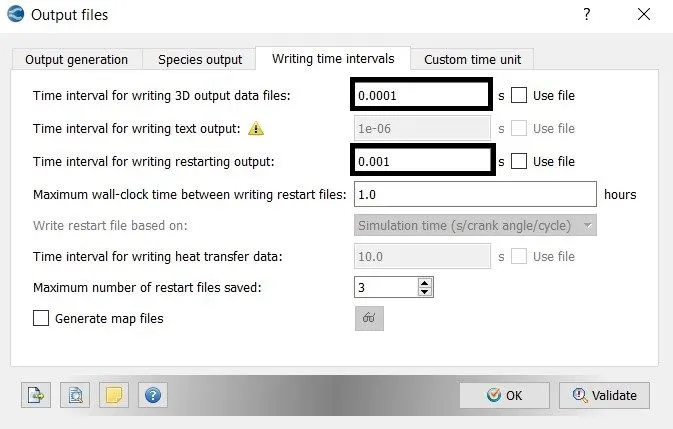
writing time interval for output data file is 0.0001 s that will generate 100 output files.
`"Output Files" = "End time"/"Time interval for writing output data"`
`"Output File" = 0.01/0.0001`
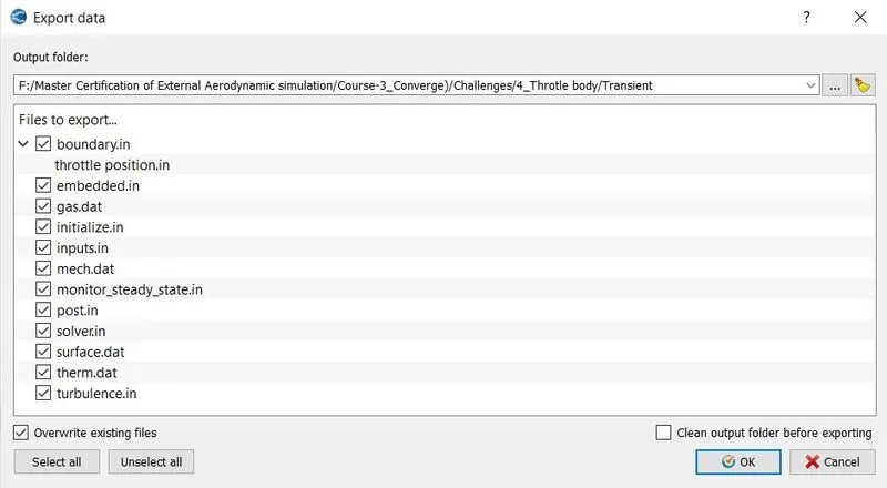
11. Export data:-
C. Execute the simulation:-
- The Executable file "mpiexec.exe" and "converge.exe" are pasted in the input files.
- To run the simulation in Cygwin by using the command.
mpiexec.exe -n 2 converge.exe restricted </dev/null> logfile &
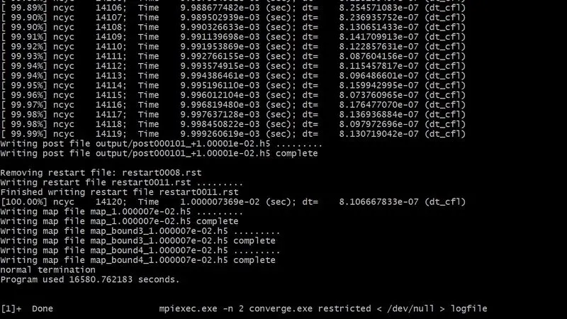
Time taken = 16580.76 seconds or 4.60 hours
After the simulation is complete, the output files can be converted into paraview VTK in-line binary format to Post-process the result in paraview.
mpiexec.exe -n 2 post_convert_30_msmpi.exe
D. Post-Processing the result in Paraview:-
1. Mesh:-
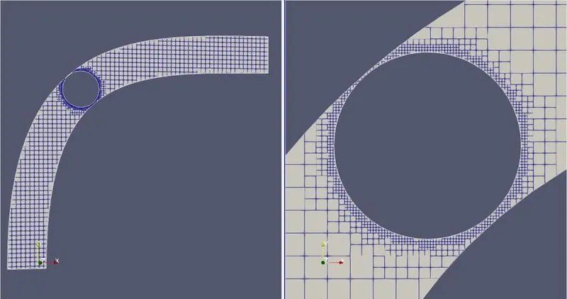
Fig(a). Mesh with 0 millisecond.
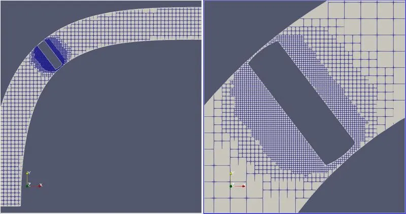
Fig(a). Mesh with 1 millisecond.
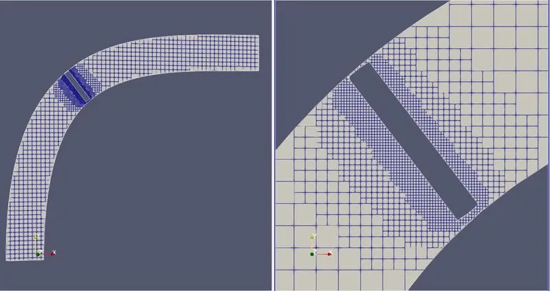
Fig(a). Mesh with 2 millisecond.
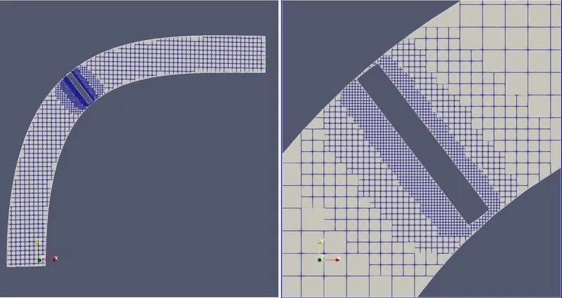
Fig(a). Mesh with 4 millisecond.
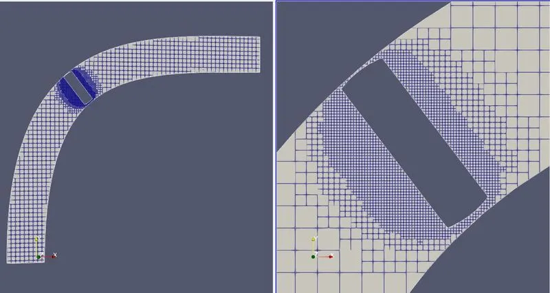
Fig(a). Mesh with 6 millisecond.
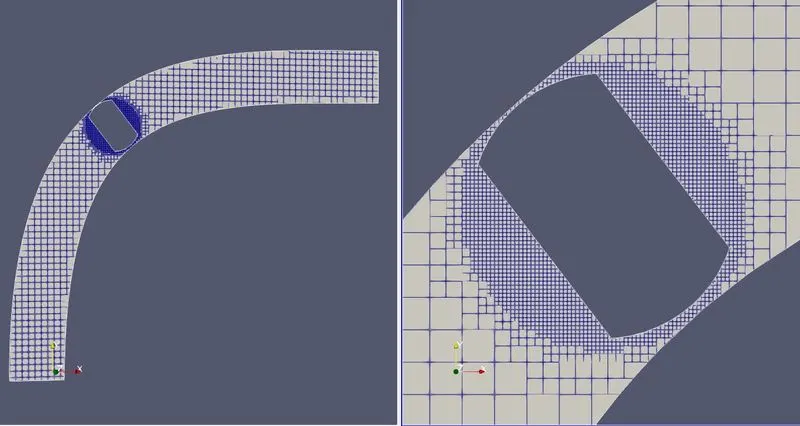
Fig(a). Mesh with 7 millisecond.
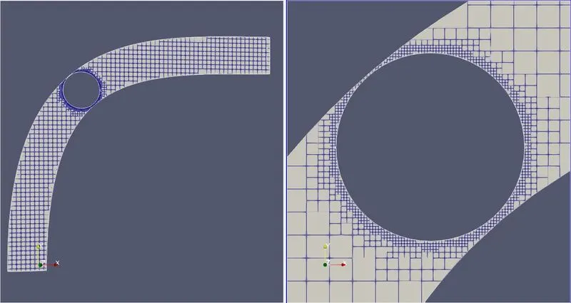
Fig(a). Mesh with 8 millisecond.
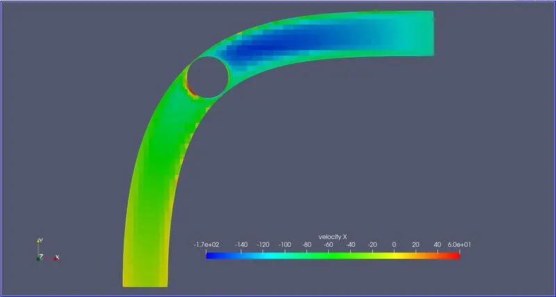
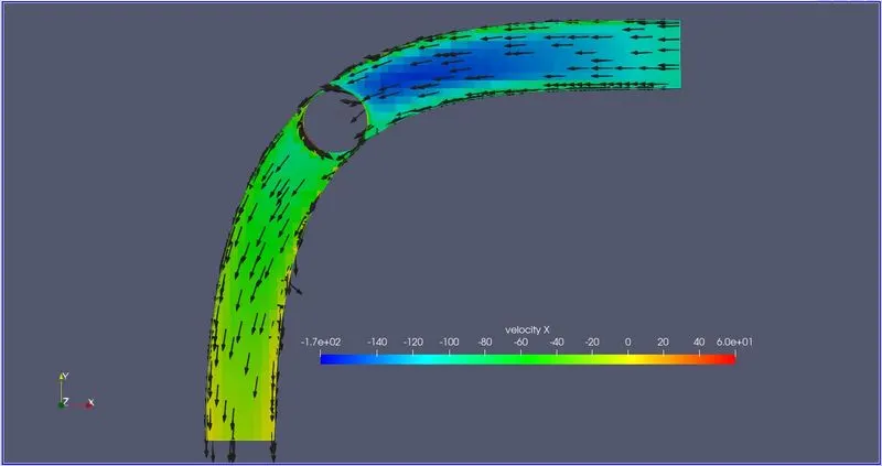
2. Velocity Contour:-
3. Pressure Contour:-
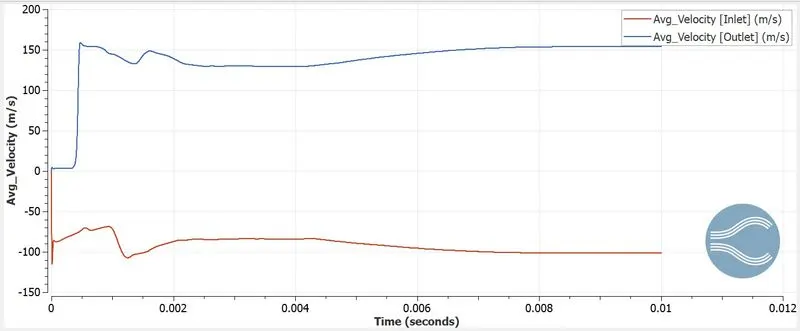
4. Average Velocity line plot:-
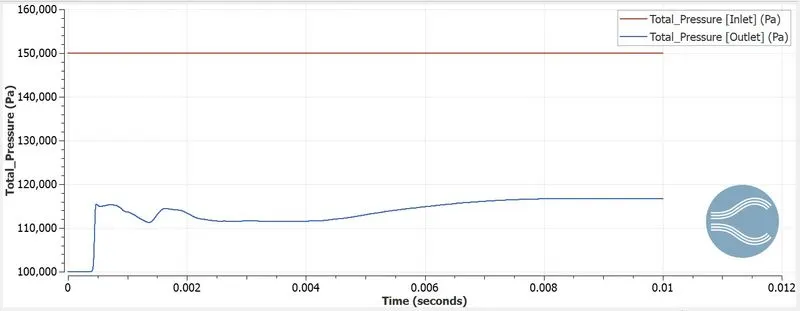
5. Total pressure line plot:-
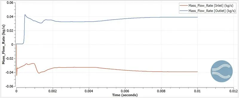
6. Mass Flow Rate line plot:-
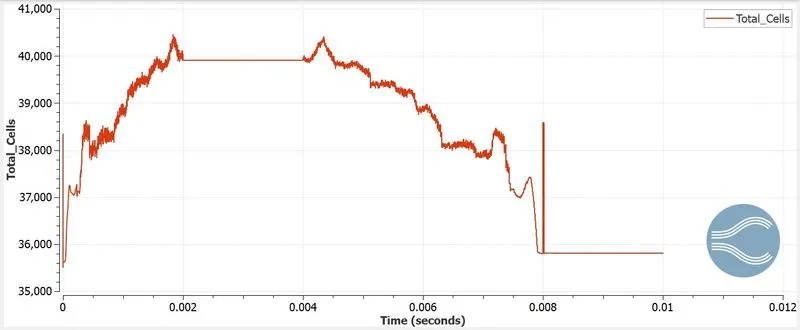
7. Total Cell count:-
8. Animation:-
Velocity Streamline:-
Velocity:-
Pressure:-
E. Conclusion:-
- In a Transient-state simulation, the flow of air is observed in the throttle body with different profile angle of throttle valve.
- The different variable is measured when throttle valve is rotating at 25 degree and return to its original position within 10 millisecond.
0-2 millisecond > rotate by 25 degree
2-4 millisecond > stay at 25 degree
4-8 millisecond > return to its original position
- The mass flow rate at 4 millisecond is 0.035 kg/s and after 8-10 millisecond it is 0.04 kg/s. The valve is partially closed at 4 millisecond so the mass flow rate is less.
- The Pressure and velocity is also increased after the 4 millisecond.
- The Pressure is high in the inlet of the elbow and the inlet throttle valve region.
- The Velocity is high in the outlet of the elbow and the outlet throttle valve region.
- The Bernoullis formula explains the relation of pressure and velocity is inversely proportional. It means that when pressure increases, the velocity decreases, keeping the algebric sum of potential energy, kinetic energy and pressure constant.
- The total cell value is changing when the throttle valve is rotating.
0 millisecond = 35518
2 - 4 millisecond = 39907
6 millisecond = 38868
8 -10 millisecond = 35808
The above cell value is taken from cell_count_ranks.out file.