Week 9 - Mini project - Flow over an Airfoil
FLOW OVER AN AIRFOIL (NACA 2412)
Aim:-
To analyse the flow over an Airfoil (NACA 2412) and calculate drag coefficient (Cd) and Lift coefficient (Cl).
Objective:-
- Drag coefficient vs Angle of attack
- Lift coefficient vs Angle of attack
- Compare the effects of the turbulence model on the above two results.
- The Inlet Reynolds number is 200,000
- Calculate the Angle of attack for 1°, 5°, 10°, 15°.
Theory:-
Airfoil:-
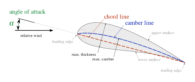
Airfoil also spelled Aerofoil, shaped surface such as an aeroplane wing, tail or propeller blade, that produces lift and drag when moved through the air. An airfoil produces a lifting force that acts at right angles to the airstream and a dragging force that acts in the same direction as the airstream. An Airfoil-shaped wing can create downforce on an automobile or other motor vehicle, improving traction.
1. Calculation for Inlet Velocity:-
`color(red) (Re = (rho*v*L)/(mu))`
where,
`Re` = 200000 (Reynolds number)
`rho` = 1.1761 `Kg//m^3`(Density of the air at 30°C)
`v` = Velociy of the air`m//s`
`mu` = 0.00001846 `Kg//m.s` (Dynamic viscosity of the air at 30°C)
`v = (Re*mu)/(rho*L)`
`v = (200000xx0.00001846)/(1.1761xx0.1)`
`v = 3.692/0.11761`
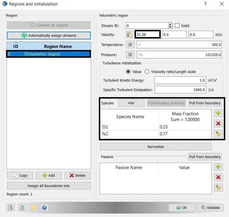
`v = 31.39 m/s`
2. End Time Calculation:-
`color(red)("Flow through times" = ("Distance travelled by the fluid from Inlet to Outlet")/("Inlet Velocity")`
`"Flow through times" = 2/31.39`
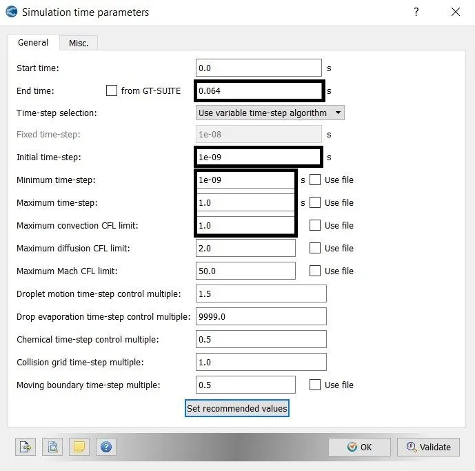
`Flow through times = 0.0637 s ~~ 0.064 s`
`therefore "End time" = 0.064s`
Turbulence Model:-
The Simulation is run with the following turbulent model and angle of attack
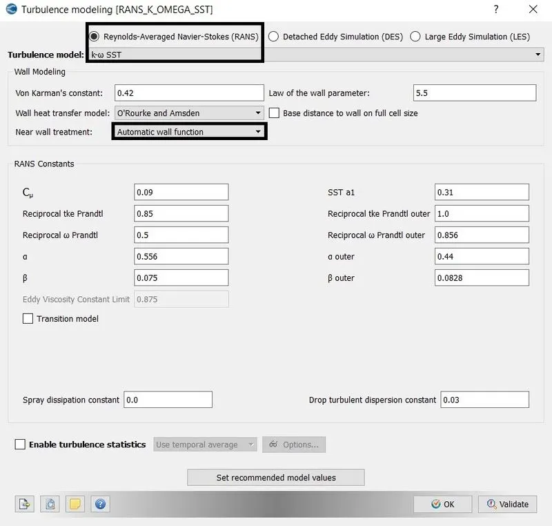
1.`k-omega` SST with Automatic wall function
- Angle of Attack 1°
- Angle of Attack 5°
- Angle of Attack 10°
- Angle of Attack 15°
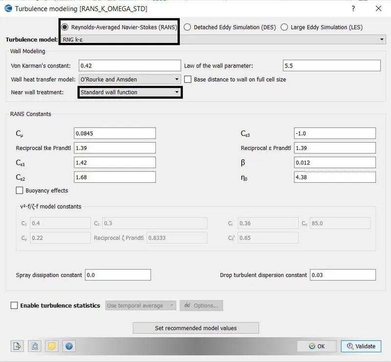
2. RNG `k-epsilon` with standard wall function
- Angle of Attack 1°
- Angle of Attack 5°
- Angle of Attack 10°
- Angle of Attack 15°
Simulation Process
Geometry Preparation:-
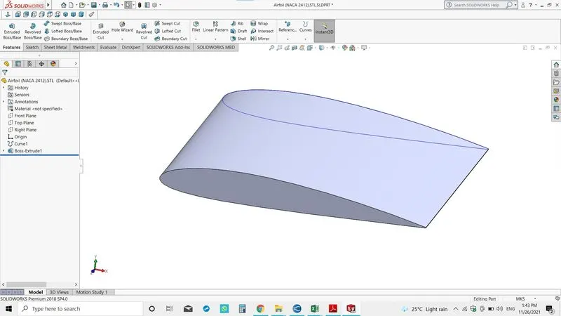
- The NACA 2412 Airfoil model is used in this simulation. The airfoil is created in SolidWorks using the dat file of the NACA Airfoil 2412.
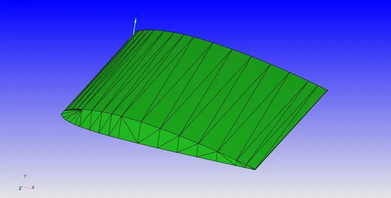
- The model is saved in STL file format to open the model in converge studio.
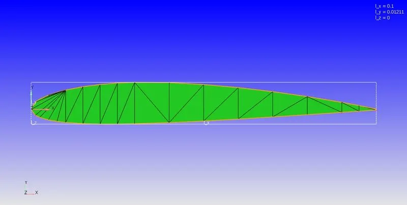
- As per the condition, the chord length should be 0.1m, but the actual length is 1m. So the airfoil scaled to 0.1m.
- The wind tunnel is created for 20 times chord length in X and Y direction from the origin of the airfoil.
- After creating the wind tunnel the boundary condition is flagged.
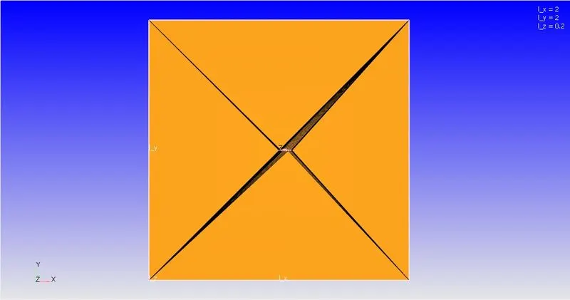
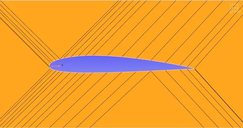
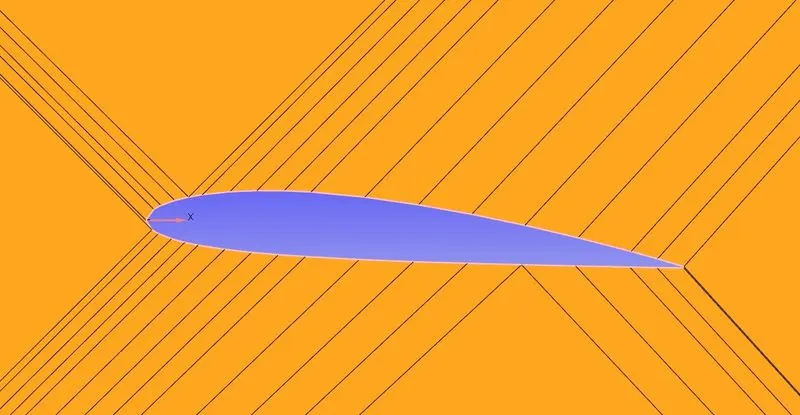
Fig(a). Angle of attack 1° Fig(b). Angle of attack 5°
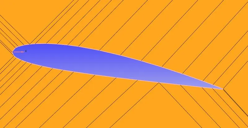
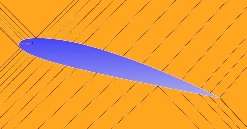
Fig(c). Angle of attack 10° Fig(d). Angle of attack 15°
B. Case Setup:-
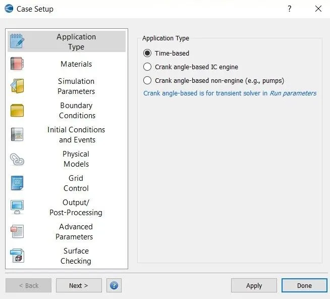
1. Application Type:-
2. Material:-
- Gas Simulation - Redlich-Kwong
- Global transport parameters
- Reaction mechanism - O2 and N2
3. Simulation Parameters:-
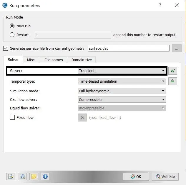
- Run parameters
- Simulation time parameters
- Solver parameters - PISO (Density-based solver)
4. Initial Conditions and Events:-
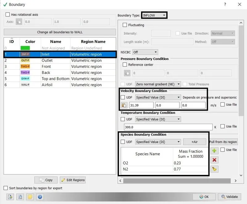
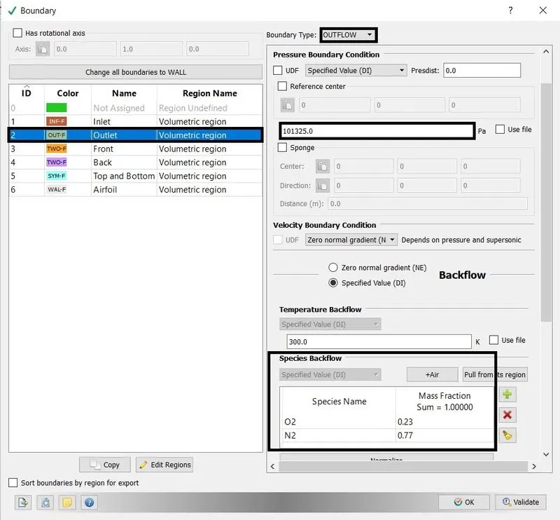
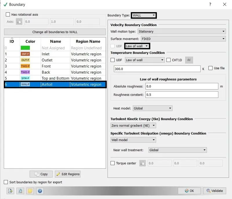
5. Boundary Condition:-
- Inlet - Inflow
- Outlet - Outflow
- Airfoil - Wall
- Front and Back - Two_D
- Top and bottom - Symmetry
6. Physical models:-
- `k-omega` SST with Automatic wall function
- RNG `k-epsilon` with standard wall function
7. Grid Controls:-
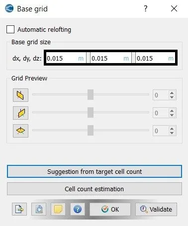
- Base Grid
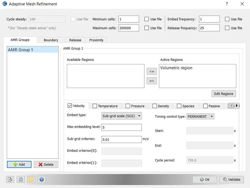
- Adaptive Mesh Refinement (AMR)
8. Output/Post-Processing:-
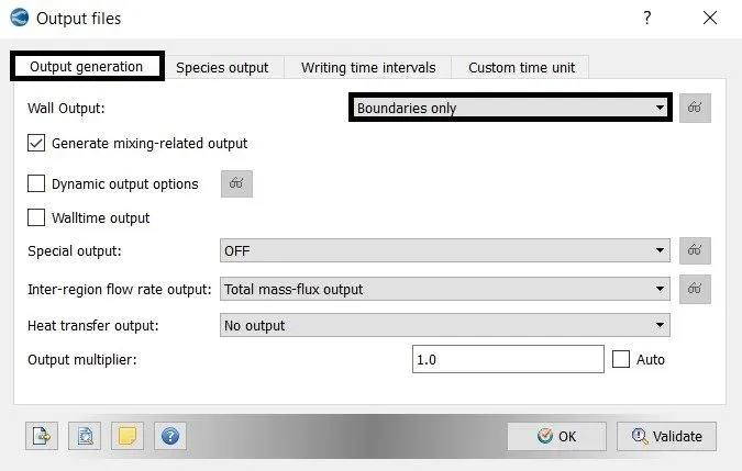
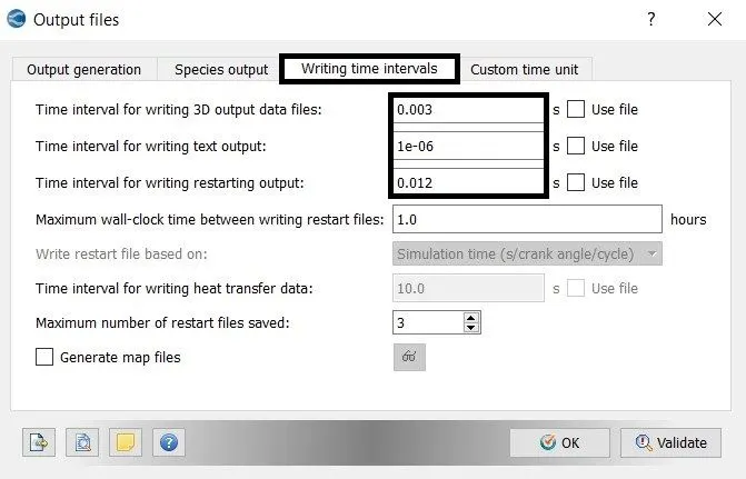
C. Execute the Simulation:-
- The Executable file "mpiexec.exe" and "converge.exe" is pasted in the input files.
- To run the simulation in Cygwin by using the command
mpiexec.exe -n 2 converge.exe restricted </dev/null> logfile &
- After the simulation is complete, the output files can be converted into Paraview VTK in-line binary format to post-process the result in Paraview.
mpiexec.exe -n 2 post_convert_30_msmpi.exe
D. Post-Processing the Result:-
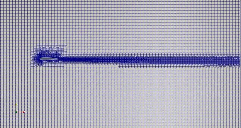
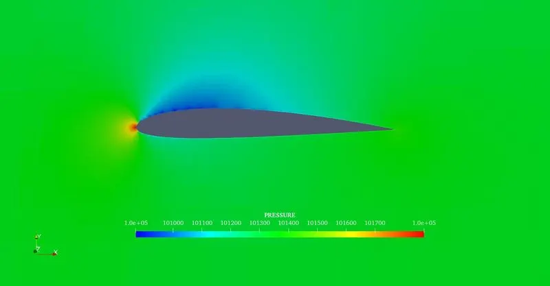
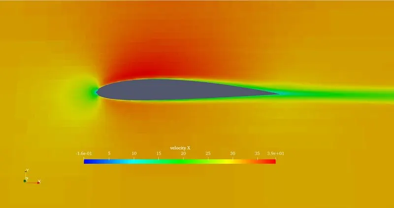
Case 1: Angle of Attack 1° (K- Omega SST)
1. Mesh:-
2. Pressure Contour:-
3. Velocity Contour:-
4. Animation
Case 2: Angle of Attack 5° (K- Omega SST)
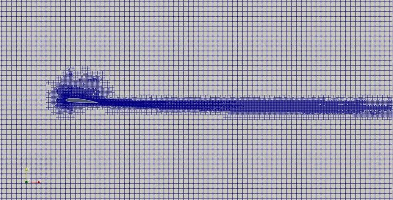
1. Mesh:-
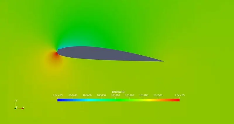
2. Pressure Contour:-
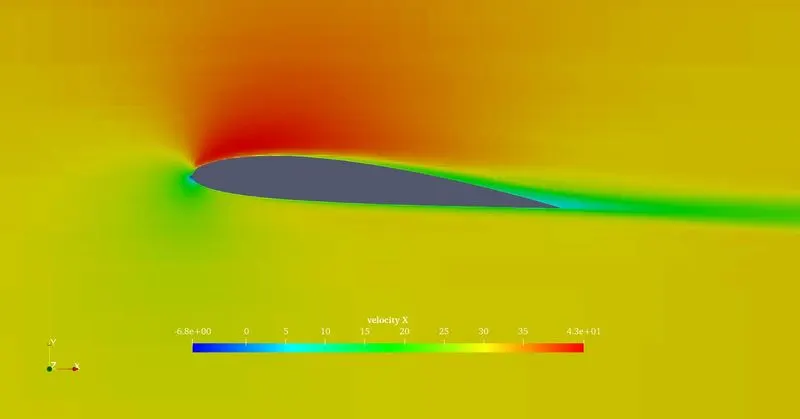
3. Velocity Contour:-
4. Animation:-
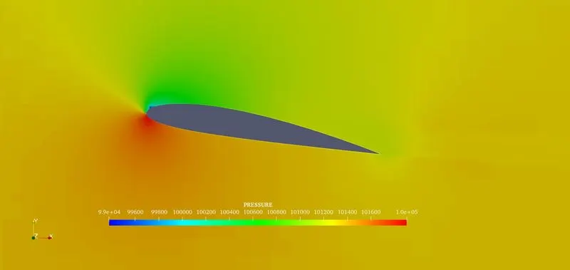
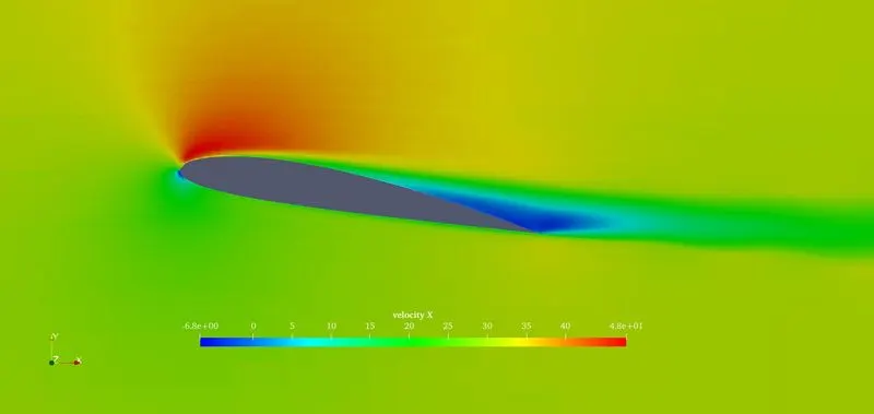
Case 3: Angle of Attack 10° (K- Omega SST)
1. Mesh:-
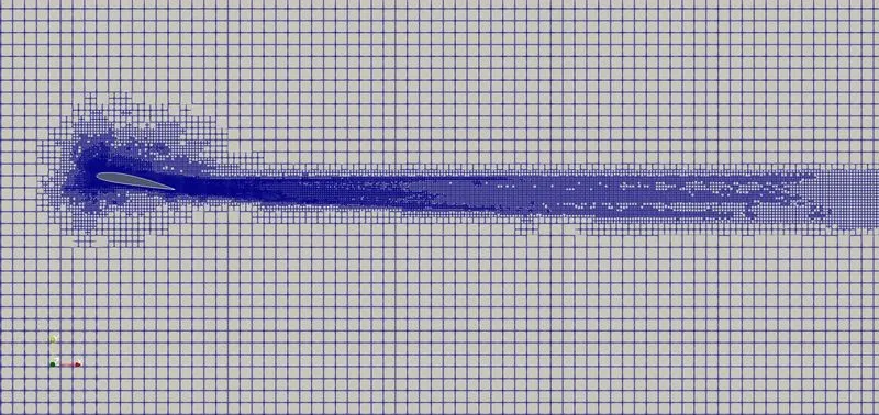
2. Pressure Contour:-
3.Velocity Contour:-
4. Animation:-
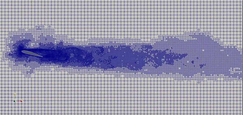
Case 4: Angle of Attack 15° (K- Omega SST)
1. Mesh:-
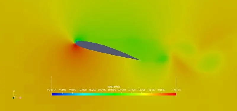
2. Pressure Contour:-
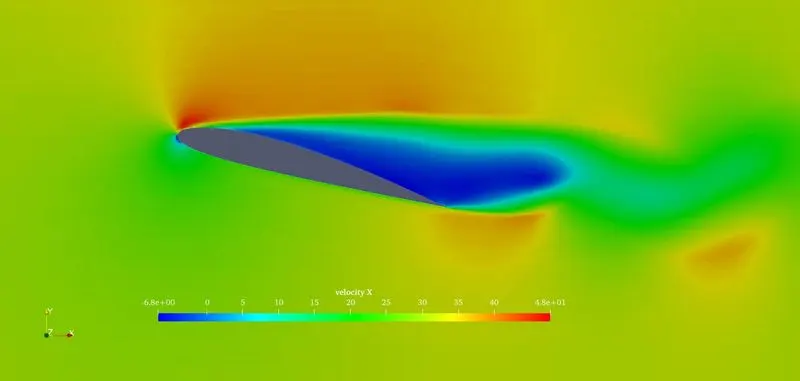
3. Velocity Contour:-
4. Animation:-
*****************************************************************************************
Drag and Lift Coefficient Calculation:-
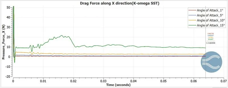
1. `color(red)("Drag Coefficient" =(F_D)/((rho*A*v^2)/(2)))`
2. `color(red)("Lift Coefficient" =(F_L)/((rho*A*v^2)/(2)))`
Where,
`F_D` = Drag Force `N`
`F_L` = Lift Force `N`
`rho` = Density of Air `Kg//m^3` = 1.1761
A = Area of the Airfoil `m^2` = 0.04
v = Velocity of the air `m//s` = 31.39
`(rho*A*v^2)/2 = (1.1761xx0.04xx(31.39)^2)/(2)`
`(rho*A*v^2)/(2) = color(blue)(23.175) N`
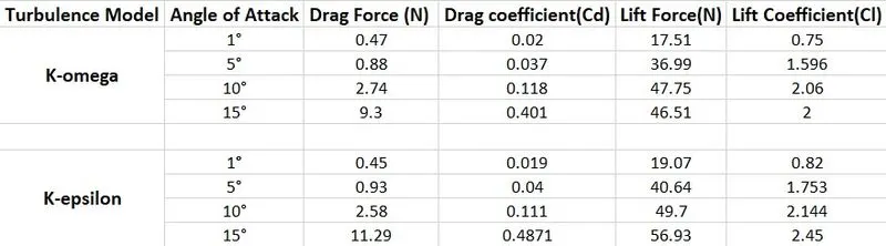
Drag Coefficient (Cd) = `0.47/23.175 = 0.02`
Lift Coefficient (Cl) = `(17.51)/(23.175) = 0.75`
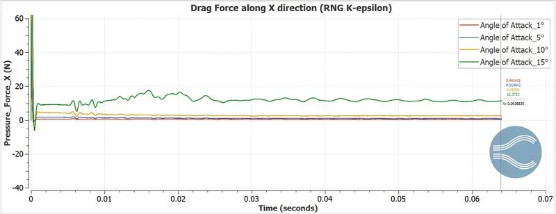
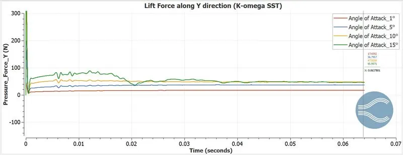
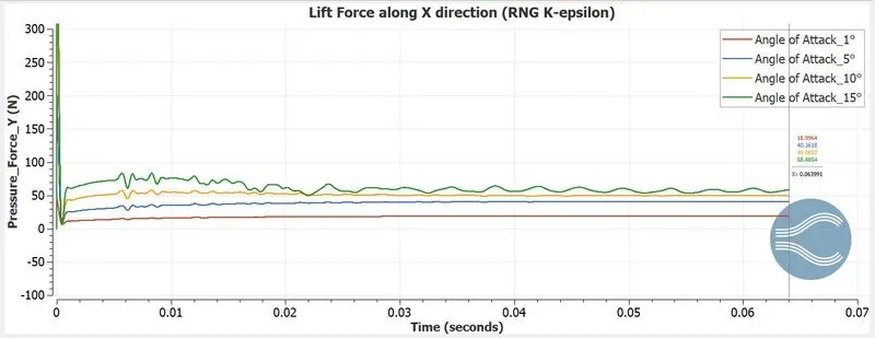
The drag and lift coefficient of all angles for both turbulence models is calculated from the above procedure.
1. Drag Force:-
2. Lift Force:-
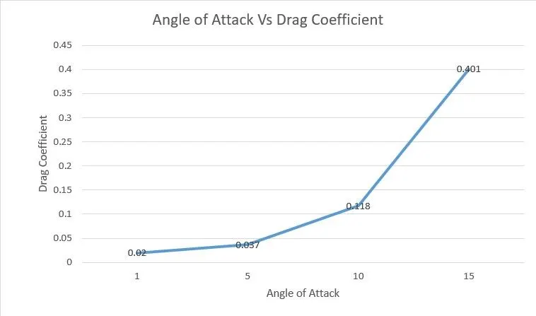
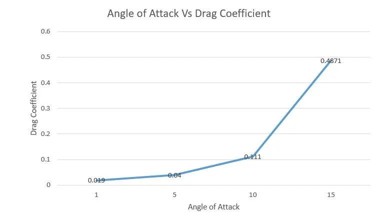
3. Angle of Attack Vs Drag Coefficient:-
- K-Omega SST:-
- RNG K-epsilon:-
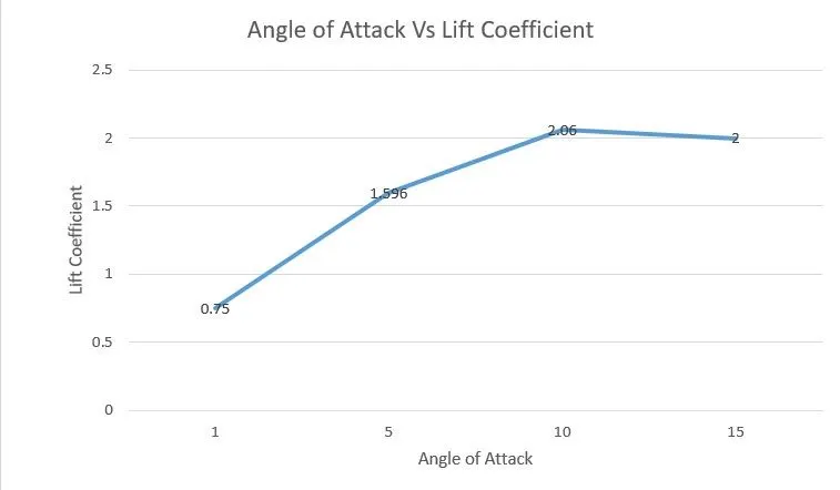
4. Angle of Attack Vs Lift Coefficient:-
- K-Omega SST:-
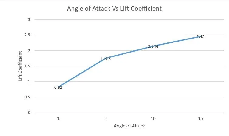
- RNG K- epsilon:-
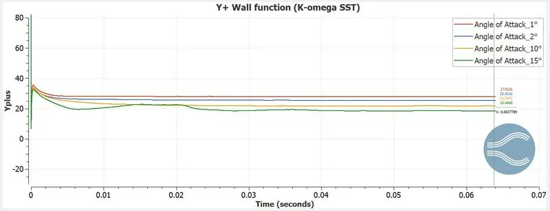
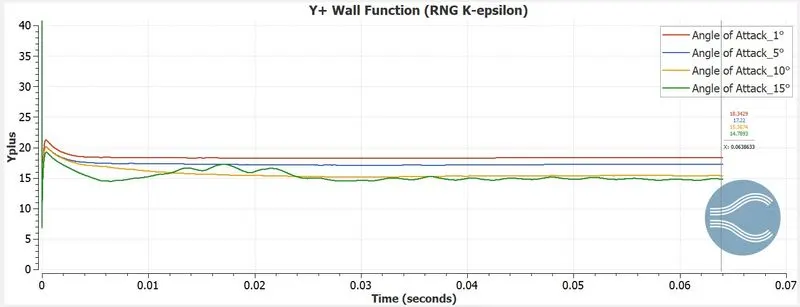
5. Y+ Wall Function:-
E. Conclusion:-
- In the Airfoil simulation, the transient solver is used.
- The Lift and Drag coefficient is analysed with respect to the angle of attack and turbulence model.
- In both turbulence models, the Drag Coefficient is gradually increased.
- In K-epsilon the Lift coefficient is gradually increased. But in the k-omega, the lift coefficient is increased to the angle of attack 10° and dropped at 15°.
- So from the K-epsilon, the Lift coefficient is maximum at the Angle of attack 10°. Because in K-epsilon the automatic wall function is used.
- The vortex shedding is created at the angle of attack 15°.
- The base mesh size is 0.15m and Adaptive mesh refinement(AMR) with an embedding level of 5 is used in all the simulations.
- The Pressure and velocity are high at the leading edge of the airfoil
- The wall output file is imported to excel and the pressure forces X and Y are averaged to the last 1000 iteration.