Week 6 - CHT Analysis on a Graphics card
CHT Analysis on Graphics Card
Aim:
To Perform the Steady-State conjugate heat transfer analysis on a graphics card model with the appropriate fluid and solid material for the simulation.
Objective:
- Run the simulation by varying the velocity from 1 m/s to 5 m/s for at least 3 velocities and discuss the results.
- Find out the maximum temperature and heat transfer coefficient attained by the processor.
- Prove that the simulation has achieved convergence with appropriate images and plots.
- Identify the potential hotspot on the model.
Theory:
Conjugate Heat Transfer Analysis:-
The Conjugate Heat Transfer analysis type allows for the simulation of heat transfer between solid and fluid domains by exchanging thermal energy at the interfaces between them. Typical application of this analysis type exist as, but are not limited to, the simulation of heat exchangers, cooling of electonic equipment, and general-purpose cooling and heating systems.
Simulation process:
- Case 1 - Baseline mesh with velocity 1 m/s.
- Case 2 - Refined mesh with velocity 1 m/s
- Case 3 - Refined mesh with velcity 3 m/s.
- Case 4 - Refined mesh with velocity 5 m/s.
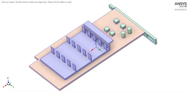
Geometry(SpaceClaim).
- In a SpaceClaim the given graphics card model has been loaded as a stp file.
- The geometry has a part of Base, Processors, Fins, Enclosure.
- All the model could been shared topology for the conformal mesh.
- After shared the model the pink outline on the geometry to conform it has been shared.
Base:-
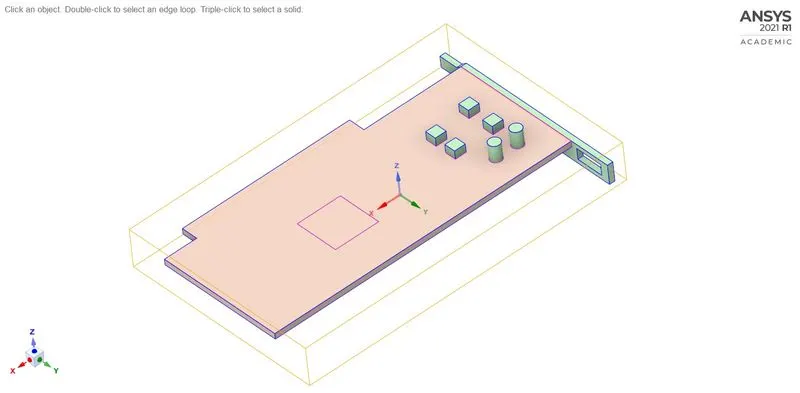
Processor:-
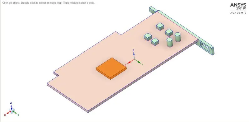
Fins:-
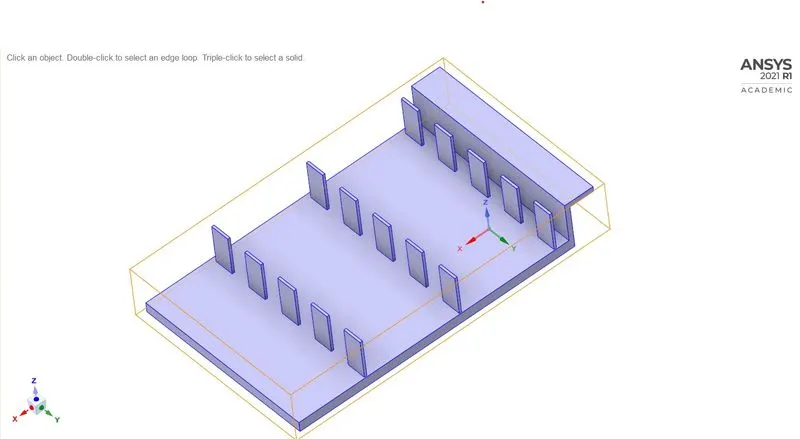
Enclosure:-
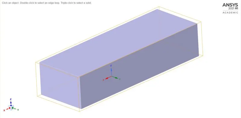
All components without enclosure:-
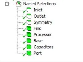
Named Selection.
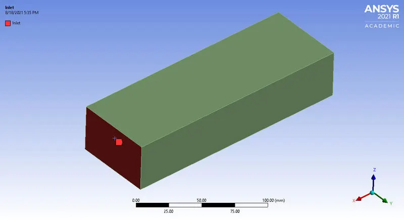
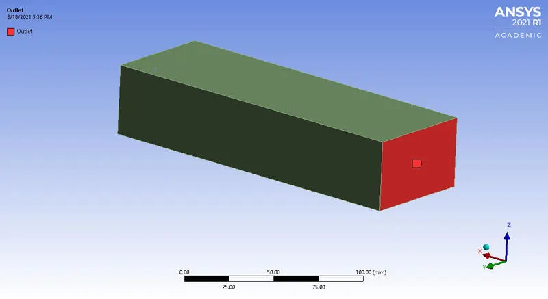
Fig(1). Inlet Fig(2). Outlet
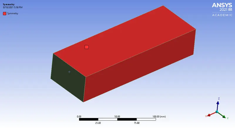
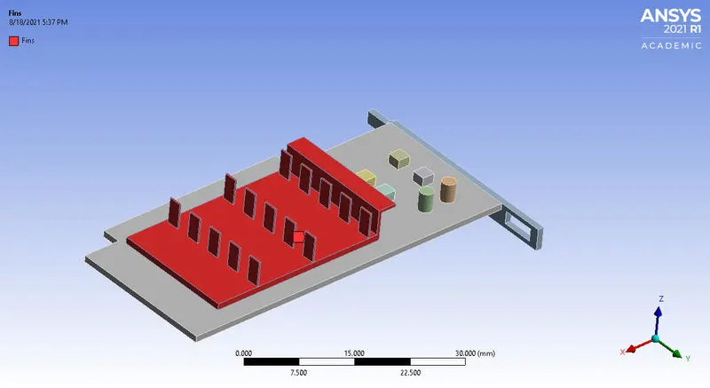
Fig(3). Symmetry Fig(4). Fins
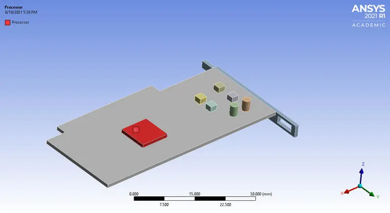
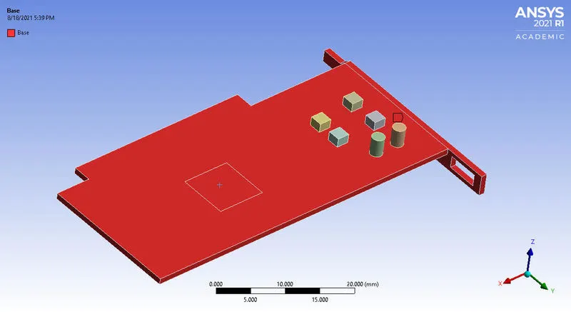
Fig(5). Processor Fig(6). Base
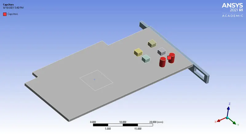
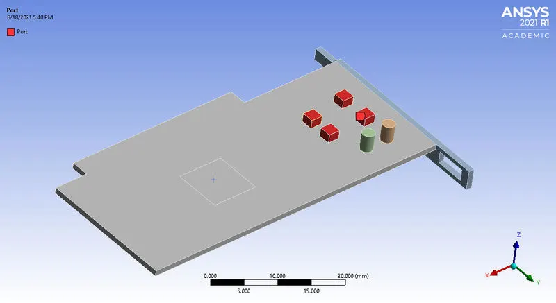
Fig(7). Capacitors Fig(8). Port
\*********__________**********__________*********__________*********__________*********__________*********__________*********__________*********/
Case 1 - Baseline mesh with velocity 1 m/s.
1. Meshing:-
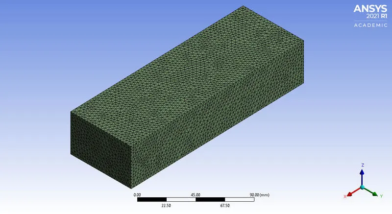
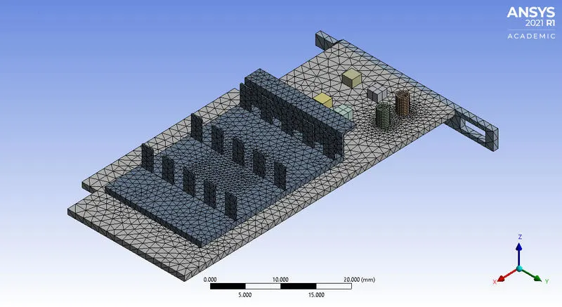
Fig(a). Enclosure Mesh Fig(b). Body Mesh of Fins
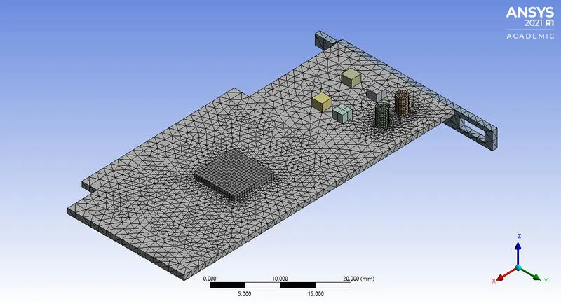
Fig(c). Body Mesh of Processor and Base.
Detail of Mesh:-
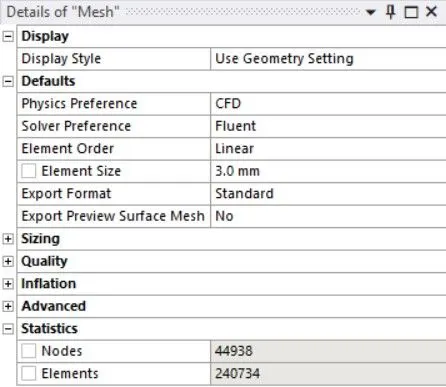
- Element size for Enclosure = 3 mm.
- Element size for Processor = 0.5 mm
- Element size for Fins = 1 mm.
- Element size for Base = 1.5 mm.
- Nodes = 44938
- No of Elements = 240734
2. Fluent Setup & Solving.
- Enable energy equation
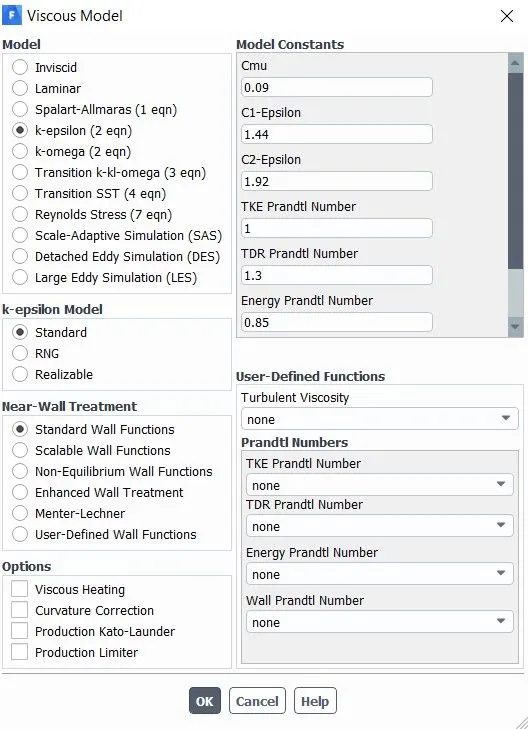
- Viscous model = k - epsilon, standard.
Material:-
Fluid.
- Air
Solid.
- Aluminum
- Copper
- Steel
- Wood
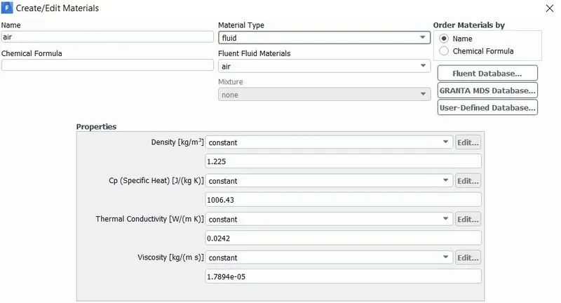
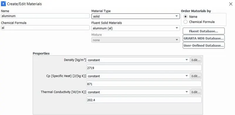
Fig(1). Air Fig(2). Aluminum
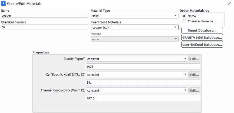
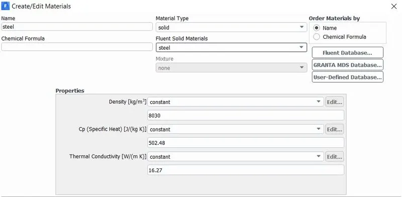
Fig(3). Copper Fig(4). Steel
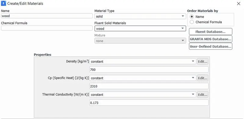
Fig(5). Wood
Cell Zones:-
- Enclosure - Air
- Base - Wood
- Fins - Copper
- Capacitors - Steel
- Port - Steel
- Processor - Aluminum with (source term = 312500000 `W//m^3`)
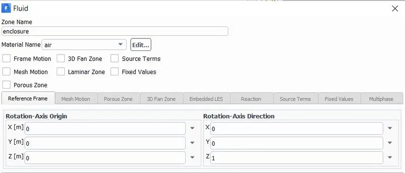
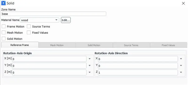
Fig(1). Air Fig(2). Wood
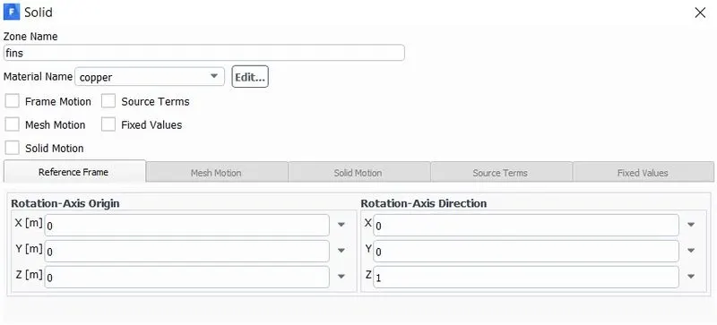
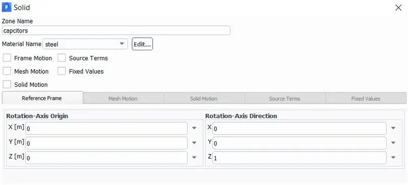
Fig(3). Copper Fig(4). Steel(capacitors)
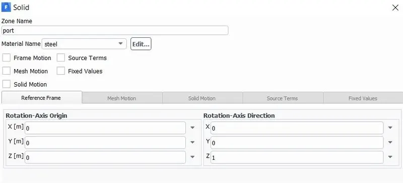
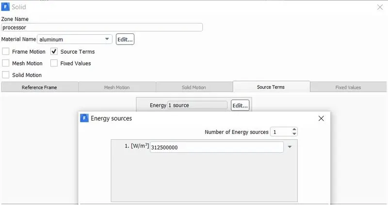
Fig(5). Steel(port) Fig(6). Aluminum
Calculation of Power source:-
`"Source" = ("Power of the processor (W)")/("Volume of the processor (m^3)")`
`"Source" = 20/0.000000064`
`"Source" = "312500000 W/m^3"`
Note:- The processor power 20 watts is assumed.
Boundary condition:-
- Inlet Velocity = 1 m/s.
Residuals:-
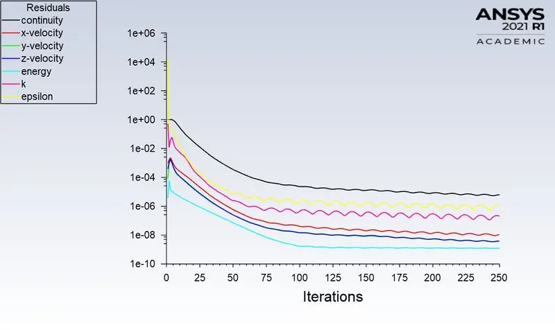
The solution is converged after the 70th iteration.
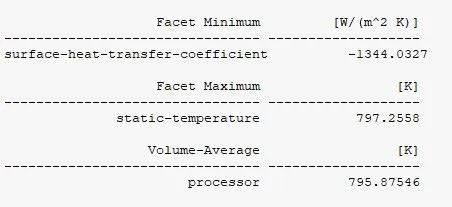
Facet Minimum:-
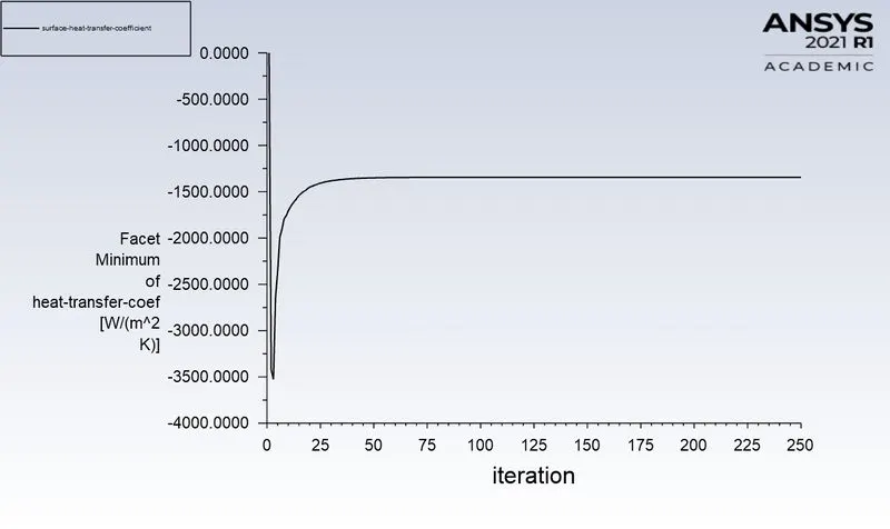
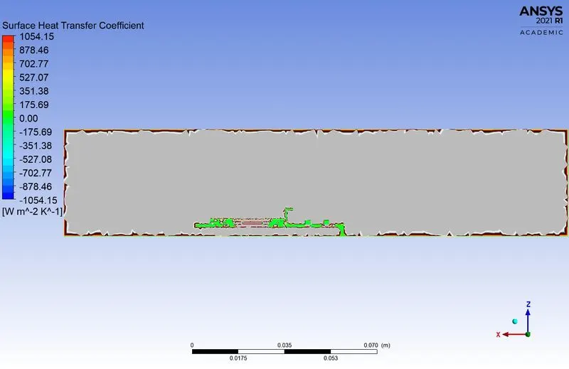
Surface Heat transfer coefficient = -1344.0327 [ `W//m^2.K`]
Facet Maximum:-
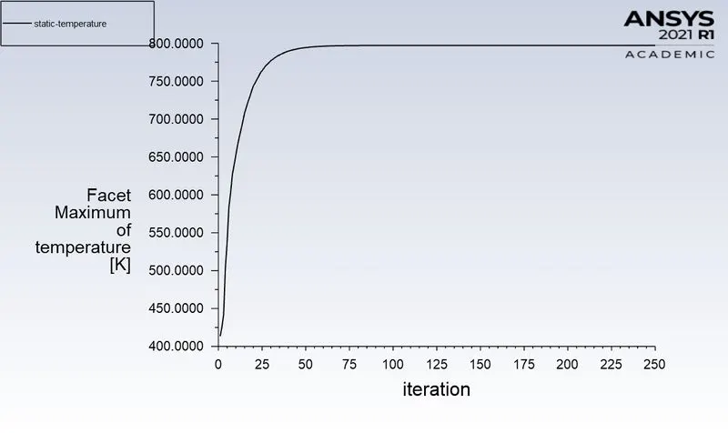
Static Temperature = 797.2558 K.
Volume Average:-
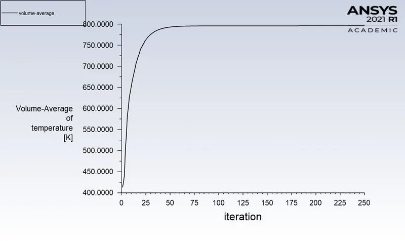
Average volume temperature in processor = 795.87546 K.
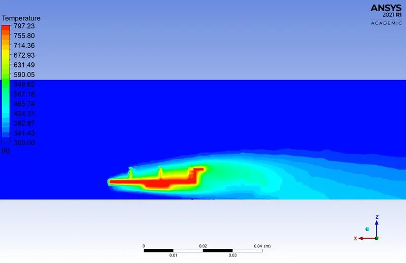
3. CFD Post-Processing Result.
Temperature contour:-
Velocity Contour:-
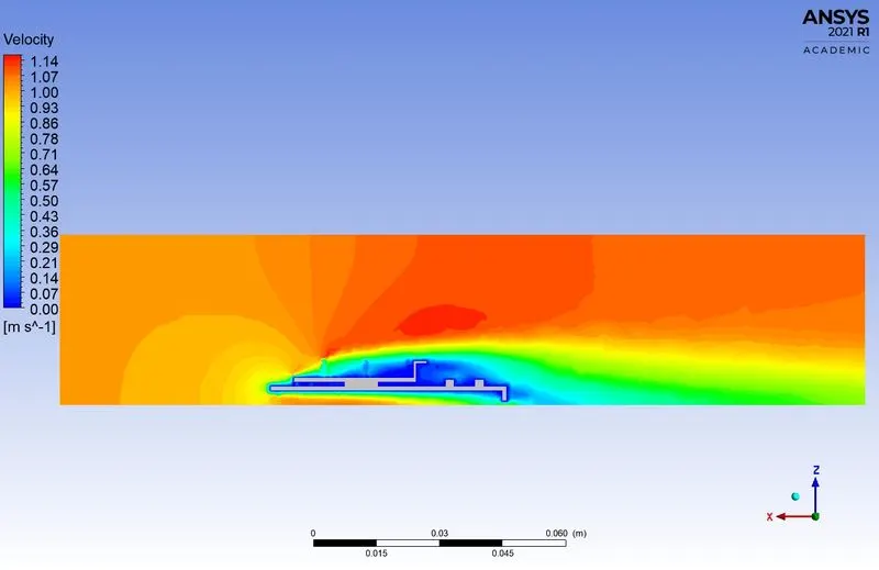
Surface Heat Transfer Coefficient:-
\*********__________**********__________*********__________*********__________*********__________*********__________*********__________*********/
Case 2 - Refined mesh with velocity 1 m/s.
1. Meshing:-
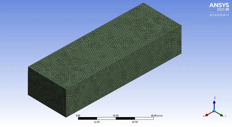
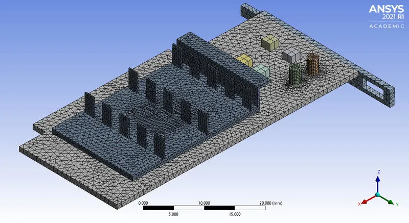
Fig(a). Enclosure Mesh Fig(b). Body Mesh of Fins
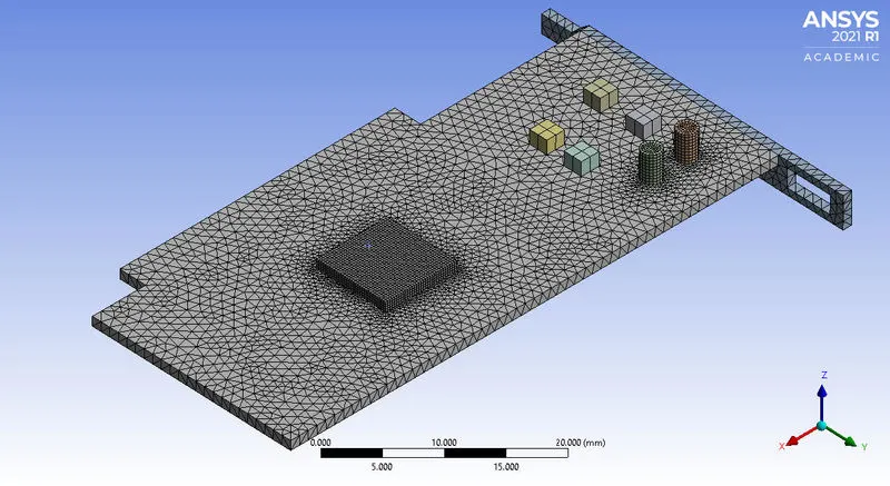
Fig(c). Body Mesh of Processor and Base.
Detail of Mesh:-
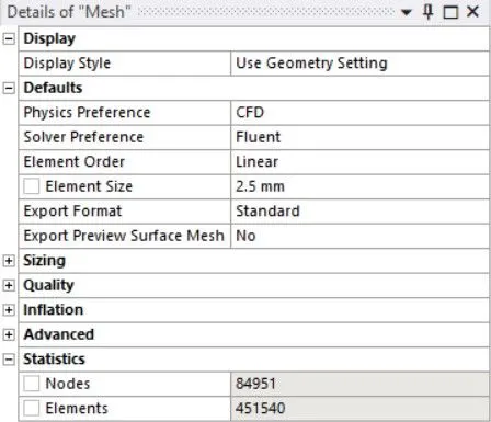
- Element size for Enclosure = 2.5 mm.
- Element size for Processor = 0.25 mm
- Element size for Fins = 0.75 mm.
- Element size for Base = 1 mm.
- Nodes = 84951
- No of Elements = 451540
2. Fluent Setup & Solving.
- Enable energy equation
- Viscous model = k - epsilon, standard.
Material:-
Fluid.
- Air
Solid.
- Aluminum
- Copper
- Steel
- Wood
Fig(1). Air Fig(2). Aluminum
Fig(3). Copper Fig(4). Steel
Fig(5). Wood
Cell Zones:-
- Enclosure - Air
- Base - Wood
- Fins - Copper
- Capacitors - Steel
- Port - Steel
- Processor - Aluminum with (source term = 312500000 `W//m^3`)
Fig(1). Air Fig(2). Wood
Fig(3). Copper Fig(4). Steel(capacitors)
Fig(5). Steel(port) Fig(6). Aluminum
Calculation of Power source:-
`"Source" = ("Power of the processor (W)")/("Volume of the processor (m^3)")`
`"Source" = 20/0.000000064`
`"Source" = "312500000 W/m^3"`
Note:- The processor power 20 watts is assumed.
Boundary condition:-
- Inlet Velocity = 1 m/s.
Residuals:-
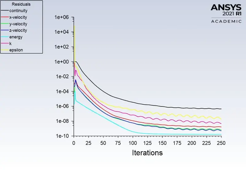
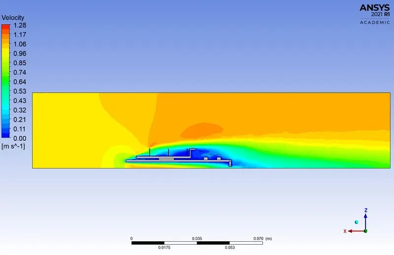
The solution is converged after the 80th iteration.
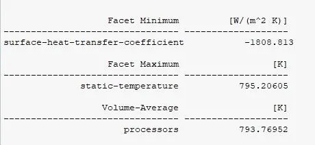
Facet Minimum:-
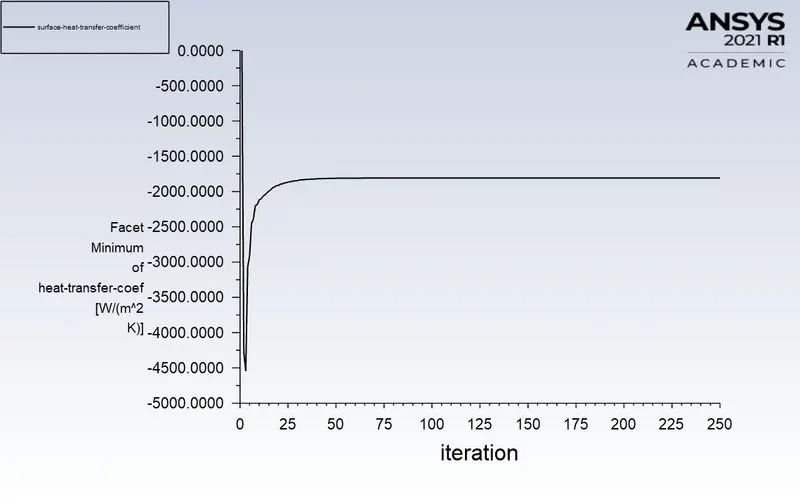
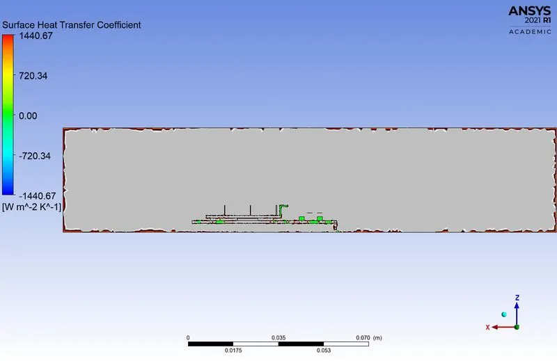
Surface Heat transfer coefficient = -1808.813 [ `W//m^2.K`]
Facet Maximum:-
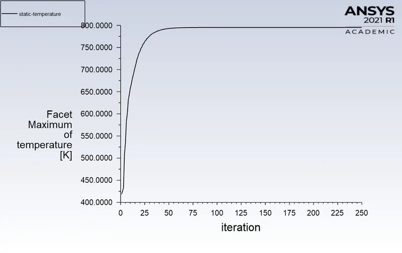
Static Temperature = 795.20605 K.
Volume Average:-
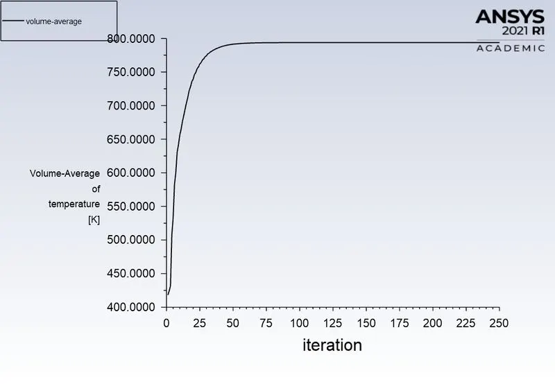
Average volume temperature in processor = 793.76952 K.
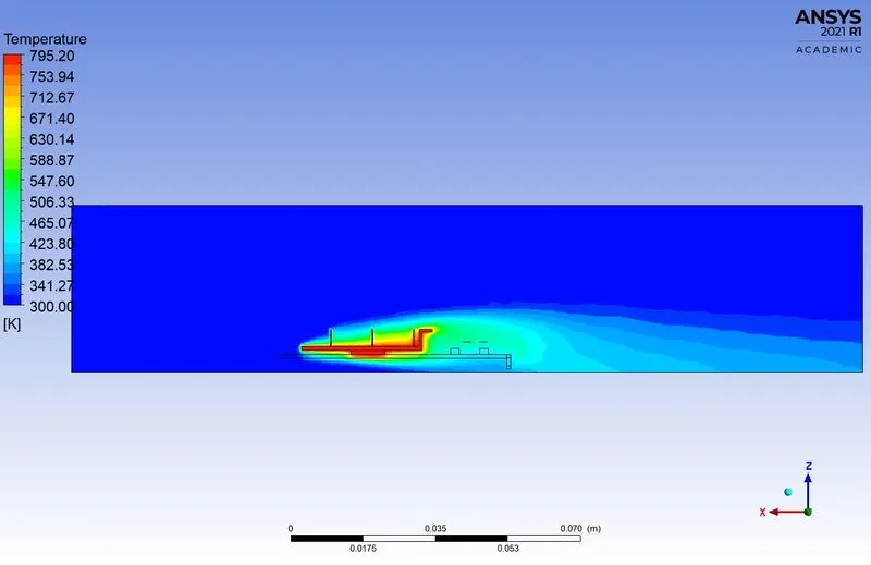
3. CFD Post-Processing Result.
Temperature contour:-
Velocity Contour:-
Surface Heat Transfer Coefficient:-
\*********__________**********__________*********__________*********__________*********__________*********__________*********__________*********/
Case 3 - Refined mesh with velcity 3 m/s.
1. Meshing:-
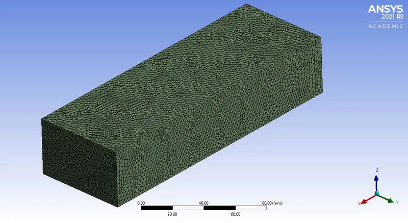
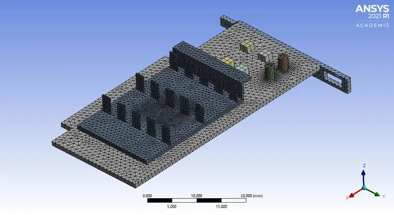
Fig(a). Enclosure Mesh Fig(b). Body Mesh of Fins
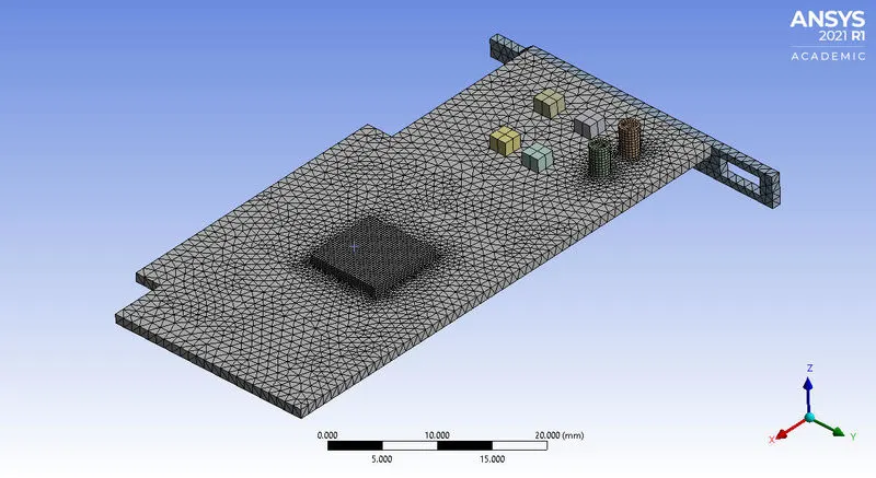
Fig(c). Body Mesh of Processor and Base.
Detail of Mesh:-
- Element size for Enclosure = 2.5 mm.
- Element size for Processor = 0.25 mm
- Element size for Fins = 0.75 mm.
- Element size for Base = 1 mm.
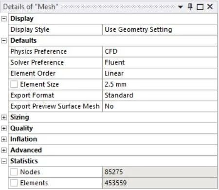
- Nodes = 85275
- No of Elements = 453559
2. Fluent Setup & Solving.
- Enable energy equation
- Viscous model = k - epsilon, standard.
Material:-
Fluid.
- Air
Solid.
- Aluminum
- Copper
- Steel
- Wood
Fig(1). Air Fig(2). Aluminum
Fig(3). Copper Fig(4). Steel
Fig(5). Wood
Cell Zones:-
- Enclosure - Air
- Base - Wood
- Fins - Copper
- Capacitors - Steel
- Port - Steel
- Processor - Aluminum with (source term = 312500000 `W//m^3`)
Fig(1). Air Fig(2). Wood
Fig(3). Copper Fig(4). Steel(capacitors)
Fig(5). Steel(port) Fig(6). Aluminum
Calculation of Power source:-
`"Source" = ("Power of the processor (W)")/("Volume of the processor (m^3)")`
`"Source" = 20/0.000000064`
`"Source" = "312500000 W/m^3"`
Note:- The processor power 20 watts is assumed.
Boundary condition:-
- Inlet Velocity = 3 m/s.
Residuals:-
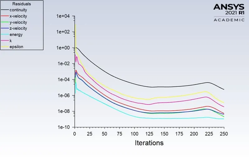
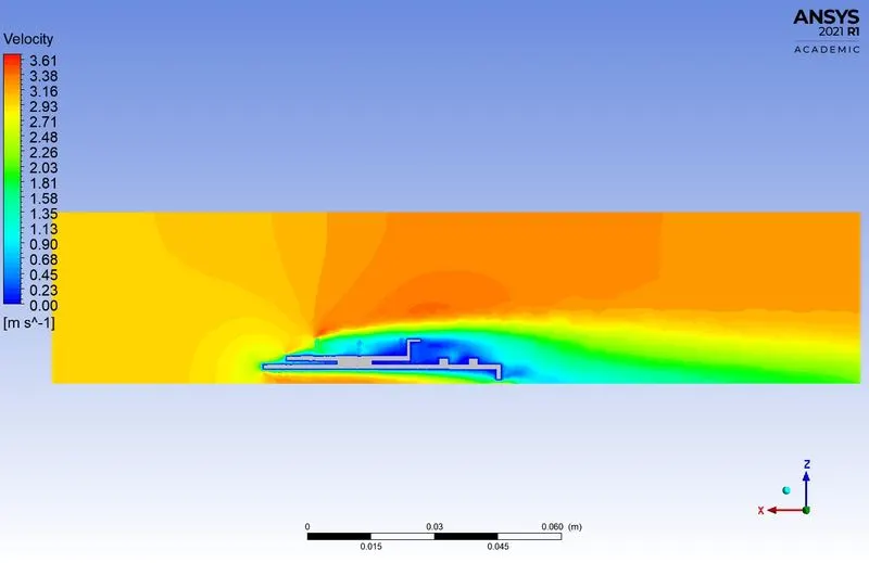
The solution is converged after the 85th iteration.
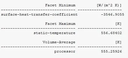
Facet Minimum:-
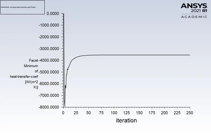
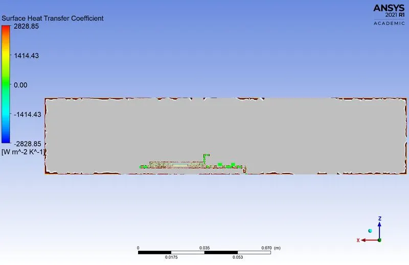
Surface Heat transfer coefficient = -3546.9055 [ `W//m^2.K`]
Facet Maximum:-
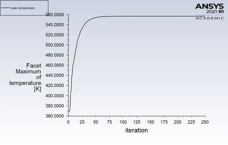
Static Temperature = 556.68402 K.
Volume Average:-
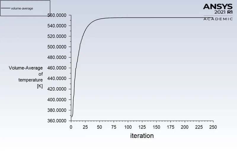
Average volume temperature in processor = 555.25926 K.
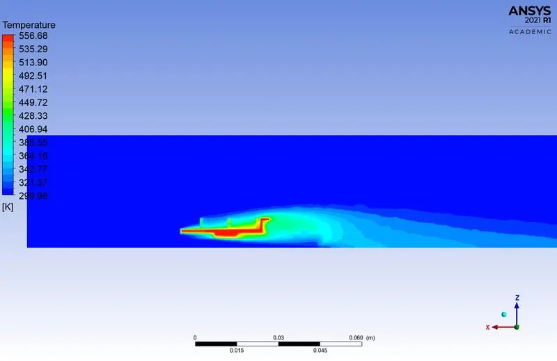
3. CFD Post-Processing Result.
Temperature contour:-
Velocity Contour:-
Surface Heat Transfer Coefficient:-
\*********__________**********__________*********__________*********__________*********__________*********__________*********__________*********/
Case 4 - Refined mesh with velocity 5 m/s.
1. Meshing:-
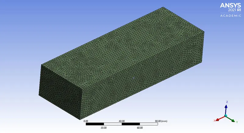
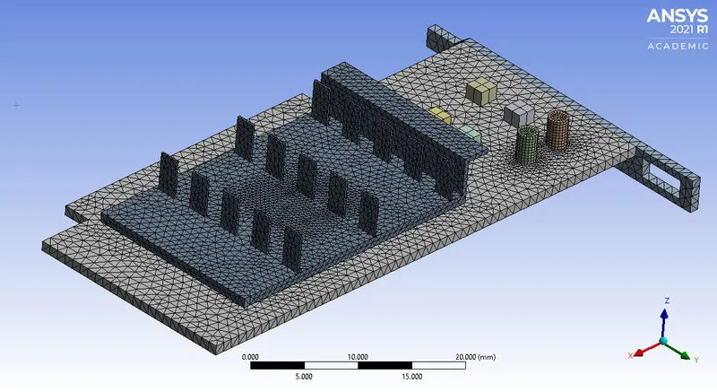
Fig(a). Enclosure Mesh Fig(b). Body Mesh of Fins
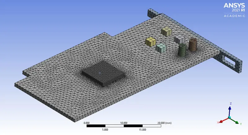
Fig(c). Body Mesh of Processor and Base.
Detail of Mesh:-
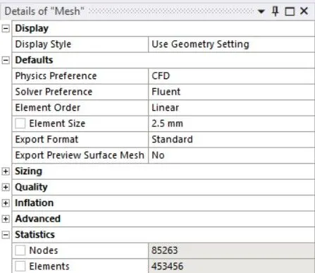
- Element size for Enclosure = 2.5 mm.
- Element size for Processor = 0.25 mm
- Element size for Fins = 0.75 mm.
- Element size for Base = 1 mm.
- Nodes = 85263
- No of Elements = 453456
2. Fluent Setup & Solving.
- Enable energy equation
- Viscous model = k - epsilon, standard.
Material:-
Fluid.
- Air
Solid.
- Aluminum
- Copper
- Steel
- Wood
Fig(1). Air Fig(2). Aluminum
Fig(3). Copper Fig(4). Steel
Fig(5). Wood
Cell Zones:-
- Enclosure - Air
- Base - Wood
- Fins - Copper
- Capacitors - Steel
- Port - Steel
- Processor - Aluminum with (source term = 312500000 `W//m^3`)
Fig(1). Air Fig(2). Wood
Fig(3). Copper Fig(4). Steel(capacitors)
Fig(5). Steel(port) Fig(6). Aluminum
Calculation of Power source:-
`"Source" = ("Power of the processor (W)")/("Volume of the processor (m^3)")`
`"Source" = 20/0.000000064`
`"Source" = "312500000 W/m^3"`
Note:- The processor power 20 watts is assumed.
Boundary condition:-
- Inlet Velocity = 5 m/s.
Residuals:-
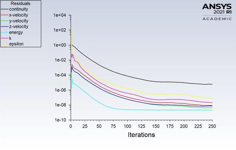
The solution is converged after the 75th iteration.
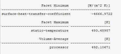
Facet Minimum:-
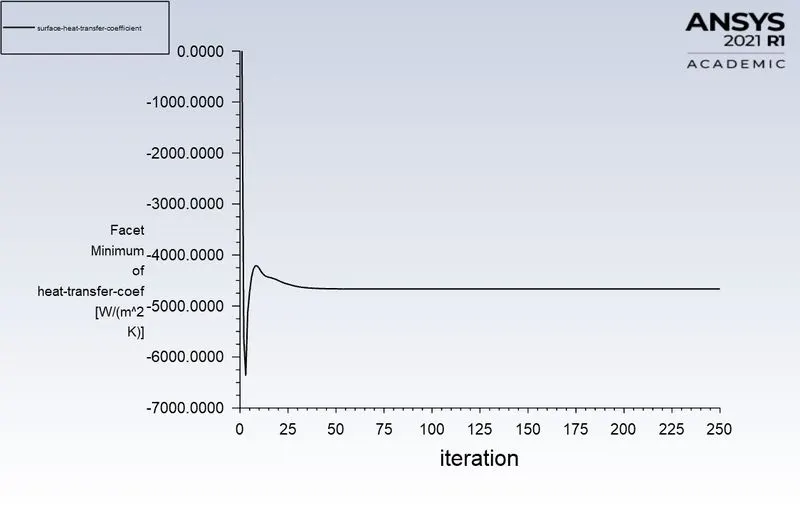
Surface Heat transfer coefficient = -4666.9722 [ `W//m^2.K`]
Facet Maximum:-
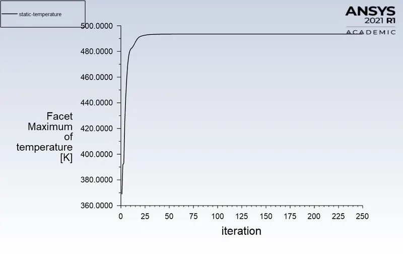
Static Temperature = 493.48987 K.
Volume Average:-
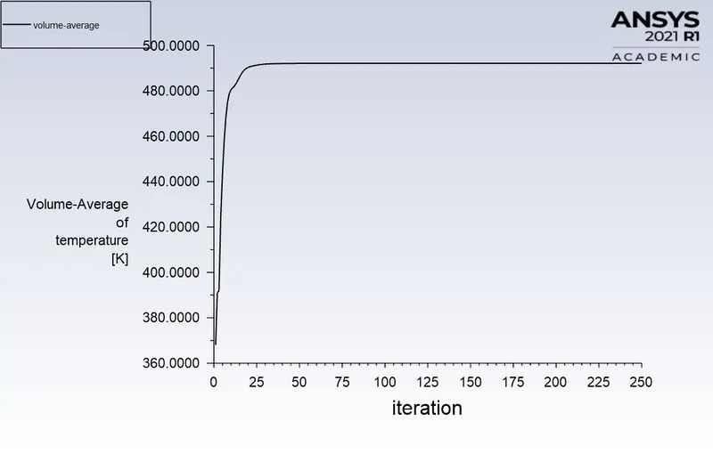
Average volume temperature in processor = 492.10671 K.
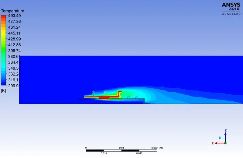
3. CFD Post-Processing Result.
Temperature contour:-
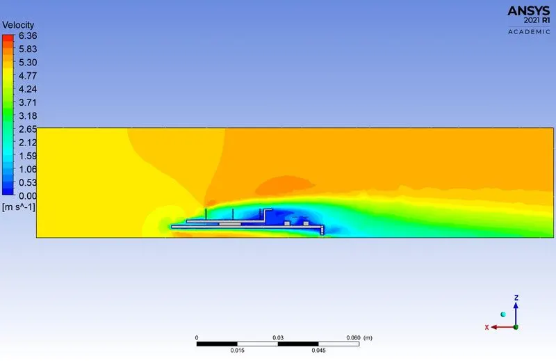
Velocity Contour:-
Surface Heat Transfer Coefficient:-
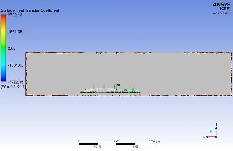
Comparision:-
| Velocity | Surface Heat Transfer Coef. | Temperature | |
| Case 1 (Baseline Mesh) | 1 m/s | -1344.0327 | 797.2558 |
| Case 2 (Refined Mesh) | 1 m/s | -1808.813 | 795.20605 |
| Case 3 (Refined Mesh) | 3 m/s | -3546.9055 | 556.68402 |
| Case 4 (Refined Mesh) | 5 m/s | -4666.9722 | 493.48987 |
Reason for choosing the particular mesh setting.
The body mesh is used in the processor, fins and base. Because thease are the main region to observe the heat transfer rate and temperature in the graphics card. The refine mesh help us to get the better result of temperature and heat transfer rate.
Conclusion:-
- From the ploted graph and comparision, the temperature of the processor is decrease if the velocity is increased.
- The surface heat transfer coefficient is also reduced due to the velocity increases.
- In the case 1 and 2 temperature should not be vary, but the SHTC is reduced. The refined mesh doesn't affect the temprature.
- The velocity is inversely proportional to the temperature and surface heat transfer coefficient.
- From all cases, the solution is converged between the 70 to 85 iteration.
- The hotspot of the graphics card is the Processor. It generates more heat because it is the main power source.
- The Fin is used only to transfer the heat from the processor.