Week 2 - Flow over a Cylinder.
FLOW OVER A CYLINDER
AIM:-
To simulate the flow over a cylinder with a steady and unsteady state of varying Reynolds number of 10, 100, 1000, 10000, 100000.
INTRODUCTION & THEORY:-
PART - 1
- Simulate the flow with steady and unsteady case and calculate the Strouhal number for Re = 100
PART - 2
- Calculate the coefficient of drag and lift over a cylinder by setting the Reynolds number to 10, 100, 1000, 10000, 100000. (Run with Steady solver).
- Discuss the effect of Reynolds number on the Co-efficient of drag.
Expected Result:
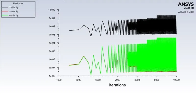
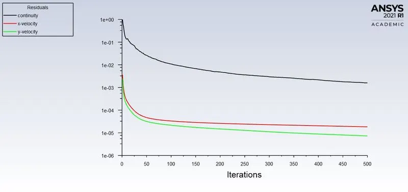
- In both approaches, show that the flow has converged. That is what quantities or plot need to be looked at to determine that the flow has converged.
- Plots of the Coefficient of drag and lift.
- Plot to show vortex shedding behind the cylinder.
- Mention the preferred material at the end of the challenge submission page.
Karman vortex street:-
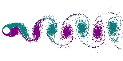
In fluid dynamics, a carmen vortex street is a repeating pattern of swirling vortices, caused by a process known as vortex shedding, which is responsible for the unsteady separation of flow of a fluid around blunt bodies. A vortex street will form only at a certain range of flow velocities, specified by a range of Reynolds number (Re), typically above a limiting Re value of about 90.
`Re = (rhoVD)/mu`
where,
ρ = density of the fluid (`kg//m^3`)
V = flow speed (m/s)
D = Diameter of the cylinder
`mu` = Dynamic viscosity of the fluid (`kg//m.s`)
Strouhal number:
`St = (fd)/U`
`f = ("Number of cycles")/(Time)`
where,
- f = vortex shedding frequency.
- d = diameter of the cylinder.
- U = Flow Velocity
Coefficient of Drag:
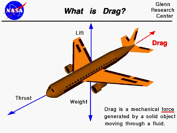
In fluid dynamics, the drag coefficient is a dimensionless quantify the drag or resistance of an object in a fluid environment, such as air or water. It is used in the drag equation in which a lower drag coefficient indicates the object will have less aerodynamic or hydrodynamic drag. The drag coefficient is always associated with a particular surface area.
Coefficient of Lift:
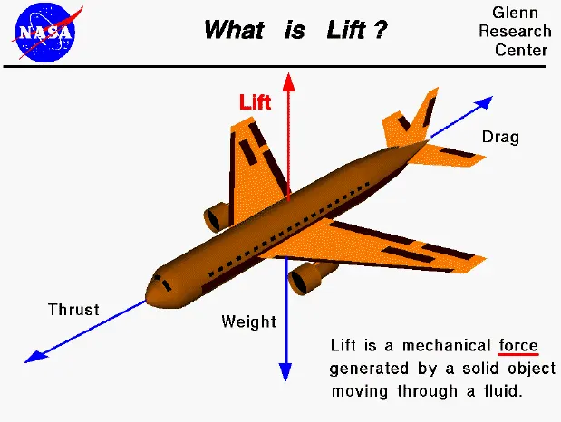
The lift coefficient is a dimensionless coefficient that relates to the lift generated by a lifting body to the fluid density around the body, the fluid velocity, and an associated reference area. A lifting body is a foil or a complete foil-bearing body such as a fixed-wing aircraft. The lift coefficient is a function of the angle of the body to the flow, its Reynolds number, and Mach number. The section lift coefficient refers to the dynamic lift characteristics of a two-dimensional foil section, with the reference area replaced by the foil chord.
SIMULATION PROCESS:
Geometry Model:-
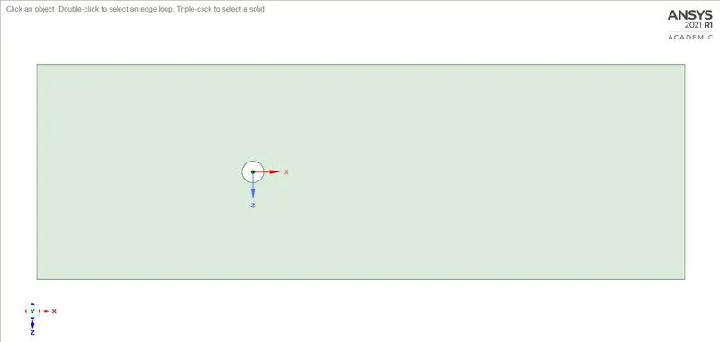
The 2D model is created by ANSYS SpaceClaim software.
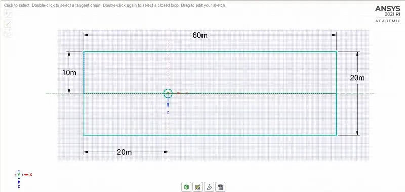
The Above geometry is to be pulled and cut the circle for the desired geometry.
Meshing:-
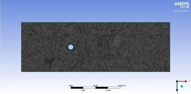
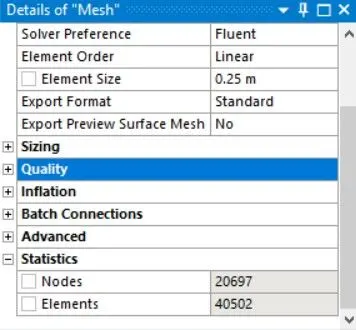
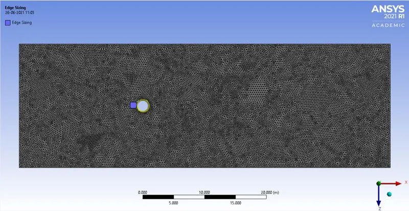
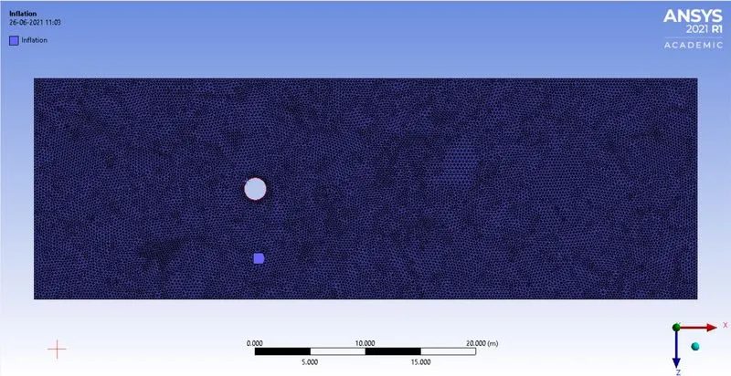
The model is meshed using an ANSYS mesher with an element size of 0.25m and the triangular method is used.
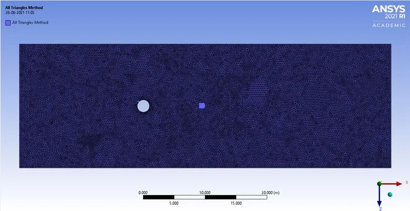
All triangular methods:-
Edge sizing:-
Inflation:-
Model:-
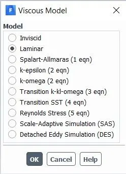
A laminar viscous model is selected.
Material:-
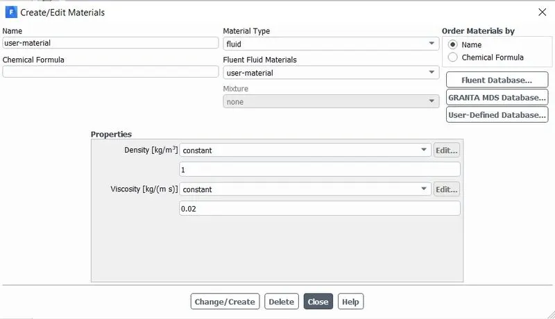
The user material is created for changing the required value of the fluid.
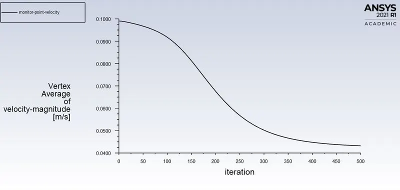
Monitor Point:-
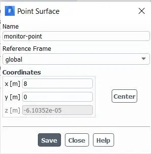
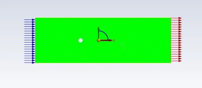
The monitor point is created at a distance of 8m from the inlet. The point is used to monitor the velocity of the fluid flow.
\***************************************************************************************************************************************/
PART - 1:-
- Case - 1:- Steady-state solver of Re = 100
- Case - 2:- Transient state solver of Re = 100
Case - 1:- Steady-state solver of Re = 100
Setup Fluent:-
Boundary conditions:-
- Density = 1 [`kg//m^3`]
- Velocity = 1[`m//s`]
- Viscosity = 0.02 [`kg//(m.s)`]
Run Calculation:-
No. of Iteration = 500
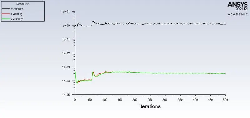
Residuals:-
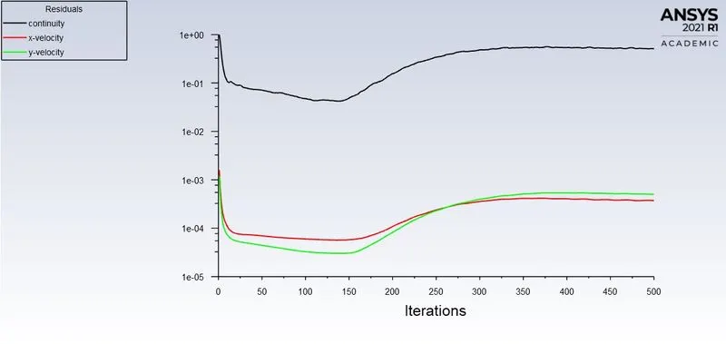
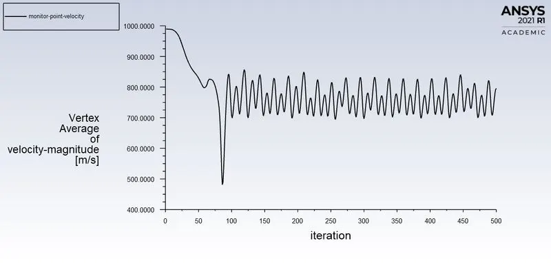
Vertex Average (Monitor point velocity):-
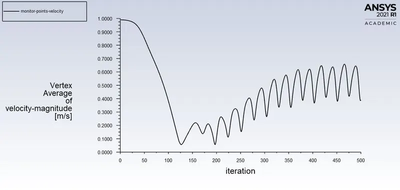

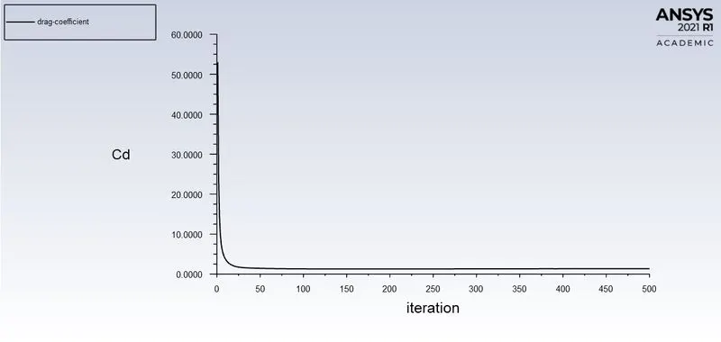
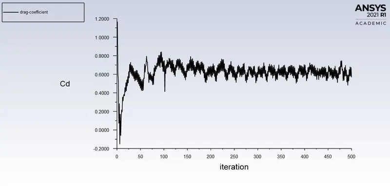
Drag-Coefficient:-

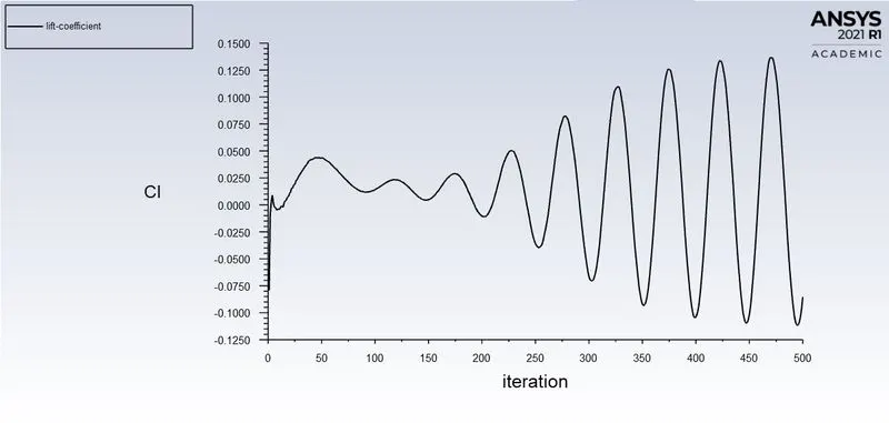
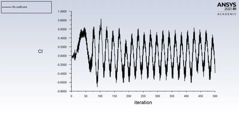
Lift - Coefficient:-

Post - Processing Result:-
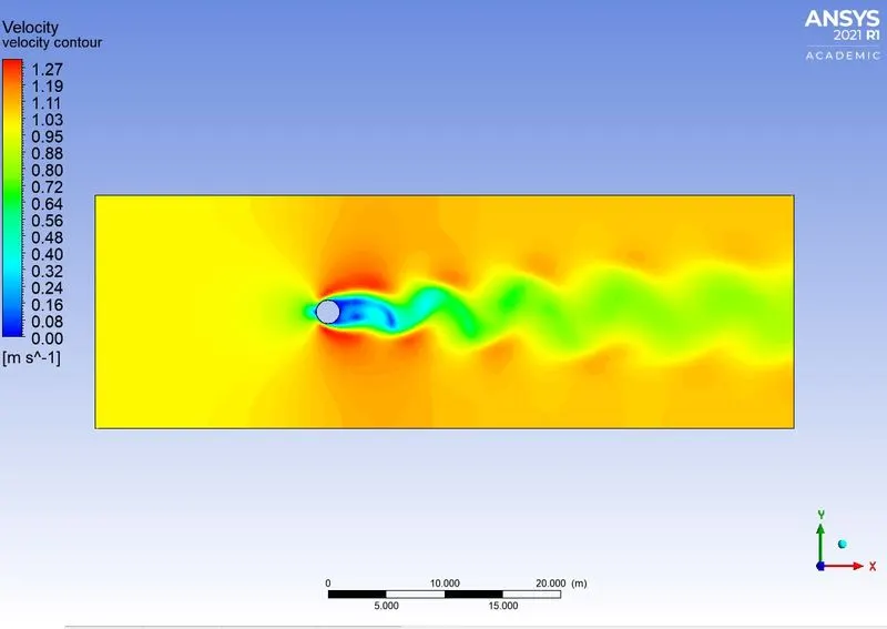
Velocity Contour:-
Pressure Contour:-
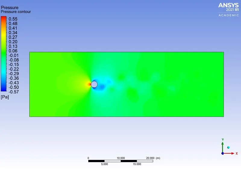
From the above plots, the vortex shedding should be created after the 130 iterations.
Case - 2:- Transient state solver of Re = 100
Setup Fluent:-
Boundary Conditions:-
- Density = 1 [`kg//m^3`]
- Velocity = 1[`m//s`]
- Viscosity = 0.02 [`kg//(m.s)`
Run Calculation:-
- Time Step Size [s] = 0.2
- No. of Time Steps = 500
Residuals:-
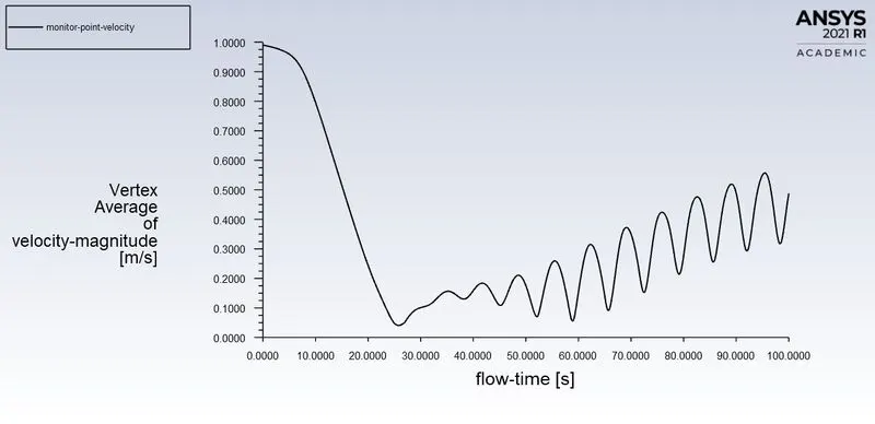
Vertex Average (Monitor Point Velocity):-

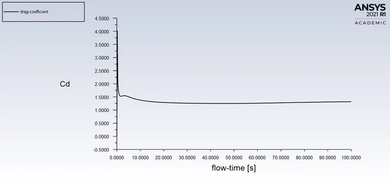
Drag - Coefficient:-

Lift - Coefficient:-
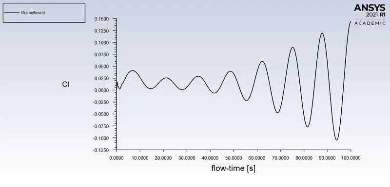

Strouhal number:
`St = (fd)/U`
`f = ("Number of cycles")/(Time)`
d = 2m (Diameter of the cylinder)
U = 1m/s (Flow Velocity)
f = 3/(80-40)
f = 0.075
St = (0.075*2) / (1)
St = 0.15
The Strouhal number is calculated from the coefficient of the lift plot.
Post - Processing Result:-
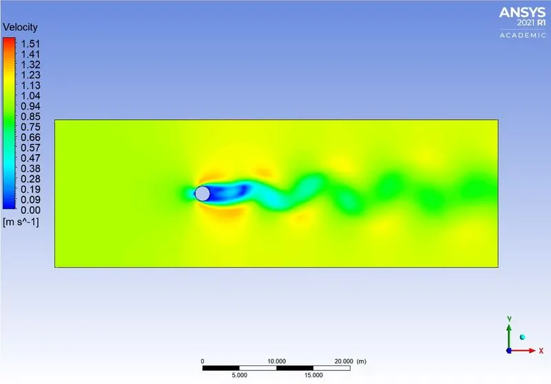
Velocity Contour:-
Pressure Contour:-
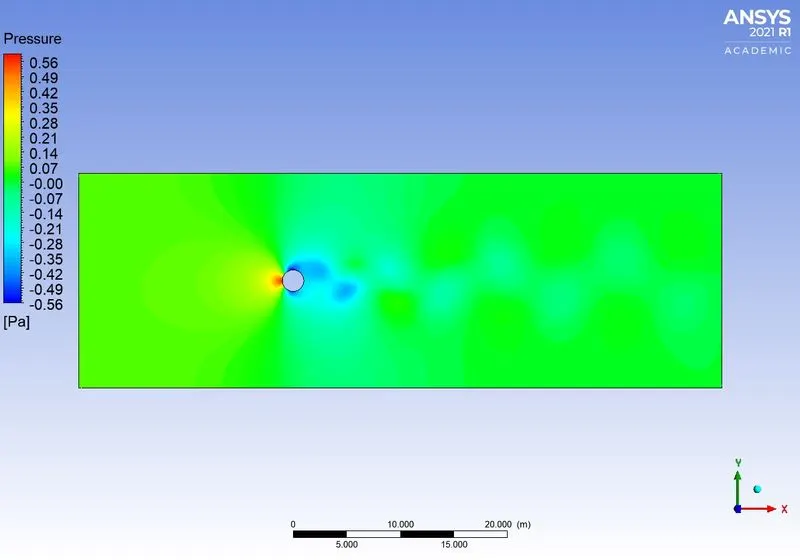
From the above plots, the vortex shedding should be created after the Flow-time 26s.
Velocity Animation:-
\***************************************************************************************************************************************/
PART - 2:-
In this part, the simulation of the steady-state solver is taken up to solve the Reynolds number of 10, 100, 1000, 10000, 100000.
- Case - 1:- Re = 10
- Case - 2:- Re = 100
- Case - 3:- Re = 1000
- Case - 4:- Re = 10000
- Case - 5:- Re = 100000
Case - 1:- Re = 10
Setup Fluent:-
Boundary Conditions:-
- Density = 1 [`kg//m^3`]
- Velocity = 0.1 [`m//s`]
- Viscosity = 0.02 [`kg//(m.s)`
Run Calculation:-
- No. of Iteration = 500
Residuals:-
Vertex Average (Monitor Point Velocity):-

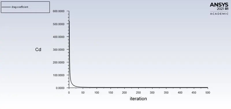
Drag - Coefficient:-

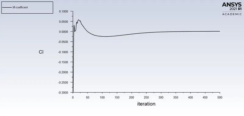
Lift - Coefficient:-

Post - Processing Result:-
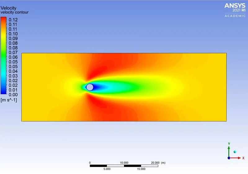
Velocity Contour:-
Pressure Contour:-
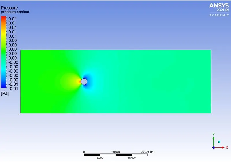
From the above plots, the vortex shedding shouldn't create. Because the vortex should be created if the Reynolds number (Re) > 90.
Case - 2:- Re = 100
Setup Fluent:-
Boundary Conditions:-
- Density = 1 [`kg//m^3`]
- Velocity = 1 [`m//s`]
- Viscosity = 0.02 [`kg//(m.s)`
Run Calculation:-
- No. of Iteration = 500
Residuals:-
Vertex Average (Monitor Point Velocity):-
Drag - Coefficient:-
Lift - Coefficient:-
Post - Processing Result:-
Velocity Contour:-
Pressure Contour:-
From the above plots, the vortex shedding should be created after the 130 iterations.
Case - 3:- Re = 1000
Setup Fluent:-
Boundary Conditions:-
- Density = 1 [`kg//m^3`]
- Velocity = 10 [`m//s`]
- Viscosity = 0.02 [`kg//(m.s)`
Run Calculation:-
- No. of Iteration = 500
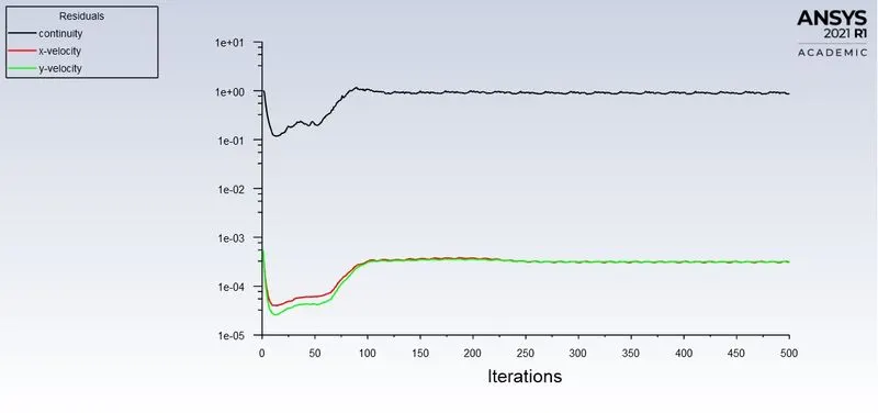
Residuals:-
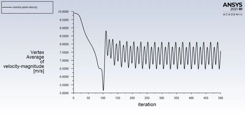
Vertex Average (Monitor Point Velocity):-

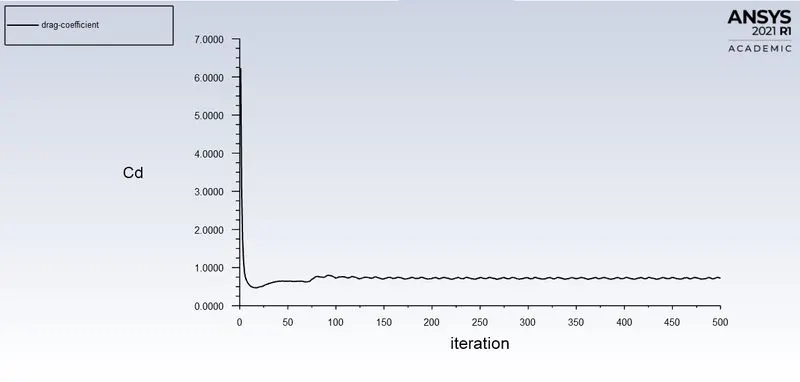
Drag - Coefficient:-

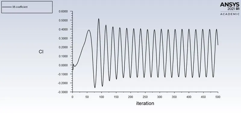
Lift - Coefficient:-

Post - Processing Result:-
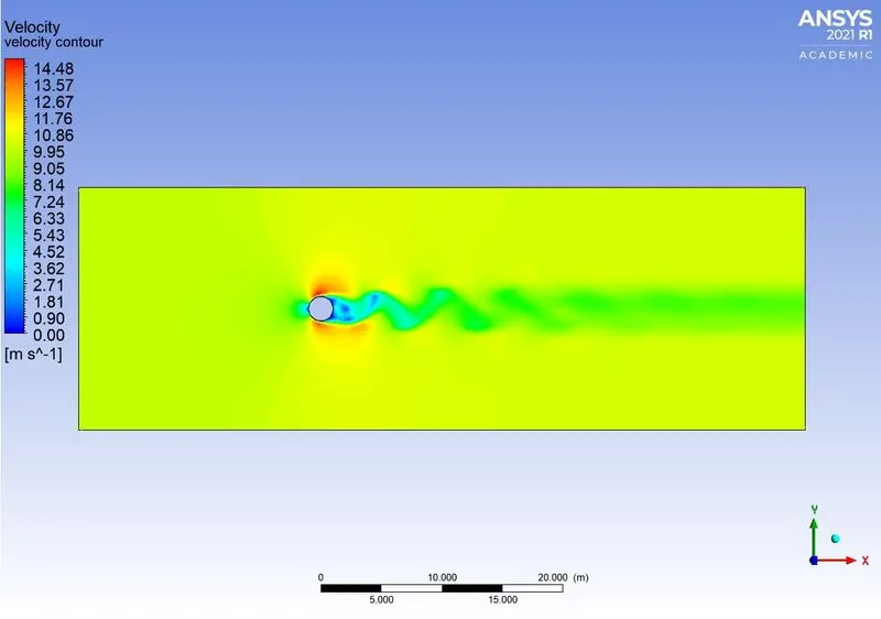
Velocity Contour:-
Pressure Contour:-
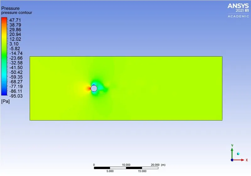
From the above plots, the vortex shedding should be created after the 100 iterations.
Case - 4:- Re = 10000
Setup Fluent:-
Boundary Conditions:-
- Density = 1 [`kg//m^3`]
- Velocity = 100 [`m//s`]
- Viscosity = 0.02 [`kg//(m.s)`
Run Calculation:-
- No. of Iteration = 500
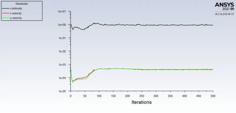
Residuals:-
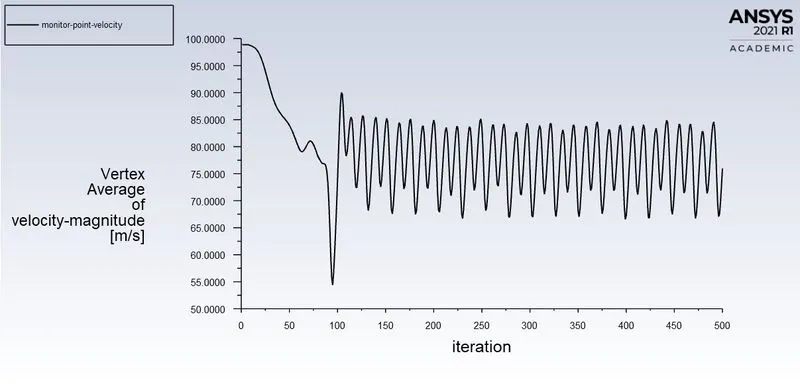
Vertex Average (Monitor Point Velocity):-

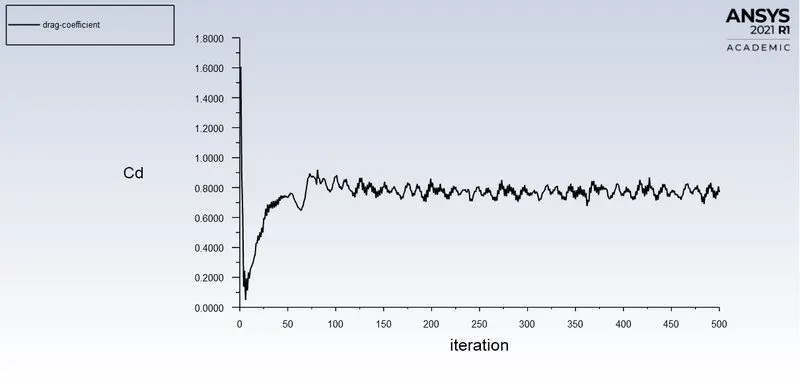
Drag - Coefficient:-

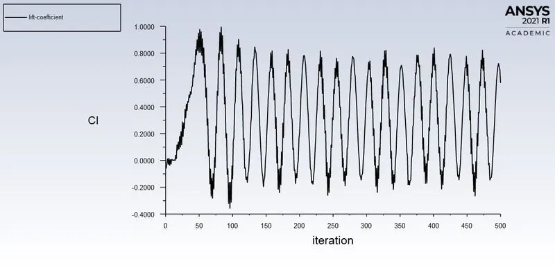
Lift - Coefficient:-

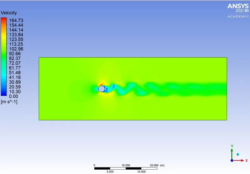
Post - Processing Result:-
Velocity Contour:-
Pressure Contour:-
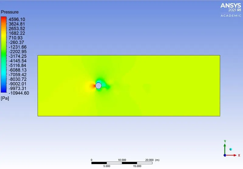
From the above plots, the vortex shedding should be created after the 90 iterations.
Case - 5:- Re = 100000
Setup Fluent:-
Boundary Conditions:-
- Density = 1 [`kg//m^3`]
- Velocity = 1000 [`m//s`]
- Viscosity = 0.02 [`kg//(m.s)`
Run Calculation:-
- No. of Iteration = 500
Residuals:-
Vertex Average (Monitor Point Velocity):-

Drag - Coefficient:-

Lift - Coefficient:-

Post - Processing Result:-
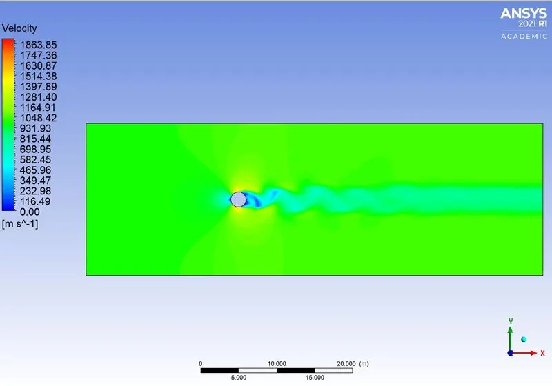
Velocity Contour:-
Pressure Contour:-
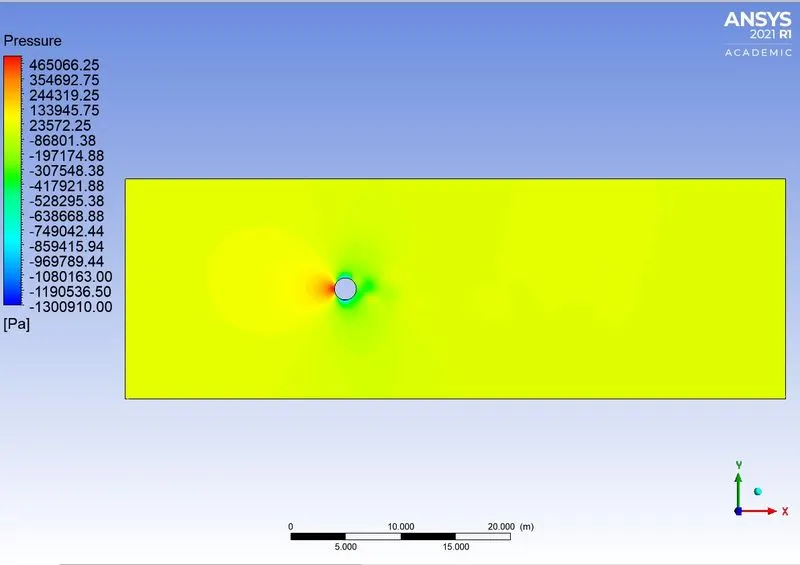
From the above plots, the vortex shedding should be created after the 85 iterations.
Conclusion:-
Tabulation:-
Reynolds Number Coefficient of Drag(CD) Coefficient of Lift(CL) Iteration to converge
10 (steady) 3.3300532 0.00092048865 -
100 (steady) 1.3340513 -0.085381276 130
1000 (steady) 0.72467203 0.22066491 100
10000 (steady) 0.76936507 0.57776197 90
100000 (steady) 0.5673428 -0.3910866 85
100 (Unsteady) 1.3203995 0.14402629 26 sec
From the above plots and table, the Karman vortex shedding is created above the Re > 90. And an increase in velocity, the flow is converged faster.
Effects of Reynolds number on the coefficient of drag:-
If the Reynolds number increases the coefficient of drag is decreased. That is the velocity is inversely proportional to the Drag coefficient. If the velocity increases the Reynolds number also increased.
Referred Material:-
Composite materials are also used within the aircraft industry due to the strength, relatively low weight and corrosion resistance. composites are created by the combination of different materials, which have been selected on the basis of their structural properties.
They can be made of fibrous material embedded within a resin matrix. The fibrous oriented in a specific direction are laminated with fibres characterised by a different orientation in order to obtain the required strength and stiffness.