Battery Technology Project: Fuel cell powered model
Aim:
To simulate the 6 kW 45 Vdc Fuel Cell Stack built-in model in Matlab Simulink.
Theory:
A fuel cell is a device that uses a chemical reaction to generate electricity. Every fuel cell has two electrodes known as the anode and cathode. The electrodes are where the reactions that generate electricity take place. Every fuel cell also contains an electrolyte, which transports electrically charged particles from one electrode to the next, as well as a catalyst, which accelerates the reactions at the electrodes. Although hydrogen is the most basic fuel, fuel cells also require oxygen. One of the most appealing aspects of fuel cells is that they produce very little pollution—much of the hydrogen and oxygen used to generate electricity eventually combine to form a harmless byproduct, namely water.
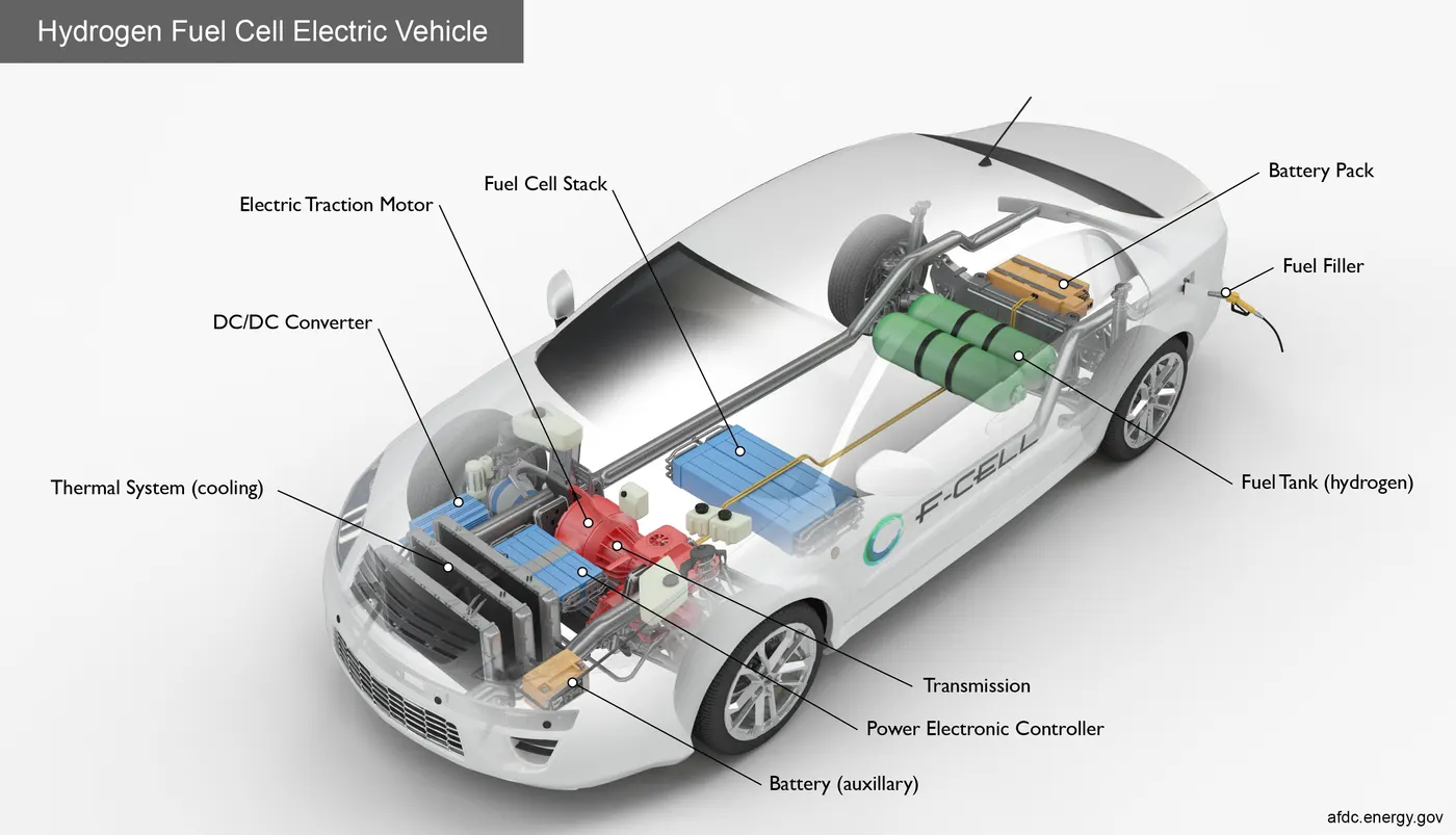
Figure: Hydrogen Fuel Cell Vehicle [link]
A technical note: a single fuel cell produces a negligible amount of direct current (DC) electricity. In practise, many fuel cells are usually stacked together. The principles are the same whether in a cell or a stack.
Fuel cells have numerous applications, including transportation, material handling, stationary, portable, and emergency backup power. Fuel cells have a number of advantages over traditional combustion-based technologies that are currently used in many power plants and passenger vehicles. Fuel cells can operate at higher efficiencies than combustion engines, converting chemical energy in fuel to electrical energy with up to 60% efficiency. Fuel cells emit fewer pollutants than combustion engines. Because hydrogen fuel cells emit only water, there are no carbon dioxide emissions or air pollutants at the point of operation, which causes smog and health problems. Furthermore, because they have fewer moving parts, fuel cells operate quietly.
Basic Elements of a Polymer Electrolyte Membrane Fuel Cell:
The anode, or negative post of the fuel cell, serves several functions. It conducts electrons liberated from hydrogen molecules so that they can be used in an external circuit. It has channels etched into it that evenly distribute the hydrogen gas across the surface of the catalyst. The cathode, or positive post of the fuel cell, has etched channels that distribute oxygen to the catalyst's surface. It also returns electrons from the external circuit to the catalyst, where they recombine with hydrogen ions and oxygen to form water.
The proton exchange membrane is the electrolyte. This specially treated material, which resembles ordinary kitchen plastic wrap, conducts only positively charged ions. Electrons are blocked by the membrane. In order for a PEMFC to function and remain stable, the membrane must be hydrated.
The catalyst is a special substance that aids in the reaction of oxygen and hydrogen. It is typically composed of platinum nanoparticles that have been very thinly coated onto carbon paper or cloth. The catalyst is rough and porous so that as much platinum surface area as possible is exposed to the hydrogen or oxygen. The platinum-coated side of the catalyst is in contact with the PEM.
Main Components of a Fuel Cell:
An automotive fuel cell system can run on a variety of fuels, with the choice influenced by factors such as fuel supply infrastructure, fuel cost, storage complexity and cost, safety, environmental implications, and national energy policy. Proper hydrogen storage is essential for the mass commercialization of fuel cell vehicles. Hydrogen can be stored in a variety of forms, including compressed gas, liquid, and metal hyrides. Compressed gas storage tanks are large and bulky. New cars have an average fuel efficiency of 20 to 30 mpg; European and Japanese cars have even lower averages. Current vehicles have a capacity of 10 to 16 gallons of gasoline, or 30 to 45 litres. Because hydrogen vehicles are twice as efficient as gasoline vehicles, they can theoretically store 5 to 8 kg of hydrogen, which is equivalent to 200 to 400 L—a significant reduction in fuel storage space. Although liquid hydrogen tanks are less bulky, they must be kept at extremely low temperatures.
Working Principle of Fuel Cells:
A fuel cell's purpose is to generate an electrical current that can be directed outside the cell to do work, such as powering an electric motor or lighting a city. Due to the nature of electricity, this current returns to the fuel cell, completing an electrical circuit. The chemical reactions that generate this current are critical to the operation of a fuel cell.
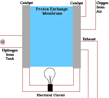
Figure: Working of Fuel Cell [Schatz Energy Research Center, link]
There are various types of fuel cells, each of which operates slightly differently. In general, hydrogen atoms enter a fuel cell at the anode, where they are stripped of their electrons by a chemical reaction. The hydrogen atoms have been "ionised," and they now have a positive electrical charge. Negatively charged electrons conduct current through wires to perform work. If alternating current (AC) is required, the fuel cell's direct current (DC) output must be routed through a conversion device known as an inverter.
Oxygen enters the fuel cell at the cathode, where it combines with electrons returning from the electrical circuit and hydrogen ions that have travelled through the electrolyte from the anode in some cell types (such as the one shown above). In other types of cells, oxygen picks up electrons before travelling through the electrolyte to the anode, where it combines with hydrogen ions.
The electrolyte is crucial. It must allow only the necessary ions to pass between the anode and cathode. If free electrons or other substances could pass through the electrolyte, the chemical reaction would be disrupted. Whether they combine at the anode or cathode, hydrogen and oxygen combine to form water, which drains from the cell. A fuel cell will generate electricity as long as it is supplied with hydrogen and oxygen. Even better, because fuel cells generate electricity chemically rather than through combustion, they are not constrained by the thermodynamic laws that constrain conventional power plants. As a result, fuel cells extract more energy from a fuel more efficiently. Waste heat from some cells can also be utilised, increasing system efficiency even further.
Types of Fuel Cells:
- Alkali Fuel Cells:
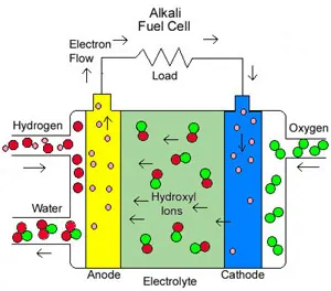
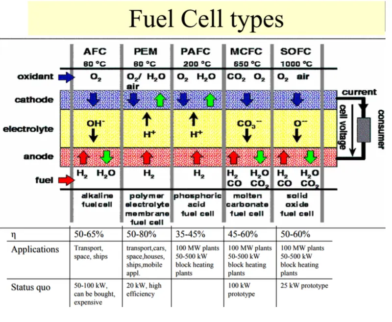
Alkali fuel cells use compressed hydrogen and oxygen to power themselves. As an electrolyte, they typically use a solution of potassium hydroxide (chemically, KOH) in water. The efficiency is around 70%, and the operating temperature ranges from 150 to 200 degrees Celsius (about 300 to 400 degrees F). The output of the cell ranges from 300 watts (W) to 5 kilowatts (KW) (kW). In Apollo spacecraft, alkali cells were used to provide both electricity and drinking water. However, they require pure hydrogen fuel, and their platinum electrode catalysts are costly. And, like any other container containing liquid, they can leak. - Molten Carbonate Fuel Cells (MCFC):
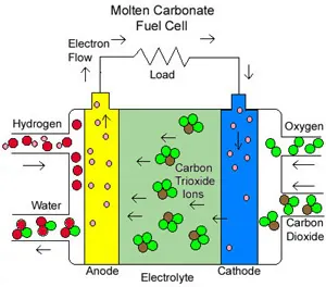
The electrolyte in molten carbonate fuel cells (MCFC) is a high-temperature compound of salt (like sodium or magnesium) carbonates (chemically, CO3). The efficiency ranges between 60 and 80 percent, and the operating temperature is around 650 degrees Celsius (1,200 degrees F). Units with outputs of up to 2 megawatts (MW) have been built, and designs for units with outputs of up to 100 MW exist. The high temperature prevents cell damage from carbon monoxide "poisoning," and waste heat can be recycled to generate additional electricity. When compared to the platinum used in other cells, their nickel electrode-catalysts are less expensive. However, the high temperature limits the materials and safe applications of MCFCs—they are probably too hot for home use. - Phosphoric Acid Fuel Cells (PAFC):
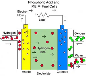
The electrolyte in phosphoric acid fuel cells (PAFC) is phosphoric acid. The efficiency ranges from 40 to 80 percent, and the operating temperature ranges from 150 to 200 degrees Celsius (about 300 to 400 degrees F). There are currently phosphoric acid cells with outputs of up to 200 kW, and 11 MW units have been tested. PAFCs can withstand a carbon monoxide concentration of about 1.5 percent, allowing them to use a wider range of fuels. When using gasoline, the sulphur must be removed. Platinum electrode-catalysts are required, as are internal parts that can withstand the corrosive acid. - Proton Exchange Membrane Fuel Cell (PEM):
Proton Exchange Membrane (PEM) fuel cells use a polymer electrolyte in the form of a thin, permeable sheet as an electrolyte. The efficiency ranges between 40 and 50 percent, and the operating temperature is around 80 degrees Celsius (about 175 degrees F). Cell outputs typically range between 50 and 250 kW. The solid, flexible electrolyte will not leak or crack, and these cells operate at temperatures low enough to be used in homes and cars. Their fuels, however, must be purified, and a platinum catalyst is used on both sides of the membrane, increasing costs. - Solid Oxide Fuel Cells (SOFC):
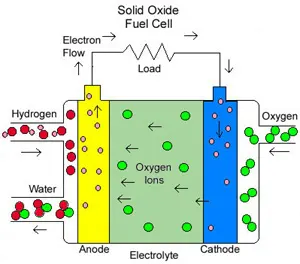
As the electrolyte in solid oxide fuel cells (SOFC), a hard, ceramic compound of metal oxides (such as calcium or zirconium) (chemically, O2) is used. The efficiency is around 60%, and the operating temperatures are around 1,000 degrees Celsius (about 1,800 degrees F). The output of the cells can reach 100 kW. A reformer is not required to extract hydrogen from the fuel at such high temperatures, and waste heat can be recycled to generate additional electricity. However, the high temperature limits the applications of SOFC units, and they are typically quite large. Solid electrolytes, while not leaking, can crack.
RL Circuit:
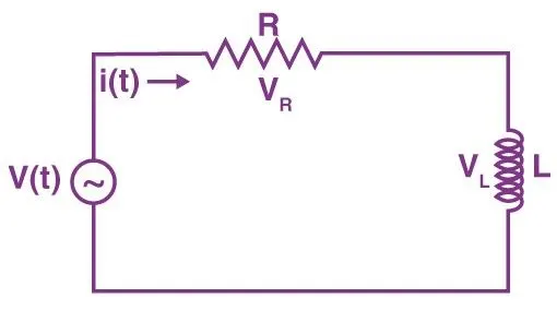
RL Circuits (resistor-inductor circuit), also known as RL networks or RL filters, are a type of circuit that is powered by a combination of inductors and resistors. As a result, in an RL circuit, an inductor and a resistor are connected in either parallel or series. They can be powered by a current (parallel) or a voltage (series) source. Furthermore, the basic passive linear circuit elements are the resistor (R), inductor (L), and capacitor (C). They can create an electrical circuit in four ways, including the RC circuit, the LC circuit, and the RLC circuit.
Objectives:
- To understand the theory and working of Fuel Cells.
- To explore 6 kW 45 Vdc Fuel Cell Stack built-in model in Matlab.
- To understand the working priniciple of the model.
- To simulate the model and understand various characteristics.
Simulink Model of a Fuel Cell Powered Electric Vehicle:
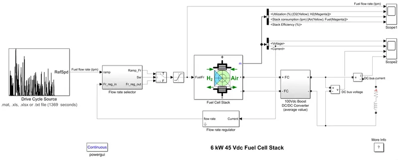
The nominal voltage of the Fuel Cell Stack is 45Vdc, and the nominal power is 6kW. The converter is powered by a 6kW RL element with a time constant of 1 second. Using a fuel flow rate regulator, the utilisation of hydrogen is constant to the nominal value (Uf H2 = 99.56%) during the first 10 seconds. After 10 seconds, the flow rate regulator is bypassed, and the fuel rate is increased to the maximum value of 85 lpm to observe the variation in stack voltage. This will have an impact on stack efficiency, fuel consumption, and air consumption.
The Scope2 can display fuel cell voltage, current, DC/DC converter voltage, and DC/DC converter current signals. The Scope1 displays fuel flow rate, hydrogen and oxygen utilisation, fuel and air consumption, and efficiency.
The flow rate selector provides the initial input, which is then routed to the fuel cell stack, which is combined with the boost converter, and the RL circuit provides the output to the boost converter. Because the load produced by the RL circuit needed to be the same as the electricity produced by the FUEL CELL STACK, this arrangement was made by the BOOST CONVERTER. If this is not equal, the electricity produced by will not be able to move the load any further.
Blocks used:
- Fuel Cell Stack: A Proton Exchange Membrane Fuel Cell (PEMFC) stack capable of producing 6kW of power and 45Vdc has been selected. Because the RL load requires a voltage of 100Vdc, a boost converter is required. Here, input the fuell cell stack can be increased as only the fuel flow rate is provided initially but can also provide what will be the air flow rate for the oxygen supply, air pressure, fuel composition, etc.
The VI characteristics of the fuel cell is as below: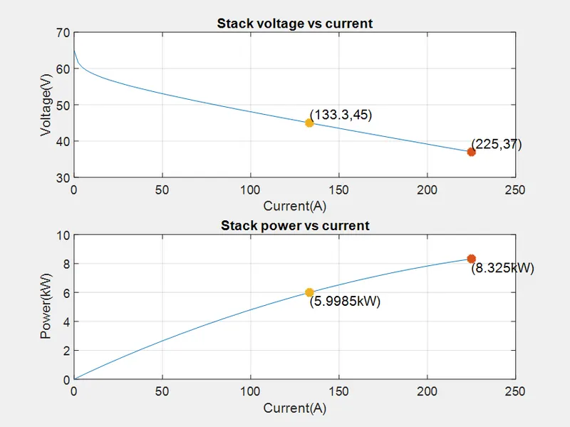
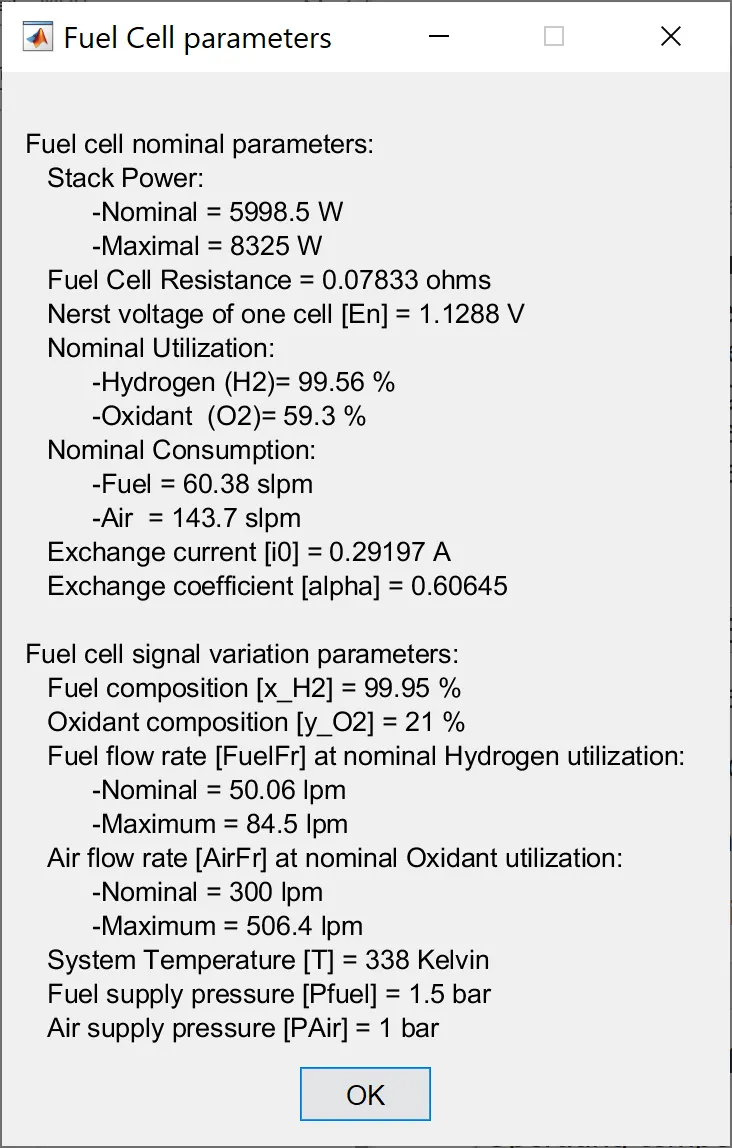
The nominal stack power is approximately 6kW with 45Vdc and 133A, as shown by the graph and the FC parameters. Because that 6kW must be maintained, voltage and current have an inversely proportional relationship, which means that as current increases, voltage must decrease to maintain the same power output. As stack current increases, so does the rate of electrical energy generation, resulting in more power from the fuel cell. - Flow Rate Selector: The input is first given through the flow rate selector, which provides the rate of flow per litre with the regulation. If the regulation is increased, the flow rate is supplied, which then goes to the switch.
- Switch: it is used to change the fuel flow rate according according to the condition.
- Saturation: it is used to make sure the the maximum limit of passing the flow rate will be 85 and the minimul limit will be 0.
- Boost Converter: A boost converter (step-up converter) is a DC-to-DC power converter that increases voltage while decreasing current from the input (supply) to the output (load). The fuel cell stack is linked to this boost converter. An RL circuit is added to the boost converter's other end.
The equivalent circuit for the block with duty cycle as input is shown in the diagram. A controlled current source and a controlled voltage source are included in the converter. To convert the electrical energy between the connected components on either side of the converter, use the duty cycle, current reference, or voltage reference ports as control input.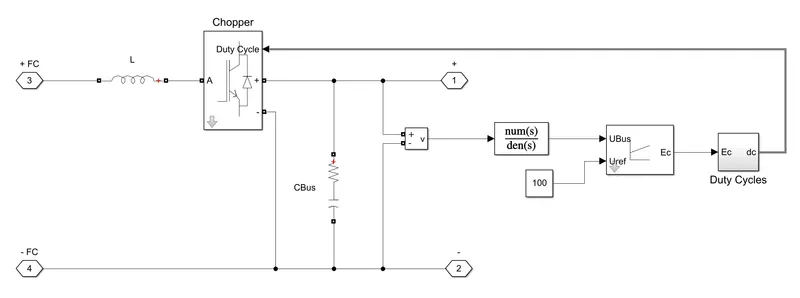
- Working of Boost DC/DC Converters:
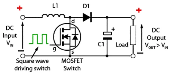
The roles of the inductor and capacitor are critical for understanding the entire circuit: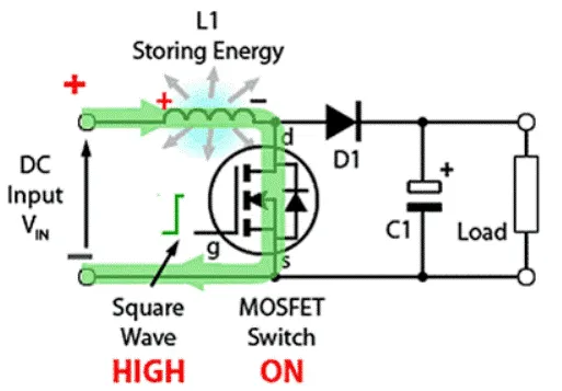
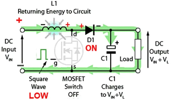
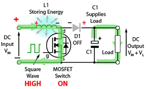
According to figure , current flows through the inductor when the FET switch is turned on during the positive half cycle of the DC wave. An inductor is a wire coil that conducts current, creating a magnetic field that stores energy `V_L`. Because no new current is flowing through the inductor during the negative half cycle, there is nothing to hold the induced magnetic field in place. The induced magnetic field begins to weaken, releasing the stored energy `V_L`. (change in field flux in a coil of wire induces current flow). Now, current flows to the capacitor (an energy storage element) and the load, charging the capacitor with V IN + `V_L`. `V_(IN)`+ `V_L` is the output voltage across the parallelly connected load. The capacitor releases its energy to increase the potential difference across the load once the second period begins and the FET switch is turned back on. Because of the diode, the capacitor cannot discharge its energy to the inductor, so it all flows to the load. This process is repeated as the FET switch is turned on and off multiple times in a single second, and this is how V IN is boosted to `V_(IN)`+ `V_L` for each cycle, until the voltage limit for the load is reached.
- Working of Boost DC/DC Converters:
- RL Circuit: A single resistor, inductor, or capacitor, or a series combination of these, is implemented by the Series RLC Branch block. Select the elements you want to include in the branch using the Branch type parameter. Resistance, inductance, and capacitance can all have negative values.
- Flow Rate Regulator: The flow rate regulator will operate on the basis of the current produced by the fuel cell stack.
- Powergui: The powergui block allows one to choose one of these methods to solve your circuit: Continuous, which uses a variable-step solver from Simulink; Discretization of the electrical system for a solution at fixed time steps; and Continuous or discrete phasor solution.
Output of the Simulink Model:
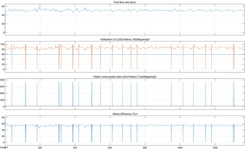
- Fuel flow rate: this remains constant at around 50 lpm until 20 seconds because, as seen in the UDDS drive cycle, the car is at rest until then as well. When the fuel cell is at rest, it must receive a standby flow rate of 50 lpm in order to possibly prepare the vehicle for propulsion after its resting period. This can also be seen from 125 sec to 165 sec, where the flow rate is a constant 50 lpm as the vehicle is at rest. The flow rate increases whenever the vehicle needs to accelerate. Similarly, as the vehicle slows, the flow rate decreases.
- Fuel Utilization: The most noticeable observation is that oxygen has minimal fluctuations and is always around 60%. This could be because the fuel cell requires a constant supply of oxygen in order for the byproduct to form harmlessly. If there is insufficient oxygen, incomplete combustion may occur, resulting in the release of pollutants. More hydrogen is used every time the vehicle accelerates. Hydrogen utilisation changes dramatically just before 40 seconds, twice before 120 seconds, and once at 185 seconds. This is because there is a sharp deceleration and hard braking, which is reflected in the drive cycle (current is flowing in the negative direction). As a result, during severe deceleration, there is no need for any fuel, which is why hydrogen falls to 0%. It is not visible in the graphs until you zoom in, but at these points, oxygen utilisation also falls to zero, which makes sense because oxygen has no use without the presence of hydrogen.
- Stack Consumption: This displays the amount of fuel and oxygen consumed by the stack. The fuel flow rate and utilisation of fuel are fairly stable throughout the cycle, demonstrating the stable nature of hydrogen consumption. Oxygen, on the other hand, exhibits dramatic changes at various points, as seen in the other graphs. When there is a rapid deceleration, oxygen is consumed from the stack but not used because there is no hydrogen available to combust to produce water.
- Stack Efficieny: This graph is similar to the fuel utilisation graph in that efficiency drops to 0% when there is a rapid deceleration, which is because fuel isn't being used and thus efficiency cannot be determined. Aside from that, efficiency is slightly less than 60%.
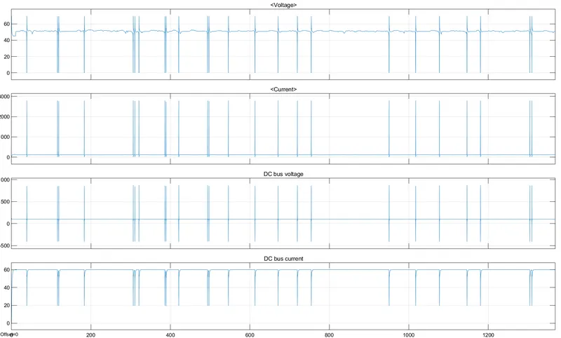
- Voltage: The movement of the vehicle explains the voltage fluctuation. All of those voltage spikes are caused by abrupt acceleration and deceleration. When there is a sudden acceleration, the voltage rises to approximately 70V, and when there is a sudden deceleration, the voltage falls to zero.
- Current: The voltage graph is exactly the opposite of the current graph, in that when voltage increases dramatically, current decreases dramatically, and vice versa. This must be the case because this fuel cell is expected to produce a constant power output of 6kW (P = VI).
- DC Bus Voltage: this showcases the output voltage after the boost converter has been in operation, which is why the voltage is at a constant 100Vdc with a few fluctuations that are identical to the voltage graph due to the sudden changes in speed of the vehicle
- DC Bus Current: This displays the output current after the boost converter has been activated. The boost converter is in charge of increasing the voltage, which means that the output current will be reduced by the same factor to maintain a constant power output. As seen in the current graph, it is constantly around 130A with occasional fluctuations, and after passing through the boost converter, it has dropped to 60A.
Conclusion:
For the 6 kW 45 Vdc Fuel Cell Stack built-in model in Matlab, the working priniciple of the model has been explained after simulating the model. Also, the voltage and current characteristics in the resultant graphs are also been discussed.